Category AIRCRAF DESIGN

Civil Aircraft Design: Future Trends

The speed-altitude extension will progress initially through supersonic transport (SST) and then hypersonic transport (HST) vehicles. The SST technology is well proven by three decades of the Anglo-French-designed Concorde, which operated above Mach 2 at a 50,000-ft altitude carrying 128 passengers.

Civil Aircraft Design: Future Trends
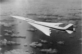
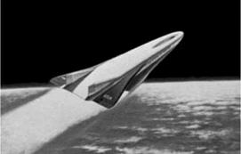
The next-generation SST will have about the same speed-altitude capabil­ity (possibly less in speed capability, around Mach 1.8), but the size will vary from as few as 10 business passengers to approximately 300 passengers to cover at least transatlantic and transcontinental operations. Transcontinental operations (Figure 1.12) would demand sonic-shock-strength reduction through aerodynamic gains rather than speed reduction; anything less than Mach 1.6 has less to offer in terms of time savings. The real challenge would be to have HST (Figure 1.13) operating at approximately Mach 6 that would require operational altitudes above 100,000 ft. Speed above Mach 6 offers diminishing returns in time saved because the longest distance necessary is only 12,000 nm (i. e., «3 hours of flight time). Military applications for HST vehicles are likely to precede civil applications.

Civil Aircraft Design: Future Trends

White Knight carrying Space Ship One Space Ship One

Figure 1.14. Rocket-powered aircraft


Considerable development in power plant technology is required to make either SST or HST commercially viable. Small-scale HST has been flown recently.

A new type of speed-altitude capability will come from suborbital space flight using rocket-powered aircraft, as demonstrated by Rutan’s Space Ship One that hitchhiked with the White Knight to altitude (Figure 1.14), from where it made the ascent. Interest in this aircraft has continued to grow – the prize of $10 million offered could be compared with that of a transatlantic prize followed by commercial success. A larger Space Ship Two is currently being developed.

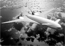
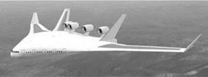
Any extension of payload capability will remain subsonic for the foreseeable future and will lie in the wake of gains made by higher-speed operational success. High-capacity operations will remain around the size of the Airbus 380. Further size increases will use the benefits of a blended wing body (BWB) because the wing – root thickness would be sufficient to permit merging (Figure 1.15) with the fuselage, thereby benefiting from the fuselage’s contribution to lift (see Section 3.20 for BWB configurational advantages). Another alternative would be that of the joined-wing concept (Figure 1.16). Studies of twin-fuselage, large transport aircraft also have shown potential.

Both operators and manufacturers will be alarmed if the price of fuel con­tinues to rise to a point where the air transportation business finds it difficult to sustain operations. The industry would demand that power plants use alternative fuels such as biofuel, liquid hydrogen (LOH), and possibly nuclear power for large transport aircraft covering long ranges. Aircraft fueled by LOH have been used in experimental flying for some time, and fossil fuel mixed with biofuel is currently being flight-tested.

A new type of vehicle known as a ground-effect vehicle is a strong candidate for carrying a large payload (e. g., twice that of the Boeing 747) and flying close to the

Civil Aircraft Design: Future TrendsFigure 1.15. Blended wing body air­craft (Airbus)

Figure 1.16. Joined-wing aircraft (Airbus)

Civil Aircraft Design: Future Trendssurface, almost exclusively over water (Figure 1.17). (A ground-effect vehicle is not really new: The Russians built a similar vehicle called the “Ekranoplan,” but it did not appear in the free market economy.)

Smaller Bizjets and regional jets will morph, and unfamiliar shapes may appear on the horizon, but small aircraft in personal ownership used for utility and plea­sure flying are likely to revolutionize the concept of flying through their popularity, similar to how the automobile sector grew. The revolution will occur in short-field capabilities, as well as vertical takeoffs, and safety issues in both design and oper­ation. Smaller aircraft used for business purposes will see more private ownership to stay independent of the more cumbersome airline operations. There is a good potential for airparks to grow. The NASA, the U. S. Department of Transporta­tion (USDOT), FAA, industry stakeholders, and academia have joined forces to pursue a National General Aviation Roadmap leading to a Small Aircraft Trans­portation System (SATS). This strategic undertaking has a 25-year goal to bring the next generation of technologies to and improve travel between remote communities and transportation centers in urban areas by utilizing the nation’s 5,400 public-use general-aviation airports (United States). The density of these airfields in Europe is much higher. The major changes would be in system architecture through miniatur­ization, automation, and safety issues for all types of aircraft.

Current Military Aircraft Design Trends

This extended section of the book can be found on the Web at www. cambridge .org/Kundu and gives a brief overview of today’s military aircraft design trends, cov­ering typical cost frame, operational roles, and design challenges. Figure 1.10 shows the Antanov A70. Figure 1.11 shows (a) F117 Nighthawk, (b) F22 Raptor, and B2 Bomber.

Figure 1.10. Antanov A70

Figure 1.11. Current combat aircraft

1.2 Future Trends

One does not have to be a prophet to predict near-future trends in the next two to three decades – the same time-frame during which younger readers will begin their career and prepare for the challenges required. It is clear that the vehicle-capability boundaries will be pushed to the extent permitted by economic and defense factors and infrastructure requirements (e. g., navigation, ground handling, and support, etc.). It is no exception from past trends that speed, altitude, and payload will be expanded in both civil and military capabilities. Reference [7] provides cover­age on the aircraft-design process in the next few decades. In technology, smart

Figure 1.12. Supersonic transport aircraft

Current Military Aircraft Design Trendsmaterial (e. g., adaptive structure) will gain ground, microprocessor-based sys­tems will advance to reduce weight and improve functionality, and manufactur­ing methodology will become digital. However, unless the price of fuel increases beyond affordability, investment in aerodynamic improvement will be next in priority.

Readers are advised to search various Web sites for information on this topic.

Current Civil Aircraft Design Trends

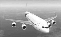
Current commercial transport aircraft in the 100- to 300-passenger classes all have a single slender fuselage, backward-swept low-mounted wings, two underslung wing – mounted engines, and a conventional empennage (i. e., a horizontal tail and a vertical tail); this conservative approach is revealed in the similarity of configuration. The similarity in larger aircraft is the two additional engines; there have been three – engine designs but they were rendered redundant by variant engine sizes that cover the in-between sizes and extended twin operations (ETOPS).

Figure 1.7. Boeing Sonic Cruiser


Current Civil Aircraft Design Trends

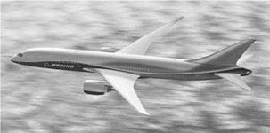
Boeing tried to break the pattern with a “Sonic Cruiser” (Figure 1.7) that proved, at best, to be a premature concept. Boeing returned with the Boeing 787 Dreamliner (Figure 1.8) as a replacement for its successful Boeing 767 and 777 series, aiming at competitive economic performance; however, the configuration remains conventional.

The last three decades witnessed a 5 to 6% average annual growth in air travel, exceeding 2 x 10⁹ revenue passenger miles (rpms) per year. Publications by the International Civil Aviation Organization (ICAO), National Business Aviation Association (NBAA), and other journals provide overviews of civil aviation eco­nomics and management. The potential market for commercial aircraft sales is on the order of billions of dollars per year. However, the demand for air travel is cycli­cal and – given that it takes about 4 years from the introduction of a new aircraft design to market – operators must be cautious in their approach to new acquisitions: They do not want new aircraft to join their fleet during a downturn in the air-travel market. Needless to say, market analysis is important in planning new purchases. Chapter 2 briefly addresses market studies.

Current Civil Aircraft Design Trends
Deregulation of airfares has made airlines compete more fiercely in their quest for survival. The growth of budget airlines compared to the decline of established airlines is another challenge for operators. However, the reputation of an aircraft manufacturer significantly influences aircraft sales. When Boeing introduced its 737 twinjet aircraft (derived from the three-engine B727, the best seller at the time), the dominant-selling two-engine commercial transport aircraft were the Douglas DC-9 and BAe 111.1 was employed at Boeing then and remember the efforts by engineers to improve the aircraft. The Boeing 737 series, spanning nearly four decades of pro­duction to this day, has become the best seller in the history of the commercial – aircraft market. Of course, in that time, considerable technological advancements

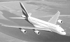
Figure 1.9. Airbus 380


Current Civil Aircraft Design Trends

Подпись: economic performance by abouthave been incorporated, improving the B737’s 50%.

The largest commercial jet transport aircraft, the Airbus 380 (Figure 1.9) made its first flight on April 27, 2005, and is currently in service. The heretofore unchal­lenged and successful Boeing 747, the largest commercial transport aircraft in oper­ation today, now has a competitor.

The gas turbine turboprop offers better fuel economy than to current turbo­fan engines. However, because of propeller limitations, the turboprop-powered aircraft’s cruise speed is limited to about two thirds of the high-speed subsonic turbofan-powered aircraft. For lower operational ranges (e. g., less than 1,000 nau­tical miles [nm], the difference in sortie time would be on the order of less than a half hour, yet there is an approximate 20% saving in fuel cost. If a long-range time delay can be tolerated (e. g., for cargo or military heavy-lift logistics), then large tur­boprop aircraft operating over longer ranges become meaningful. Figure 1.10 shows an Antanov A70 turboprop aircraft.

Current Aircraft Design Status

This section discusses the current status of forces and drivers that control design activities. It is followed by a review of civil and military aircraft design status. Read­ers are advised to search various Web sites on this topic.

1.3.1 Forces and Drivers

The current aircraft design strategy is linked to industrial growth, which in turn depends on national infrastructure, governmental policies, workforce capabilities, and natural resources; these are generally related to global economic-political cir­cumstances. More than any other industry, the aerospace sector is linked to global trends. A survey of any newspaper provides examples of how civil aviation is affected by recession, fuel price increases, spread of infectious diseases, and inter­national terrorism. In addition to its importance for national security, the military aircraft sector is a key element in several of the world’s largest economies. Indeed, aerospace activities must consider the national infrastructure as an entire system. A skilled labor force is an insufficient condition for success if there is no harmo­nization of activity with national policies; the elements of the system must progress in tandem. Because large companies affect regional health, they must share socio­economic responsibility for the region in which they are located. In the next two subsections, civil and military aircraft design status are discussed separately.

The current status stems from the 1980s when returns on investment in classical aeronautical technologies such as aerodynamics, propulsion, and structures began to diminish. Around this time, however, advances in microprocessors enabled the miniaturization of control systems and the development of microprocessor-based automatic controls (e. g., FBW), which also had an additional weight-saving bene­fit. Dramatic but less ostensive radical changes in aircraft management began to be embedded in design. At the same time, global political issues raised new concerns as economic inflation drove man-hour rates to a point at which cost-cutting measures became paramount. In the last three decades of the twentieth century, man-hour rates in the West rose four to six times (depending on the country), resulting in aircraft price hikes (e. g., typically by about six times for the Boeing 737) – accom­panied, of course, by improvements in design and operational capabilities. Lack of economic viability resulted in the collapse or merger/takeover of many well-known aircraft manufacturers. The number of aircraft companies in Europe and North America shrunk by nearly three quarters; currently, only two aircraft companies (i. e., Boeing and Airbus in the West) are producing large commercial transport air­craft. Bombardier Aerospace has risen rapidly to the third largest in the West and recently entered the large-aircraft market with an aircraft capacity of more than 100 passengers. Embraer of Brazil has also entered in the market.

Over time, aircraft operating-cost terminologies have evolved and currently, the following are used in this book (Section 16.5 gives details).

IOC – Indirect Operating Cost: Consists of costs not directly involved with the sortie (trip)

COC – Cash Operating Cost: Consists of the trip (sortie) cost elements FOC – Fixed Operating Cost: Consists of cost elements even when not flying DOC – Direct Operating Cost: = COC + FOC TOC – Total Operating Cost: = IOC + DOC

Because there are variances in definitions, this book uses these standardized defini­tions.

With rising fuel prices, air travelers have become cost-sensitive. In commercial aircraft operations, the DOC depends more on the acquisition cost (i. e., unit price) than on the fuel cost (2000 prices) consumed for the mission profile. Today, for the majority of mission profiles, fuel consumption constitutes between 15% and 25% of the DOC, whereas the aircraft unit price contributes between three and four times as much, depending on the payload range [5]. For this reason, manufacturing considerations that can lower the cost of aircraft production should receive as much attention as the aerodynamic saving of drag counts. The situation would change if the cost of fuel exceeds the current airfare sustainability limit (see Section 1.7 and Chapter 16). The price of fuel in 2008 was approaching the limit when drag – reduction efforts were regaining ground.

A major concern that emerged in the commercial aircraft industry from the mar­ket trend and forecast analysis of the early 1990s was the effect of inflation on air­craft manufacturing costs. Airline operators conveyed to aircraft manufacturers that unless the acquisition cost was lowered by a substantial margin, growth in air-traffic volume would prove difficult. In addition to this stringent demand, there was fierce competition among aircraft manufacturers and their subcontractors. Since the mid – 1990s, all major manufacturers have implemented cost-cutting measures, as have the subcontracting industries. It became clear that a customer-driven design strategy is the best approach for survival in a fiercely competitive marketplace. The paradigm of “better, farther, and cheaper to market” replaced, in a way, the old mantra of “higher, faster, and farther” [6]. Manufacturing considerations came to the forefront of design at the conceptual stage and new methodologies were developed, such as DFM/A and Six Sigma.

The importance of environmental issues emerged, forcing regulatory authorities to impose limits on noise and engine emission levels. Recent terrorist activities are forcing the industry and operators to consider preventive design features.

The conceptual phase of aircraft design is now conducted using a multidis­ciplinary approach (i. e., concurrent engineering), which must include manufac­turing engineering and an appreciation for the cost implications of early deci­sions; the “buzzword” is integrated product and process development (IPPD). Chapter 2 describes typical project phases as they are practiced currently. A chief designer’s role has changed from telling to listening; he or she synthesizes infor­mation and takes full command if and when differences of opinion arise. Margins of error have shrunk to the so-called zero tolerance so that tasks are done right the first time; the Six Sigma approach is one management tool used to achieve this end.

Brief Historical Background

This section provides a compressed tour of history, which I hope will motivate indi­viduals to explore human aerial achievements in more detail. Many books cover the broad sweep of aeronautical history and many others depict particular cases such as famous people and their achievements in aeronautics ([1] is a good place to start). Innumerable Web sites on these topics exist; simply enter keywords such as Airbus, Boeing, or anything that piques your curiosity.

The desire to become airborne is ancient and it is reflected in our imagination and dreams. In the West, Daedalus and Icarus of Greek mythology were the first aviators; in the East, there are even more ancient myths – with no crashes. In Indian mythology, Pakshiraj is a white stallion with wings; the Greeks had a flying horse called Pegasus; and the Swedes also have flying horses. Garuda of Indonesia – half man and half bird – is another example from the Ramayana epic. Middle Eastern and South Asiatic “flying carpets” are seen in many Western cartoons and films. These contraptions are fully aerobatic with the ability to follow terrain; there are no seat belts and they can land inside rooms as well as on rooftops. Recreational possibilities and military applications abound!

Unfortunately, history is somewhat more “down to earth” than mythology, with early pioneers leaping from towers and cliffs, only to leave the Earth in a differ­ent but predictable manner because they underestimated the laws of nature. Our dreams and imagination became reality only about 100 years ago on December 17, 1903, with the first heavier-than-air flight by the Wright brothers. Yet, man first landed on the Moon about three decades ago, less than 70 years after the first powered flight.

The first scientific attempts to design a mechanism for aerial navigation were by Leonardo da Vinci (1452-1519) – he was the true grandfather of modern aviation, even if none of his machines ever defied gravity (Figure 1.1). He sketched many contraptions in his attempt to make a mechanical bird. However, birds possess such refined design features that the human path into the skies could not take that route; da Vinci’s ideas contradicted the laws of nature.

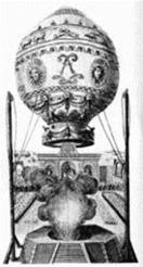
Подпись: Figure 1.2. Montgolfier balloon
Brief Historical Background

After da Vinci, and after an apparent lull for more than a century, the next prominent name is that of Sir Isaac Newton (1642-1727). Perhaps we lack the doc­umentary evidence for I am convinced that human fascination with and endeavor for flight did not abate. Newton developed a theory of lift that although erroneous for low-speed flows, actually has some hypersonic application (although, of course, this was beyond his seventeenth-century understanding of fluid mechanics). Flight is essentially a practical matter, so real progress paralleled other industrial develop­ments (e. g., isolating gas for buoyancy).

In 1783, de Rozier and d’Arlandes were the first to effectively defy gravity, using a Montgolfier (France) balloon (Figure 1.2). For the first time, it was possi­ble to sustain and somewhat control altitude above the ground at will. However, these pioneers were subject to the prevailing wind direction and therefore were limited in their navigational options. To become airborne was an important land­mark in human endeavor. The fact that the balloonists did not have wings does not diminish the importance of their achievement. The Montgolfier brothers (Joseph and Etienne) should be considered among the fathers of aviation. In 1784, Blan­chard (France) added a hand-powered propeller to a balloon and was the first to make an aerial crossing of the English Channel on July 15,1765. Jules Verne’s fic­tional trip around the world in eighty days in a balloon became a reality when Steve Fossett circumnavigated the globe in fewer than fifteen days in 2002 – approximately three centuries after the first balloon circumnavigation.

In 1855, Joseph Pline was the first to use the word aeroplane in a paper he wrote proposing a gas-filled dirigible glider with a propeller.

Tethered kites flew in the Far East for a long time – in China, 600 B. C. How­ever, in 1804, Englishman Sir George Cayley constructed and flew a kite-like glider (Figure 1.3) with movable control surfaces – the first record of a successful heavier – than-air controllable machine to stay freely airborne. In 1842, English engineer Samuel Henson secured a patent on an aircraft design that was driven by a steam engine.

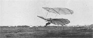
With his brother Gustav, Otto Lilienthal was successfully flying gliders (Fig­ure 1.4) in Berlin more than a decade (ca. 1890) before the Wright brothers’ first

Figure 1.3. Cayley’s kite glider


Brief Historical Background

experiments. His flights were controlled but not sustained. The overestimation of the power requirement for sustained flight (based on work by Sir Isaac Newton, among others) may have discouraged the attempts of the best enginemakers of the time in Germany to build an aircraft engine – it would have been too heavy. Sadly, Lilienthal’s aerial developments ended abruptly and his experience was lost when he died in a flying accident in 1896.

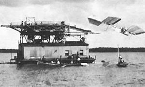
The question of who was the first to succeed naturally attracts a partisan spirit. The Wright Brothers (United States) are recognized as the first to achieve sustained, controlled flight of a heavier-than-air manned flying machine. Before discussing their achievement, however, some “also-rans” deserve mention (see various related Web sites). It is unfair not to credit John Stringfellow with the first powered flight of an unmanned heavier-than-air machine, made in 1848 in England. The French­man Ader also made a successful flight in his “Eole.” Gustav Weisskopf (White­head), a Bavarian who immigrated to the United States, claimed to have made a sustained, powered flight [2] on August 14,1901, in Bridgeport, Connecticut. Karl Jatho of Germany made a 200-ft hop (longer than the Wright Brothers first flight) with a powered (10-HP Buchet engine) flight on August 18,1903. At what distance a “hop” becomes a “flight” could be debated. Perhaps most significant are the efforts of Samuel P. Langley, who made three attempts to get his designs airborne with a pilot at the controls (Figure 1.5). His designs were aerodynamically superior to the Wright flyer, but the strategy to ensure pilot safety resulted in structural fail­ure while catapulting from a ramp toward water. (A replica of Langley’s aircraft was successfully flown from a conventional takeoff.) His model aircraft were flying successfully since 1902. The breaking of the aircraft also broke Professor Langley – a short time afterward, he died of a heart attack. The Wright Brothers were mere bicycle mechanics without any external funding, whereas Professor Langley was a highly qualified scientist whose project had substantial government funding.

Brief Historical Background
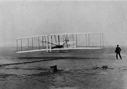
The discussion inevitably turns to the Wright Brothers. Their aircraft (Fig­ure 1.6) was inherently unstable but – good bicycle manufacturers that they were – they understood that stability could be sacrificed if sufficient control authority was maintained. They employed a foreplane for pitch control, which also served as a stall-prevention device – as today’s Rutan-designed aircraft have demonstrated.

Figure 1.5. Langley’s catapult launch

Brief Historical BackgroundExactly a century later, a flying replica model of the Wright flyer failed to lift off on its first flight. The success of the Wright Brothers was attributed to a freak gust of wind to assist the liftoff. A full-scale nonflying replica of the Wright flyer is on display at the Smithsonian Museum in Washington, DC, and the exhibit and others are well worth a trip.

Strangely, the Wright Brothers did not exploit their invention; however, hav­ing been shown that sustained and controlled flight was possible, a new genera­tion of aerial entrepreneurs quickly arose. Newer inventions followed in succession by pioneering names such as Santos Dumas, Bleriot, and Curtis, and the list grew rapidly. Each inventor presented a new contraption, some of which demonstrated genuine design improvements. Fame, adventure, and “Geftihl” (feelings) were the drivers; the first few years barely demonstrated any financial gain except through “joy rides” and air shows – spectacles never seen before then and still just as appeal­ing to the public now. It is interesting to observe the involvement of brothers from the eighteenth to the twentieth century – the Montgolfiers, du Temples, Lilienthas, and Wrights – perhaps they saw the future potential and wanted to keep progress confidential, and who can be better trusted than a brother?

Brief Historical Background

It did not take long to demonstrate the advantages of aircraft, such as in mail delivery and military applications. At approximately 100 miles per hour (mph), on average, aircraft were traveling three times faster than any surface vehicle – and in straight lines. Mail was delivered in less than half the time. The potential for mili­tary applications was dramatic and well demonstrated during World War I. About a decade after the first flight in 1903, aircraft manufacturing had become a lucrative business. I am privileged to have started my own aeronautical engineering career

with Short Brothers and Harland (now part of the Bombardier Aerospace group), a company that started aircraft manufacturing by contracting to fabricate the Wright designs. The company is now the oldest surviving aircraft manufacturer still in oper­ation. In 2008, it celebrated its centenary, the first aircraft company ever to do so.

The post-World War I aircraft industry geared up in defense applications and in civil aviation, with financial gain as the clear driver. The free-market economy of the West contributed much to aviation progress; its downside, possibly reflecting greed, was under-regulation. The proliferation showed signs of compromise with safety issues, and national regulatory agencies quickly stepped in, legislating for manda­tory compliance with airworthiness requirements. Today, every nation has its own regulatory agency. The FAA in the United States and the Joint Aviation Authority (JAA) in Europe (recently renamed EASA) are the most recognized.

Early aircraft design was centered on available engines, and the size of the air­craft depended on the use of multiple engines. The predominant material used was wood. The combination of engines, materials, and aerodynamic technology enabled aircraft speeds of approximately 200 mph; altitude was limited by human physiology. Junker demonstrated the structural benefit of thick wing sections and metal con­struction. In the 1930s, Durener Metallwerke of Germany introduced duralumin, with higher strength-to-weight ratios of isotropic material properties, and dramatic increases in speed and altitude resulted. The introduction of metal brought a new dimension to manufacturing technology. Structure, aerodynamics, and engine devel­opment paved the way for substantial gains in speed, altitude, and maneuvering capabilities. These improvements were seen preeminently in World War II designs such as the Supermarine Spitfire, the North American P-51, the Focke Wolfe 190, and the Mitsubishi Jeero-Sen. Multiengine aircraft also grew to sizes never before seen.

The invention of the jet engine (independently by Whittle of the United King­dom and von Ohain of Germany) realized the potential for unheard-of leaps in speed and altitude, resulting in parallel improvements in aerodynamics, materials, structures, and systems engineering. A better understanding of supersonic flow and a suitable rocket engine made it possible for Chuck Yeager to break the sound bar­rier in a Bell X1 in 1949. (The record-making aircraft is on exhibit at the Smithsonian Air and Space Museum in Washington, DC.)

Less glamorous multiengine heavy-lifters were slower in progress but with no less success. Tens of thousands of the Douglas C-47 Dakota and Boeing B17 Flying Fortress were produced. Postwar, the De Havilland Comet was the first commercial jet aircraft in service; however, plagued by several tragic crashes, it failed to become the financial success it promised. (The first Comet crash occurred at Dum Dum, near Calcutta, in 1952, in a monsoon storm. At that time, I lived about 12 miles from the crash site.)

The 1960s and 1970s saw rapid progress with many new commercial and mili­tary aircraft designs boasting ever-increasing speed, altitude, and payload capabil­ities. Scientists made considerable gains in understanding the relevant branches of nature: in aerodynamic [3] issues concerning high lift and transonic drag; in mate­rials and metallurgy, improving the structural integrity; and in significant discov­eries in solid-state physics. Engineers made good use of the new understanding. Some of the outstanding designs of those decades emerged from the Lockheed

Company, including the F104 Starfighter, the U2 high-altitude reconnaissance air­craft, and the SR71 Blackbird. These three aircraft, each holding a world record of some type, were designed in Lockheed’s Skunk Works, located at the Los Ange­les airport, under the supervision of Clarence (Kelly) Johnson, who graduated from the University of Michigan (my alma mater). I recommend that readers study the design of the nearly 40-year-old SR71, which still holds the speed-altitude record for aircraft powered by air-breathing engines.

During the late 1960s, the modular approach to gas turbine technology gave aircraft designers the opportunity to match aircraft requirements (i. e., mission spec­ifications and economic considerations) with “rubberized” engines. This was an important departure from the 1920s and 1930s, when aircraft sizing was based around multiples of fixed-size engines. The core high-pressure gas turbine module could now be integrated with an appropriate low-pressure compressor, and turbine modules could offer designs with more than 50% thrust variation from the largest to the smallest in a family of derivatives. This advancement resulted in the develop­ment of families of aircraft design. Plugging the fuselage and, if necessary, allowing wing growth covered a wider market area at a lower development cost because con­siderable component commonality could be retained in a family: a cost-reduction design strategy – that is, “design one and get the other at half price.”

Rocket-powered aircraft first appeared during World War II. The advent and success of the Rutan-designed Space Ship One in 2004 (see Figure 1.14) to the fringes of the atmosphere will certainly bring about the large market potential of rocket-powered airplanes. Rocketry first entered the Western European experience when Tippu Sultan used rockets against the British-led Indian army at the Battle of Srirangapatnum in 1792. The propellants were based on a Chinese formula nearly a thousand years old. Many people are unaware that the experience of Tippu’s rock­ets led the British to develop missiles at the Royal Laboratory of Woolwich Arsenal, under the supervision of Sir William Congrave, in the late eighteenth century. Von Braun [4] mentions that he took the idea from Tippu’s success for his V2 rocket, paving the way for today’s achievement in space flight as an expanded envelope beyond winged flight vehicles.

There was a time when designers could make sketches to generate candidate configurations, sometimes stretching to exotic “star-wars” shapes; gradually, how­ever, creating ideas with a pencil has diminished. Capitalistic objectives render designers quite conservative, forcing them to devote considerably more time to anal­ysis. The next section discusses why commercial aircraft designs are similar, with the exception of a few one-off, special-purpose vehicles. Military designs emerge from more extensive analysis – for example, the strange-looking Northrop F117 is config­ured using stealth features to minimize radar signature. Now, more matured stealth designs look conventional; however, some aircraft are still exotic (e. g., the Lockheed F22).

Introduction

1.1 Overview

This book begins with a brief historical introduction in which our aeronautical legacy is surveyed. The historical background illustrates the human quest to con­quer the sky and is manifested in a system shaping society as it stands today: in com­merce, travel, and defense. Its academic outcome is to prepare the next generation for the advancement of this cause.

Some of the discussion in this chapter is based on personal experience and is shared by many of my colleagues in several countries; I do not contest any dif­ferences of opinion. Aerospace is not only multidisciplinary but also multidimen­sional – it may look different from varying points of view. Only this chapter is written in the first person to retain personal comments as well as for easy reading.

Current trends indicate maturing technology of the classical aeronautical sci­ences with diminishing returns on investment, making the industry cost-conscious. To sustain the industry, newer avenues are being searched through better manu­facturing philosophies. Future trends indicate “globalization,” with multinational efforts to advance technology to be better, faster, and less expensive beyond exist­ing limits.

1.1.1 What Is to Be Learned?

This chapter covers the following topics:

Подпись: Section 1.2: Section 1.3: Section 1.4: Section 1.5: Section 1.6: Section 1.7:A brief historical background

Current design trends for civil and military aircraft

Future design trends for civil and military aircraft

The classroom learning process

Units and dimensions

The importance of cost for aircraft designers

1.1.2 Coursework Content

There is no classroom work in this chapter, but I recommend reading it to motivate readers to learn about our inheritance. Classwork begins in Chapter 6 (except for the mock market survey in Chapter 2).

Figure 1.1. Da Vinci’s flying machine

Use of Semi-empirical Relations

DATCOM (U. S.) and RAE data sheets (U. K., recently replaced by ESDU) have served many generations of engineers for more than a half century and are still in use. Over time, as technology has advanced, new tools using computer-aided engi­neering (CAE) have somewhat replaced earlier methods.

Semi-empirical relations and graphs cannot guarantee exact results; at best, error-free results are coincidental. A user of semi-empirical relations and graphs must be aware of the extent of error that can be incurred. Even when providers of semi-empirical relations and graphs give the extent of error range, it is difficult to substantiate any errors in a particular application. Other methods could provide better results.

If test results are available, they should be used instead of semi-empirical rela­tions and graphs. Tests (e. g., aerodynamics, structures, and systems) are expensive to conduct, but they are indispensable to the process. Certifying agencies impose mandatory requirements on manufacturers to substantiate their designs with test results. These test results are archived as a databank to ensure that in-house semi­empirical relations are kept “commercial in confidence” as proprietary information. CFD and FEM are the priority, before semi-empirical relations and graphs. The consistency of CFD in predicting drag (see Chapter 14) has to be proven conclu­sively when semi-empirical relations and graphs are used extensively. This also is true for weight prediction.

This book does not include many of the DATCOM/ESDU semi-empirical rela­tions and graphs. Inclusion will prove meaningless unless their use is shown in worked-out examples. Typically, their use during conceptual studies can be post­poned until the next phase of study (see Chapter 2), which is beyond the scope of this book. It is important for instructors to compile as many test data as possible in their library of resources.

Suggestions for the Class

Coursework starts with a mock market survey to get a sense of how an aircraft design is conceived (its importance is highlighted in Section 2.3). Inexperienced stu­dents depend on instruction; therefore, a teacher’s role is important at the begin­ning. Here, I offer some of my experiences in the hope that they may be helpful.

The teacher divides the class into groups of four, which then work as teams. After introducing the course content and expectations, the teacher assigns (with student participation) the type of aircraft to be undertaken in the coursework (the example of the Learjet 45 class of aircraft is used in this book). The teacher gives the students the payload and range for the aircraft and asks them to list what they think are the requirements from the operator’s (customer’s) perspective and directs them to produce a scaled three-view sketch. I recommend that students consult Aerospace America [23] to study similar designs and tabulate the statistical data to arrive at their proposition. (Relevant Web sites also provide substantial informa­tion.) Understandably, in most cases, the specifications and concept configuration designs may not be realistic; however, some students could arrive at surprisingly advanced concepts.

It is unrealistic to assume full understanding by students at the start of the design exercise, but I have found that comprehension of task obligations improves rapidly. The teacher explains the merits and demerits of each team’s proposition, retaining only the best cases. Finally, the teacher selects one configuration (after pooling ideas from the groups) but allows the students to retain configuration differences (e. g., high or low wing, or tail position) that have been tailored to a realistic shape and will be systematically fine tuned as the class progresses to the final design. When specifi­cations have been standardized and the configurations decided, the class assumes a smooth routine. I recommend that the teacher encourage differences among config­urations to compare the designs at the end of the semester. The comparison of the final design with their initial propositions, as the evidence of the learning process, will provide students with satisfaction.

This type of project work does not have closed-book final examination – grades are based on project documents submitted by students. Grading is at the discre­tion of the teacher, as it should be, but peer review contributes. Working in teams requires honest feedback among students because the teacher cannot track individ­uals working on their own. Leadership qualities of individual students should be recognized but should not overshadow a quieter student’s performance. The stu­dents will soon be competing in the reality of the industry, and a spirit of teamwork must be experienced in the classroom. This spirit is not only about cooperation with others; it also is about being an effective contributing member working in harmony within a team. By this time, the teacher would have adequate feedback on individual work quality and capability.

A note of caution: What is accomplished in 36 hours of classroom lectures takes approximately 36 weeks in industry, not including the work put in by the experi­enced engineers engaged in the work. The undergraduate coursework must stay on schedule to conclude on time. Therefore, to maintain the schedule, the teacher must remain in close contact with students.

Road Map of the Book

The Arrangement

In a step-by-step manner, I have developed an approach to aircraft design method­ology at the conceptual stage that can be followed in the classroom, from the initial stages of finding a market to the final stages of freezing the aircraft configuration. In the aircraft industry, after the “go-ahead” is obtained, the development program moves to the next phase (i. e., the Project [or Product] Definition Phase), which is not within the scope of this book. The book covers two semesters of work: the first, from Chapters 1 through 13, encompasses the conceptual design; and the second, from Chapters 14 through 17, deals with a more detailed exposition of the first semester’s work, advancing the concept through more analysis. Some of the second-semester work on cost and manufacturing considerations may require outside, aeronautical – school assistance. The recommended two-semester curriculum is outlined at the end of this road map.

The chapters are arranged linearly; there is not much choice in tailoring a course. I attempt to keep the treatise interesting by citing historical cases. The main driver for readers is the motivation to learn. Except for Chapter 1, the book is writ­ten in the third person. (Actual coursework starts in Chapter 6 after a brief mock market survey by the students, as discussed in Chapter 2.)

I omit discussions of vertical takeoff and landing/short takeoff and landing (VTOL/STOL), as well as helicopters in their entirety – these subjects require their own extensive treatment.

Aircraft design is a rigorous discipline with a conservative approach – it is not schoolday fantasies of exotic Star Wars shapes. It is essential to learn the basics through conventional designs and then move on to innovations after mastering these basics. Coursework methodology should be in harmony with industrial practices; otherwise, the gap between academia and industry (mentioned previously) would interfere. Using computational fluid dynamics (CFD) during conceptual study is now a routine industrial practice to establish a baseline configuration and must be introduced to students so that they may appreciate the capabilities of CFD. I am aware that the introduction to CFD comes late in undergraduate study and, therefore, its use is postponed until the second semester or, even better, until post­graduate project work, assuming that students will be familiar with CFD by then.

I recommend the use of computer-aided drawing (CAD) in generating configura­tions, which facilitates any subsequent CFD work. These aspects of the classroom learning process are discussed in further detail in Section 1.5.

What, specifically, does this book offer? The road map of the book is described as follows. Chapter 1 is purely introductory – no coursework is embedded in it. It serves as a “starter course,” intended for easy reading written in the first person. To a newcomer, some statements may appear unsubstantiated, but rest assured that they have been well tested by my colleagues in various countries and companies – the facts will be revealed as progress is made. Chapter 1 begins with a brief histor­ical outline intended to inspire readers’ interest in our aerospace heritage (one of the few areas in which reality can be more interesting than fiction). The fascinating stories of human achievement are motivational, and I urge students to read books and peruse Internet Web sites that are dedicated to aerospace history. They cover the full range of human emotions: from disappointment due to failures and fatali­ties to the joy of successes; from light-hearted circus flying to flying in spectacular display that defies imagination. Chapter 1 continues with a description of typical current designs and associated market drivers. Next, I look into the future, ending the chapter with units and dimensions used in design practice.

Marketing and airworthiness are the two most important requirements that shape a product. Chapter 2 describes typical project phases as generic procedures for aircraft design: from the conceptual stage to the finished product. It continues with a discussion of the importance of market information. Students are encour­aged to conduct a short mock market study to generate a specification for which experienced guidance is required. For commercial aircraft, the specification is pri­marily the mission profile for the payload range capability. The differences between military and civil aircraft specifications and the associated financial outlay are sig­nificant. Military specifications are substantially more complex, depending on the specific combat role: They vary widely, and complexity spirals when multirole capa­bilities are required. Substantiation of airworthiness regulations is mandatory in the industry and also is discussed in Chapter 2. The U. S. Federal Aviation Regulations (FAR) are now in wide use, and I adhere to them. The recently established Euro­pean Aviation Safety Agency (EASA) standards are similar to FAR and therefore are not discussed here.

Aerodynamic considerations are central to shaping a streamlined aircraft con­figuration. Therefore, aerodynamic considerations are introduced in Chapter 3 to expose students to what is needed for the aircraft design course. Extensive treat­ment of aerodynamics is provided separately in all aeronautical schools; here, only the necessary aerodynamic information has been compiled for reference as the air­craft design coursework progresses. Crucial aerofoil aerodynamics information is provided in Chapter 3 and characteristics are found in Appendix C. Chapter 3 does not provide sequential coursework to start with, but students are required to know the facts and to refer to and apply them when required.

Following the history of achievements are the statistics, covered in Chapter 4. As mentioned previously, products from different origins show similarities that indi­cate a strong statistical pattern that provides an idea of what is to be expected in a new design. A new design, with commercial considerations, must be a cautious progression, advancing through the introduction of the latest proven technologies.

It is not surprising, therefore, to observe a strong statistical correlation with the past. Military aircraft designs necessarily must be bolder and make bigger leaps to stay decisively ahead of potential adversaries, regardless of the cost. Eventu­ally, older, declassified military technology trickles down to commercial use. One example is fly-by-wire (FBW) technology. Chapter 4 also discusses various possi­ble aircraft component configurations currently in use to assist in rational selec­tion. Jane’s All the World’s Aircraft Manual (published annually) is an indispens­able source for vital aircraft statistics and has served many generations of aero­nautical engineers around the world for more than half a century. Chapter 4 is intended to be a data source for aircraft design, and students will refer to it as coursework progresses. This information is provided early in the book so that expec­tations for new designs can benefit from the experiences of past designs. Chap­ter 5 addresses the aircraft speed envelope (i. e., the V-n diagram).

Formal, conceptual aircraft design work starts in Chapter 6, following the release of a market specification as discussed in Chapter 2. Civil and military aircraft configurations are discussed separately because they are so different in approach. Students must retrieve information from previous chapters to configure their air­craft. Chapter 6 addresses the fuselage, the shape of the wing, the empennage, the engine positions, and so forth and provides candidate aircraft configurations with definite geometric dimensions that meet market requirements. The aircraft concep­tual design must consider offering a family of variants to cover a wider market at low cost by retaining significant component commonalities. This point is empha­sized throughout the book. Considering families of variants must begin at the initial stage to make products right the first time (i. e., the Six Sigma approach).

Chapter 7 sizes and locates the undercarriage for the configurations arrived at in Chapter 6. Next in the sequence, Chapter 8 discusses component and aircraft mass (i. e., weight) estimations and location of the center of gravity (CG) and its move­ment with payload variation. (Chapter 12 discusses the role of the CG position in aircraft static stability.) As demonstrated, weight estimation must be an iterative process because fine tuning the design from past designs presented in Chapters 4 and 6 is otherwise merely a guess. Chapter 9 addresses the difficult aspect of drag esti­mation for both military and civil aircraft. Successful understanding of these topics is of paramount importance for students. Another emphasis throughout this book is presenting the industry-standard approach to estimate aircraft and the breakdown of component drag.

Relevant information on aircraft power plants is integral to aircraft design. Although this book does not focus on aircraft engine design, aircraft designers should thoroughly understand the propulsion system as the “heart” of the aircraft. Chapter 10 discusses in detail gas turbine and piston engine performance, as well as related topics concerning engine and aircraft integration. This information is neces­sary for shaping nacelles and estimating their installed drag.

When the configuration is finalized, the aircraft mass estimated, the CG located, and the drag polar becomes available, the freezing of configuration by sizing the air­craft for the family concept and finding matched engines to meet customer specifi­cations is described in Chapter 11. This phase closely conforms to industry prac­tices. The procedure offers a “satisfying” solution for the most important sizing parameters, complying with constraints imposed by market specifications. These parameters lead to candidate aircraft configurations. Parametric sensitivity studies are required, which eventually prove to be the key to success through balancing comfort with cost in a fiercely competitive market. Safety is never compromised.

Chapter 12 discusses aircraft static stability, which can affect the overall config­uration in an effort to find a mass distribution that satisfactorily locates the CG. Tail sizing establishes the CG envelope, and iterations typically are required to refine the result. The iteration process should progress quickly by using spreadsheets for repet­itive calculations. Fortunately, aircraft dynamic behavior and control responses are not addressed in the conceptual phase – they are considered after the configuration is finalized. If required later, the control geometries are tailored or adjusted, pos­sibly requiring another iteration to update the configuration. To save time in the classroom, the iterations of control surface tailoring are avoided. The design con­figuration is now complete but still requires fine tuning of the aircraft mass and CG location.

Chapter 13 covers aircraft performance: the proof of the product that demon­strates compliance with the customer’s requirements as listed in the specifications. Another iteration may be required if performance falls short of its goal. The deriva­tion of aircraft performance equations is kept to a minimum because many excellent books on the subject are available.

As previously stated, the first thirteen chapters of this book constitute the cur­riculum for a one-semester preliminary design exercise. However, aircraft design must also consider environmental and safety issues, systems requirements, typical structural layout, manufacturing and assembly (DFM/A) methodology, design, and, most important, cost implications – topics that are addressed in Chapters 15 through 17. These considerations constitute the conceptual design study phase, which under­goes management review for the go-ahead of a project. A second semester could include Chapters 14 through 17, with the discussion of CFD being a significant part of the coursework.

Chapter 14 provides an overview of how CFD is involved during the conceptual – design study phase. This book is not about CFD, which is an exhaustive subject itself to which scientists and engineers can devote their entire careers. Today, almost all undergraduate aeronautical engineering courses introduce CFD in the final year so that students can gain proficiency in application software. If the first semester’s work on aircraft configuration is done using a 3D CAD model, at least time required for aircraft geometry generation can be saved. Undergraduate work is best suited to conventional subsonic jet transport aircraft with simple shapes.

Each chapter of the book starts with an overview, a summary of what is to be learned, and the coursework content. There are no exercises at the end of the chap­ters; each continues the project progression of students.

Many categories of aircraft have been designed; this book covers a wide range for coursework exercises and provides adequate exposure to important categories. After students become proficient, they could then undertake less conventional air­craft designs. Associated examples in the book are the turbofan-powered Learjet 45 class of aircraft for civil applications and a turbofan-powered military, advanced jet trainer aircraft of the Royal Air Force (RAF) Hawk class. Case studies are indis­pensable to the coursework and classroom exercises must be close to actual air­craft that have been modified to maintain “commercial in confidence.” Additional examples in Appendix D are based on actual designs worked out by the author. The results are not from the industry but have been compared with available per­formance data. The industry is not liable for what is presented herein.

The three aircraft cases are (1) a turbofan-powered Learjet 45 class Bizjet; (2) a high-subsonic jet in the Boeing 737/Airbus 320 aircraft class; and (3) a military advanced jet trainer (AJT) in the B. Ae Hawk class, which has a close support – role variant. Designing an F22 class of aircraft is beyond the scope of this book –

1 question whether any textbook can be used for undergraduate coursework with­out first offering an exercise on simpler designs. Nevertheless, advanced work on military designs is possible only when the basics have been mastered – the aim of this book. Developing a configuration within a family concept so that variants can be designed at low cost and cover a wider market area is emphasized. One might even say, “Design one and get the second at half the development cost.” The jet trans­port aircraft is recommended as the most suitable for coursework projects. Chapter

2 lists a few projects of interest to students. Other projects could be extracted from the competitions held by R. Ae. S in the United Kingdom and organizations such as NASA, the FAA, and AIAA in the United States.

For classroom practice, using manual computation is recommended, with spreadsheets developed by students because the repetitive aspect is part of the learning process. It is essential for students to develop a sense for numbers and to understand the labor content of design (it is expensive to make midcourse changes). It is common nowadays to provide CDs with companion software. However, I do not follow this practice because the software for handling repetitive tasks constrains students from interacting more with the governing equations and is part of the learn­ing experience.

If students elect to use off-the-shelf software, then it must be reputable. For U. S. readers, well-circulated NASA programs are available. However, these are more meaningful after the subject of aircraft design is well understood – that is, after completing the coursework using manual computations. This leads to an appreci­ation of how realistic the computer output is, as well as how changes in input to improve results are made. It is better to postpone using conceptual design software until entering the industry or doing postgraduate work. In academia, students can use CFD and finite element method (FEM) analyses to complement the aircraft design learning process.

Flying radio-controlled model aircraft may be interesting to students, but I do not think it is relevant because it is not an industrial practice unless the project concerns radio-controlled aircraft such as remotely piloted vehicles (RPVs) and unmanned air vehicles (UAVs). Some combat aircraft have an unpowered, accu­rately scaled, radio-controlled model dropped from the mother aircraft to test sta­bility behavior. However, if there is interest, students can take up model-aircraft flying as a hobby.

Suggested Route for the Coursework

The author suggests the following path for the two-semester coursework. Each semester entails 36 hours of lecture and coursework: specifically, 12 to 14 hours of lectures by the instructor followed by computational work in class. Any unguided

work may be left for routine computation to complete the assignment of the chapter. The final week of coursework is reserved for report writing. An outline of the final- report requirements may be given to students at the beginning of the course. Stu­dents are required to submit brief preliminary reports at the completion of each chapter so that the instructor can offer improvement guidelines. This reduces stu­dent workload at the end of the semester and enables them to complete their report without loss of quality. The coursework progresses sequentially following the chap­ters of this book.

First Semester

Lecture hours (14)

1. Establish the project specification with a mock market 1

study as described in Chapter 2 (e. g., a 10-passenger,

2,000-nm Bizjet in the Learjet 45 class, the example used throughout this book).

2. Configure the aircraft (Chapter 6 with input from Chapters 2

3 and 4).

3. Select aerofoil and establish wing characteristics. 2

4. Complete undercarriage layout and tire sizing (Chapter 7). 1

5. Estimate component and aircraft weight and determine 1

the CG location (Chapter 8, first iteration).

6. Estimate aircraft drag (Chapter 9). 1

7. Establish engine data (Chapter 10). 1

8. Size the aircraft and find a matched engine (Chapter 11). 1

9. Determine the family of variant design (Chapter 11). 1

10. Evaluate stability considerations. This requires a second 1

iteration to fine tune aircraft weight and accurately locate

the CG position (Chapter 12).

11. Conduct a performance evaluation to check whether the 2

market specification is met (Chapter 13). If it is not, then

fine tune the configuration and engine size, and reiterate the computational process until the performance meets specifications.

Classroom work hours with the instructor: 22 hours total

Classroom management and requirements for submission of work in report form is determined by the instructor.

Second Semester

The second semester continues the work done in the first semester, progressing as follows:

Lecture hours (11)

1. Discuss material and structural considerations and 2

preliminary layout (Chapter 15).

2. Discuss safety and environmental issues (Chapter 15). 1

3. Establish system and instrument requirements (e. g., 2

electrical, mechanical, control, communication navigation)

(Chapter 15).

4. Review of first-semester work in conjuction with 1

information gained so far in the second semester. If

required, refine weights and configuration.

5. Review total airworthiness requirements. 1

6. Discuss manufacturing considerations. 1

7. Discuss cost estimates (e. g., aircraft unit and direct 2

operating costs [DOCs]).

8. Discuss flight and ground test plans. 1

Classroom work hours with the instructor: 22 hours total

Classroom management and requirements for submission of work in report form are determined by the instructor. (CFD [Chapter 14] and FEM analyses are separate tasks and are beyond the scope of this book.)
Aircraft Design

Aircraft Design

This book is about the conceptual phase of a fixed-winged aircraft design project. It is primarily concerned with commercial aircraft design, although it does not ignore military aircraft design considerations. The level of sophistication of the latter is such that were I to discuss advanced military aircraft design, I would quickly devi­ate from the objective of this book, which is for introductory but extensive course – work and which provides a text for those in the industry who wish to broaden their knowledge. The practicing aircraft design engineer also will find the book helpful. However, this book is primarily meant for intensive undergraduate and introductory postgraduate coursework.

A hundred years after the first controlled flight of a manned, heavier-than-air vehicle, we can look back with admiration at the phenomenal progress that has been made in aerospace science and technology. In terms of hardware, it is second to none; furthermore, integration with software has made possible almost anything imaginable. Orville and Wilbur Wright and their contemporaries would certainly be proud of their progenies. Hidden in every mind is the excitement of participating in such feats, whether as operator (pilot) or creator (designer): I have enjoyed both no less than the Wright brothers.

The advancement of aerospace science and technology has contributed most powerfully to the shaping of society, regardless to which part of the world one refers. Sadly, of course, World War II was a catalyst for much of what has been achieved in the past six decades. My career spans the 1960s to the beginning of the twenty-first century, possibly the “golden age” of aeronautics! In that period, investment in the aerospace sector by both government and private organizations led to rapid changes in the acquisition, application, and management of resources. Aerospace design and manufacturing practices were transformed into their present manifestation.

The continuous changes in aircraft design and manufacturing procedures and methodologies have resulted in leaner aerospace infrastructure (sometimes to an “anorexic” level). New graduate-level engineers are expected to contribute to the system almost immediately, with minimal supervision, and to “do it right the first time.” The route to the design office through apprentice training is not open to as many as it once was. Life is now more stressful for both employers and employ­ees than it was the day I started my career: Organizational survivability and con­sequent loyalty are not what they used to be. The singular aim of this book is to prepare readers as much as possible for industry-standard engineering practices. The methodology adopted herein is in line with what is practiced in industry; the simplifications adopted for classroom use are supported by explanations so that an appreciation of industry expectations will not be lost. Aircraft conceptual design necessarily entails an iterative process. In the classroom, one or two iterations should prove sufficient as a time-efficient procedure to refine component sizes and to freeze aircraft configurations.

My student days were almost devoid of any aircraft design book. Wood [1] and Corning [2] were the early books that brought aircraft design into textbook form, followed by an excellent text written by Nicolai [3]. In 1982, Torenbeek [4] covered substantial ground with contemporary treatises in his book. Roskam’s compilation [5] furthered the cause. I have benefited greatly from the works of these five authors. Gradually, more aircraft design books have appeared in the literature [6-18], each with its own strength. There is still considerable scope to advance the subject, specif­ically by preparing new engineers to cope with the demand for a high level of profi­ciency in the industry. (I recommend that readers review the Virginia Tech Web site of aircraft design bibliographies [18]. It is a comprehensive compilation of aircraft design information sources.)

One-third of my career has been spent in academia and two-thirds in aircraft design. I can see a clear gap between academic pursuits and what industry expects from new graduates as finished university “products.” The United States and the United Kingdom are aware of this problem [19-24], and both make periodic recom­mendations. However, the problem is acute in the developing world, where tasks among scientists with advanced degrees and engineers are not as clearly defined as they are in the West. (If I may digress slightly, I have found from personal expe­rience that a major hindrance to progress in some of the developing world comes from the inability to administrate technological goals even when there is no dearth of technical manpower – those who perform better when working in the advanced world. People know about political asylum. However, professional asylum, also known as the “brain drain,” is a real issue. Although design is not accomplished via the democratic process, the design culture should encourage the free sharing of knowledge and liberal distribution of due recognition to subordinates. Lack of accountability in higher offices is a root cause of the failure to exploit the full poten­tial of natural and human resources.) In time, things are changing but unfortunately slower than its potential because higher management still maintains older attitudes that masquerade behind seemingly modern views. Technology can be purchased, but progress has to be earned. I hope to prepare the readers to contribute to the progress.

The roles of scientists and engineers are well defined. According to Von Karman, “A scientist discovers what already exists. An engineer creates what never was” [25]. Converting ideas into reality for customer use proves more difficult than adding any number of publications to a list (except those papers that break new ground or advance a cause that is being adapted to enrich a generation). Perhaps the measure by which to judge scientists should be like that of engineers – namely, how much wealth has the work generated (where wealth is defined in broad terms as all that encompasses the commonweal). It should be clearly understood that scientists and engineers have to work together and not in a fallacious hierarchy in which advanced degrees stand above significant experience. Consider engineers such as

Johnson, Mitchell, and Dassault – these are the people to whom I refer. Today’s engineers must have strong analytical and applied abilities to convert ideas into profitable products. I hope that this book serves this cause by combining analytical methods and engineering practices and adapting them to aircraft design. Prerequi­sites are second-year (U. K.) or junior-level (U. S.) mathematics and aerodynamics. It is not difficult to acquire these prerequisites – simply a semester of effort in a class found in any university syllabus. Of course, by including “experience,” this book offers more than just analysis; aircraft design must be practiced.

Engineering design is a process, and today’s practices have so matured that they demonstrate systematic patterns despite the differences that exist between compa­nies or countries, whether military or civil. The laws that govern the behavior of nature are universal. The differences are in the governing rules and practices of resource acquisition and management. The resulting products within the course still remain in close competition and may even show similarities in presentation and per­formance, not necessarily dependent on any 007 work!

I thank my teachers, supervisors, colleagues, students, shop-floor workers, and all those who taught and supported me during my career. I remember (in no partic­ular order) the late Professor Holt Ashley of Stanford University; Professor Arthur Messiter of the University of Michigan; James Palmer of Cranfield University; Pro­fessor Shankar Lal of the Indian Institute of Technology, where I was Professor; Kenneth Hoefs of the new airplane project group of the Boeing Company, who taught me aircraft sizing and drag estimation; James Fletcher of Short Brothers and Harland, who baptized me into the aircraft industry; Tom Johnston, Director and Chief Engineer of Bombardier Aerospace-Shorts (BAS) who provided con­siderable help in bringing out this book; the late Dr. Vikram Sarabhai, who gave me the opportunity to be associated with the Indian Space Research Organisation; and Wing Commander Baljit Kapur, Chairman of Hindustan Aeronautics Limited (HAL [26]), where I served as the Chief Aircraft Designer. My special thanks to Dr. Tom Cummings of BAS; Noel Weir of Canadair Ltd; Stephen Snyder, formerly of the Boeing Company and now an independent consultant; and B. C. Chamundaiah and the shop-floor workers of HAL, who stood by me during difficult days. I derive tremendous pleasure from teaching and have valued interaction with students in India, Iraq, the United Kingdom, and the United States. They came to me as a bou­quet of flowers. I aver that they have taught me no less than I have taught them. This book reflects the universal demands of students. In their company, I was able to remember my youth.

I am thankful to my former colleagues Colin Elliott, Director of Engineering; David Riordan, Chief Engineer; and James Tweedie, Senior Engineer, BAS, who have helped me bring out an industry-standard book on aircraft design. David’s review work is thankfully acknowledged. The contribution of BAS is gratefully acknowledged. I started my aeronautical career with BAS (then Short Brothers and Harland Ltd.) and, after a long break, rejoined and then retired from the company, the first aerospace company to celebrate its centenary.

The aim of this book is to enable new graduates to seamlessly join the industry in order to become productive as soon as possible. The book also could be used in the industry for training purposes. In today’s world, engineers may need to be retrained in broader disciplines to offer support in areas beyond their main area of special­ization. To ensure continuity and overcome any current deficiencies in a second edition, I will be grateful for readers’ suggestions and criticisms. Please contact the publisher or email the author at a. kundu@qub. ac. uk with any relevant information.

I am indebted to Jane’s All the World Aircraft Manual [27], NASA, Airbus, Saweed, BAE Systems, Hamilton Standard Propellers, Europa Aircraft Company, Dr. John McMasters (Boeing Aircraft Company), Professor Michael Niu, Professor Jan Roskam (DARcorp), Professor Egbert Torenbeek, Dr. Bill Gunston, and the late Dr. L. Pazmany. There are many excellent Web sites in the public domain. I am thankful to Richard. Ferriere. free. fr/3vues, Aerosite, and Virtual Aircraft Museum for permitting me to use some of their diagrams. I gratefully acknowledge the help of many other Web sites. The wisdom of these organizations and people will take the next generation forward with confidence as they substantiate what is learned in classrooms. To familiarize readers with many types of aircraft, I provide dia­grams of various types (some are not operational). I apologize if I have inadver­tently infringed on any proprietary diagrams for educational purposes. For a few of the many diagrams I have collected over the years, the sources have gotten lost. Please forgive me for the error. Any infringement on proprietary information was not deliberate and I hope may be overlooked for the sake of preparing the next gen­eration. If brought to my notice, I will acknowledge sources and make any necessary corrections in the next edition of this book.

I am indebted to many people at The Queen’s University Belfast (QUB) for suggestions on how to improve the quality of this book. They include my present and former colleagues and former students. (I must have done a good job – it is a pleasure to learn from them.) In no particular order, they are Dr. John Watter – son, Dr. Mark Price, Dr. Adrian Murphy, Dr. Simon Hall, Dr. Neil Forsythe, Dr. Rachel Moore, Dr. Brendan Sloan, Damien Quinn, and David Lisk. I typed the entire manuscript and therefore am responsible for any loss of quality in the text due to typographical and grammatical errors. I am grateful to QUB for providing all of the facilities necessary to complete this book.

Peter Gordon, Senior Editor of the respected Cambridge University Press, offered me the finest support throughout the writing of this book. The hard, tire­less work of Eleanor Umali of Aptara gave this book its shape. I offer my personal and heartfelt thanks to both of them and their organizations.

I owe thanks to my grandfather, the late Dr. Kunja Behari Kundu; my father, the late Dr. Kamakhya Prosad Kundu; and my cousin-brother, the late Dr. Gora Chand Kundu. They inspired and motivated me to remain studious. I cannot con­clude without thanking my wife, Gouri. I did not give her much choice, but it was not a problem. She kept me nourished and maintained all domestic systems. When I sometimes pushed to the maximum permissible speed limits – her patience was remarkable.

I was educated in the United Kingdom (Cranfield University and QUB) and in the United States (University of Michigan and Stanford University); I also worked in the United Kingdom (BAS) and in North America (Boeing and Canadair). I have found that nature is the same on both sides of the Atlantic, as is the language. Any differences are trivial. In today’s world of cooperative ventures among countries, es­pecially in the defense sector, the methodologies adopted in this book should apply.

I dedicate this book to both sides of the Atlantic to where I immigrated, and to those who gave me their best education, their best jobs, and their fine homes. I left only to return and take this opportunity to write.