Category Aircraft Flight

Drag due to interference effects

Any intersection between two surfaces such as at the wing-fuselage junction has a disruptive effect on the flow, and extra drag is incurred. Acute angles such as that formed between the wing and fuselage on either high – or low-wing air­craft are worse than oblique angles. A mid-wing position would be better from this aspect, but mid-wing designs introduce structural problems. The cabin crew in a mid-wing airliner might not take kindly to the main spar getting in the way of the drinks trolly.

On a low-wing aircraft, the fuselage can interfere with the pressure distribu­tion on the upper surface of the wing, possibly inducing flow separation. A high-wing configuration is better in this respect, as in this case, the flow on the under-surface is the most affected. The under-surface flow is normally in a favourable pressure gradient, and is thus less likely to separate. The high wing arrangement has a number of disadvantages, however, including problems involved in trying to avoid long undercarriage legs, and adverse interference effects between the wing wake and the tailplane. Notice the very high mount­ing position of the horizontal tail surface on the C-17 (Fig. 10.20), and the BAe 146 (Fig. 6.26). This is necessary, in order to keep the tailplane out of the wake of the wing at high angles of attack.

The wing-fuselage interference effect is largely a manifestation of the gap in the spanwise lift distributing mentioned above (Fig. 4.11), and can be reduced by use of a lifting fuselage as on the MiG-29 (Fig. 4.12), where the interference effect is also reduced by use of a blended wing-fuselage. A blended wing-fuselage was also used on the SR-71 Blackbird spy-plane (Fig. 6.40). In this case, the arrangement has the important advantage that the elimination of sharp junctions reduces the aircraft’s radar signature. Interference effects can also be reduced by means of wing fillets, but this feature is rarely found on modern aircraft.

A more radical solution to the interference problem is to remove most of the junctions by adopting an all-wing configuration as in the B2 ‘Spirit’ (Fig. 4.19). Large slender-delta-winged aircraft lend themselves to a nearly all-wing con­figuration, and such an arrangement was considered at the early stages of the Concorde project. The idea was eliminated because it would have required a very large aircraft, in order to provide sufficient cabin depth, and would have introduced another set of novel features in an already revolutionary design. It was also realised, that passengers would react unfavourably to the idea of having traditional port-holes replaced by overhead fanlights.

The last item in the drag budget is the undercarriage. Despite the consider­able added cost and weight of a retracting undercarriage, the benefits are so great, that fixed undercarriages are rarely used on anything other than small light aircraft. An interesting solution to the problem of undercarriages is that used on the Quickie shown in Fig. 11.9. The canard foreplane has pronounced anhedral, and also serves as the undercarriage legs. The Rutan Vari-Eze shown in Fig. 4.20 uses a retractable nose wheel which is also lifted for parking, as shown. Retracting the nose wheel saves a considerable amount of drag, and the pilot would probably get away with forgetting to lower it on landing; a com­mon error with amateur pilots.

Drag due to interference effects

Fig. 4.19 All Wing, the Northrop Grumman B2 ‘Spirit’ bomber

The all-wing configuration eliminates drag-producing junctions. It represents a radical departure from the classical aeroplane, as here, the wing provides lift, volume and stability. Northrop’s all-wing technology developed in the 1940s and 1950s was revived and put to good use on the B2 ‘stealth’ bomber, as the lack of junctions helps to produce a low radar signature. Note the absence of any fin or rudder. Directional (yaw) control is produced by differentially varying the wing-tip drag, by means of ailerons that can be opened like split flaps (Photo courtesy of Northrop Grumman)

The ducted fan

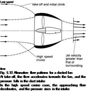
By placing a fan or propeller in a duct or shroud, as in Fig. 6.10, flow patterns can be obtained, that are significantly different from those produced by an unducted propeller or fan. The flow patterns depend on the relationship between the flight speed and the engine thrust. Figure 6.10 shows two sets of patterns, one corresponding to the low speed high-power take-off condition, and the other to the high speed cruise case. In this figure, the broken lines represent streamlines which divide the flow that goes round the outside of the duct, from that which flows through it. Again, in three dimensions, these would correspond to stream-tubes, which may be termed dividing stream-tubes.

To explain how the duct or shroud works, we shall look first, at a subsonic flow of air through a converging streamlined duct with no fan to assist it, as illustrated in Figure 6.11. Since no energy is being added, the device cannot produce a thrust, so the jet of air at C (where the pressure is at the free-stream value) cannot be moving faster than the free stream at A.

Подпись: Low speed flow Fig. 6.10 Alternative flow patterns for a ducted fan At take-off, the flow accelerates towards the fan, and the pressure falls in the duct intake In the high speed cruise case, the approaching flow decelerates, and the pressure rises in the intake

The dividing stream-tube diameter at A must, therefore, be no larger than at C, since the same amount of air is passing at about the same speed at both A

The ducted fan

Fig. 6.11 Flow through a streamlined duct

If no energy is added, then the flow speed at C cannot be greater than at A, since the pressure is atmospheric at both positions. In the duct at B, the flow speed is lower, and the pressure is higher than the surrounding atmosphere

and C. As the flow enters the duct at B, however, the area is larger, so the speed must be lower there. If the speed falls, then the Bernoulli relationship tells us that the pressure will be higher.

A duct can, therefore, provide a means of reducing the air speed and increas­ing its pressure locally. If we place a fan in the duct, then the addition of energy to the flow can create a jet, and the streamline pattern can be as shown in Fig. 6.12. This is similar to the cruise case shown in Fig. 6.10.

As shown, there is still a reduction in speed, and an accompanying increase in pressure as the flow enters the duct. This is a very useful feature if the aircraft is flying at a high subsonic Mach number, because the air now enters the fan at a lower Mach number. The Mach number is lowered further, by the fact that the rise in pressure is accompanied by a rise in temperature, so that the local speed of sound is also increased.

In Fig. 6.12 we have shown the surrounding stream-tube for an unducted propeller, having the same diameter as the ducted fan, and producing the same amount of thrust. A fan operated in this way is less efficient than a free pro­peller of the same diameter, since the fan draws its air from a smaller area of the free stream, as shown in Fig. 6.12. The mass of air used per second, and the resulting (Froude) efficiency are, therefore, both smaller for the fan. The price is, however, worth paying, as the fan may be used at flight Mach numbers where conventional propellers suffer excessive losses due to compressibility effects.

It should be noted, that for high speed turbo-fan (fan-jet) propulsion, it is normal for the outer part of the blade to run with supersonic relative flow between the blade and the air, but with subsonic relative flow for the inner

The ducted fanPressure greater than surrounding atmospheric

Подпись: Dividing stream-tubeПодпись: for ducted fanSurrounding stream-tube

for an unducted propeller producing

the same amount of thrust

Fig. 6.12 Ducted fan at high speed

As with the simple unassisted flow through a duct, the flow slows down as it enters the duct, and the pressure rises. The surrounding stream-tube for a propeller of the same diameter producing the same amount of thrust, is shown by dashed lines part. We shall deal with the linking of such ducted fans to gas-turbine engines to provide turbo-fan propulsion later.

Aircraft size

Any observer of commercial aircraft over the past few decades cannot fail to have noticed that the size of airliners has dramatically increased, particularly for the longer ranges, hence the A380, Fig. 13.12. The reason for this is quite simple. Apart from the wings, contributions to the overall drag of the aircraft come from a variety of other sources, including the fuselage. For similar fusel­ages the capacity increases as the cube of the diameter while the surface area only increases as the square. Since the drag is dependent on the surface area this means a reduction in the drag contribution per passenger, and a consequent improvement in the economy of operation.

Of course other considerations work to restrict the size. In order to provide an attractive and useful service, the airline must operate a reasonably frequent service over a given route. If this results in the aircraft having to operate with a substantial number of seats empty this clearly undoes any improvement due to the increase in size.

Other factors include the provision of passenger handling facilities at air­ports which are able to deal with a very large number of passengers joining or leaving a large aircraft. Any reader who has had the unfortunate experience of being a passenger on a diverted jumbo jet will have first-hand experience of the chaos which can result at the unsuspecting passenger terminal of the receiving airport.

Getting the load distribution right

The loading distribution for a swept wing of constant section and geometric incidence along the span (Fig. 9.14) shows that, as well as an increase in local load towards the tips, there is a decrease in the centre section. The region of high load means low pressures on the top of the wing surface. This in turn means that the local velocity, and hence Mach number, will also be high in this region. Thus the tip region will be the first to encounter the transonic drag rise and stall, while the rest of the wing, particularly the centre section, is com­paratively lightly loaded.

If this state of affairs is not corrected, the wing will not be particularly efficient. It may be thought that this would not create too much difficulty because the Mach number could be pushed up slightly and the reduction in performance near the tip tolerated. However increase of Mach number in the tip region would lead to unacceptable shock-induced flow separation resulting in buffet and even stall.

We saw in Chapter 2 that the load variation across the span could be altered by modifying the wing planform. This is also true with swept wings. Unfortunately, in order to remove the tip load peaks and boost the load in the centre section an inverse taper would be required. This is clearly not a good idea from the structural point of view. The alternative solution of using twist is

Fig. 9.14 Pressure distribution on a simple swept wing

There are strong low-pressure peaks near the leading edge at the tips

Fig. 9.15 The Republic XF-91 had inverse-tapered wings

the one nearly always adopted. Figure 9.15 shows a rare example of an aircraft with inversely tapered wings.

Typically the wing of a transonic transport will have 5% washout (reduced geometric incidence towards the tip) over the span and employ the more struc­turally acceptable conventional taper.

Unfortunately the use of twist to correct the load distribution can only pro­duce the desired result at a particular design angle of attack. As the speed reduces so the load distribution will tend to revert to the previous undesirable form and leading and trailing-edge flaps must be used to correct further.

Automatic control systems and autopilots

The earliest form of automatic control or autopilot consisted of a device to keep the aircraft flying on a steady heading at constant height. They normally employed a number of mechanical gyroscopes which were used to sense the motion of the aircraft and apply suitable corrective control inputs. These so-called ‘inertial’ systems have been developed to a high level of precision and sophistication, particularly in military aircraft and missiles, and can provide highly accurate guidance and control. Laser-based electronic inertial and GPS sensors have now largely replaced the mechanical gyroscopes.

During the Second World War, guidance and navigation systems using ground-based radio transmissions were developed, primarily for bombing missions, and these were subsequently adapted for civilian applications. Nowadays, an autopilot may be linked to a complex set of navigation systems and instruments, and can be programmed so that the aircraft follows a pre­determined flight pattern, including variations in speed, altitude and direction.

Satellite-based navigation systems can now provide pinpoint positional indica­tion and may eventually replace the older ground-based systems altogether.

As we shall describe in later chapters, automatic control systems can be used to help enhance stability, to improve performance and manoeuvrability, and to help provide safe landing, particularly in poor visibility. A good introduction to avionic systems is given in D. H. Middleton’s book.

Take-off configuration

Since it is clearly an advantage for an aircraft to be able to operate from the minimum possible length of runway there is a strong pressure on the designer to have as low a stalling speed as possible. This requirement is not compatible with the demand for low drag at cruise and the section is modified for take-off by means of leading-edge slats, trailing-edge flaps and other devices already mentioned. For light aircraft the runway requirements are generally not too great and a simple trailing-edge flap deflection, or indeed no modification at all, may be sufficient. For high performance aircraft or transonic transport aircraft, however, more sophisticated high lift devices are required (Chapter 3). In par­ticular some sort of leading-edge slat or droop will normally be employed. Figure 13.2 shows a typical take-off configuration.

High speed helicopters and convertiplanes

One way to get around the problems of high speed flight in helicopters is to equip them with wings and a conventional propulsion system in addition to the rotor. In high speed flight, the wings take over the provision of lift, and the rotor blades can rotate slowly, or even be folded back.

High speed helicopters and convertiplanesThe co-axial contra-rotating helicopter rotor mentioned above also has an advantage in high speed flight, as it can be arranged that the lift is provided only by the advancing pairs of blades (one on each side of the aircraft) which, therefore, do not need to move much faster than the aircraft.

High speed helicopters and convertiplanes

Fig. 1.29 High speed helicopter

The BERP tips helped to take this modified Lynx to a record-breaking 249.1 mph. By the standards of conventional aircraft this is quite slow

(Photo courtesy of Westland Helicopters Ltd)


Подпись: HIGH SPEED HELICOPTERS AND CONVERTIPLANES

ы

Ы


High speed helicopters and convertiplanes

Fig. 1.30 The Boeing-Bell V-22 Osprey convertiplane

The convertiplane combines the VTOL capability of the helicopter, with the economy and speed of a turbo-prop, but the cost and complexity is considerable (Photo courtesy of Bell Helicopter Textron Inc.)

Another solution is a convertiplane, such as the Bell V-22 Osprey illustrated in Fig. 1.30. In this design, the rotor blades are tilted forwards in high speed flight to become large-diameter propellers. As with the other solutions described above, this apparently simple arrangement is not without its problems, and it took decades of development and several different experimental aircraft before a production type was finally built.

Leading-edge devices

In addition to trailing-edge flaps, a variety of leading-edge devices may be used. The simplest of these is the leading-edge flap, which is used to increase the cam­ber of the leading edge. Leading-edge flaps can take the form of a simple hinged section, as in Fig. 3.13(f), but a more effective arrangement is to slide or fold the flap forward to increase the wing area, as shown in Fig. 3.13(g). Leading – edge flaps may be seen deployed in Fig. 3.15.

We can utilise the principle of boundary layer control by introducing a gap or slot in the leading edge, as in Fig. 3.13(g). Like the slotted flap, the air gap allows a fresh boundary layer to develop behind the slot, which helps to prevent leading-edge separation. The slot may be formed by moving the lead­ing edge forward, in which case, the articulated portion is known as a slat. Leading-edge devices are particularly useful for thin aerofoil sections where leading-edge separation is likely to occur.

Simple unflapped aerofoils normally generate a maximum lift coefficient value of less than 2, but as long ago as 1921, Sir Frederick Handley Page and

Leading-edge devices

Fig. 3.15 Leading-edge flap deployed on a Tornado

G. V. Lachmann managed to achieve lift coefficient values as high as 3.9 using multiple element aerofoils. The patented Handley Page leading-edge slat was a feature of several aircraft built by the Handley Page company.

There are many variations in the mechanisms used for leading-edge devices. In some cases, the slat is held in by spring tension, and extends automatically at high angle of attack by the action of leading-edge suction.

Turning the flow the other way – the expansion

We have now seen how the flow can be turned by a shock wave resulting in an increase in pressure, density and temperature of the air as the flow is almost instantaneously slowed by the shock. If we turn the air in the opposite direction

Turning the flow the other way - the expansion

Fig. 5.16 Expansion

The flow accelerates around the corner through an expansion fan. Pressure decreases so pressure gradient is favourable for the boundary layer, which remains attached

(Fig. 5.16) we find that the pressure decreases as do both density and temper­ature, while the speed increases. If we look at the process in greater detail we see that the process of expansion is not sudden as in the case of the shock wave compression, but takes place over a well defined area.

It is interesting to observe that at supersonic speed the flow is much better able to negotiate this type of corner than it is at subsonic speed where bound­ary layer separation would almost certainly result (Chapter 3). In fact the degree of turn that can be achieved by a supersonic stream is quite surprising.

At first sight it seems strange that the faster flow is better adapted to making sudden changes in direction, but the clue to why this should be so has already been given in Chapter 3. The problem in subsonic flow is that the boundary layer separates and one of the primary causes of this is an increasing pressure in the direction of the flow; an adverse pressure gradient. If we now look at the change in pressure around the corner for the subsonic case we see that there is, indeed, an adverse pressure present. In supersonic flow, however, the pressure gradient around the corner is in the favourable sense and acts to prevent boundary layer separation (Fig. 5.16).

This difference in the ability of subsonic and supersonic flows to turn cor­ners is not just of academic interest. The supersonic aerofoil section shown in Fig. 5.17 is perfectly adequate for use at its design speed, but will have a very

Turning the flow the other way - the expansion

Fig. 5.17 Supersonic aerofoil section (double wedge)

This section has good supersonic but poor subsonic performance

poor subsonic performance. As we shall see in Chapter 8, this makes the designer’s life much more difficult since, with the exception of some missiles, most aircraft have to land and take off and must therefore be capable of satis­factory operation at both subsonic and supersonic speed.

By-pass or turbo-fan engines

For a given amount of thrust, the Froude efficiency can be improved by increas­ing the mass flow rate of air, while reducing the jet speed. This can be achieved by increasing the size of the low pressure compressor stage, and by-passing some of the compressed air around the outside of the combustion chamber and turbine, as illustrated in Fig. 6.23. As in this illustration, separate spools are normally used for the low pressure by-pass and high pressure core stages. The hot and cold jets are arranged to have about the same velocity at exit.

The low pressure by-pass stages are effectively ducted fans, and by-pass jet engines are described as turbo-fans. In Britain, the term was originally only applied to high by-pass ratio engines (described below).