Category Airplane Stability and Control, Second Edition

The U. S. Military Services Follow NACA’s Lead

Following NACA’s lead, both the U. S. Air Force and the U. S. Navy Bureau of Aeronautics issued flying qualities specifications for their airplanes. Indeed, after the war, the allies discovered that the Germans had established military flying qualities re­quirements at about the same time. In April 1945 the U. S. Air Force and Navy coor­dinated their requirements, recognizing that some manufacturers supplied airplanes to both services. The coordinated Air Force specification got the number R-1815-A; the corresponding Navy document was SR-119A. In 1948 the final step was taken and the services put out a joint military flying qualities specification, MIL-F-8785. This docu­ment went through many subsequent revisions, the most significant of which was the 1969 MIL-F-8785B(ASG).

The main difference between Gilruth’s NACA requirements and the military versions was in the detailed distinctions made by the military among different types of aircraft. For example, in the military version, maneuvering control force, the so-called stick force per g, was generalized to apply to airplanes with any design limit load factor. NACA had recognized only two force levels, for small airplanes with stick controls and for large ones with wheel controls. Special requirements were given in the joint specification for aircraft meant to fly from naval aircraft carriers. MIL-F-8785 and its revisions were incorporated into the procurement specifications of almost all military aircraft after 1948.

The transformation of one particular flying qualities requirement from the original NACA or Gilruth version through successive military specifications can be traced (Westbrook and McRuer, 1959). This requirement is for the longitudinal short-period oscillation. The longitudinal short period is a relatively rapid oscillation of angle of attack and pitch attitude at relatively constant airspeed. The original NACA requirement applies to the stick-free case only, as follows:

When elevator control is deflected and released quickly, the subsequent variation of normal acceleration and elevator angle should have completely disappeared after one cycle.

Gilruth (1943) goes on to give reasons for this requirement, as follows:

The requirement specifies the degree of damping required of the short-period oscillation with controls free. A high degree of damping is required because of the short period of the motion. With airplanes having less damping than that specified, the oscillation is excited by gusts, thereby accentuating their effect and producing unsatisfactory rough-air characteristics. The ratio of control friction to air forces is such that damping is generally reduced at high speeds. When the oscillation appears at high speeds as in dives and dive pull-outs, it is, of course, very objectionable because of the accelerations involved.

The first U. S. Air Force specification, C-1815, relaxed the NACA requirement, allowing complete damping in two cycles instead of one. This was done because opinions collected from Air Force pilots and engineers were that the response with the stick fixed was always satisfactory, and so the short-period oscillation was of no importance in design. However, by the time of a 1945 revised specification, R-1815-A, further experience led back to the original NACA requirement of complete damping for the stick-free case in one cycle. A refinement to an analytically more correct form, one better suited for design and flight testing, was made in the next revision, R-1815-B. This is damping to 1/10 amplitude in one cycle, corresponding to a dimensionless damping ratio of 0.367.

Modern design trends, especially higher operating altitudes and wing loadings, decreased the damping in the stick-fixed case, while with irreversible controls the stick-free case essentially disappeared. When the initial stick-fixed damping requirements were set, in MIL – F-8785, the level was set at a damping ratio of 0.110, or damping to a half-amplitude in one cycle. This relatively low damping requirement is based on NACA experience with research airplanes, whose pilots seem agreeable to low damping levels. As service experience was gained with high-altitude, dense airplanes the trend was reversed and damping requirements were increased again.

This uncertainty in the desirable level of longitudinal short-period damping was typical of what led to ambitious, reasonably well-funded Air Force and Navy research programs to rationalize the flying qualities data base. In the United States, flying qualities flight and ground simulator testing went on all over the country, especially at the NACA laboratories, the Cornell Aeronautical Laboratory, Systems Technology, Inc., NATC Patuxent River, Wright Field, and at Princeton University. British, German, Dutch, and French laboratories also became active in flying qualities research at this time.

Under U. S. Air Force sponsorship, the Cornell Aeronautical Laboratory used a variable – stability jet fighter to make a systematic attack on the longitudinal short-period damping question. Robert P. Harper and Charles R. Chalk ran experiments with variations in short – period damping and frequency at constant levels of stick force and displacement per unit normal acceleration. They found a “bull’s-eye” of good damping and natural frequency combinations, surrounded by regions of acceptable to poor performance.

This and similar efforts went into successive revisions of MIL-F-8785, reaching at last the “C” revision ofNovember 1980. All along, the specification writers were guided by peer reviews and conferences involving specification users in the industry. At one point, the U. S. Navy Bureau of Aeronautics requested Systems Technology, Inc. to search for weaknesses in the specification. The resultant report (Stapleford, 1970) was issued with the attention­getting title, “Outsmarting MIL-F-8785(ASG)” Good summaries of the revision work may be found in Chalk (1969) and Ashkenas (1973).

Corded Controls

Corded controls, apparently invented in Britain, are thin cylinders, such as actual cord, fastened to control surfaces just ahead of the trailing edge. They are used on one

Corded Controls

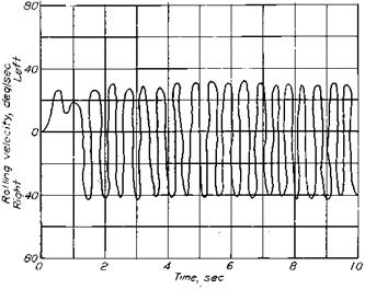
Figure 5.9 Overbalance at small deflections, the downside of control surface bevel. Beveled ailerons with an excessive angle of 32 degrees go through a limit cycle oscillation on an XP-51 airplane. The oscillation is poorly traced from an original. (From Toll, NACA Rept. 868, 1947)

or both sides of a control surface. Corded controls are the inverse of beveled controls. Bevels on the control surface side that projects into the wind produce relative negative pressures near the bevel that balance the control aerodynamically, reducing operating force. On the other hand, cords on the control surface side that projects into the wind create local positive pressures on the surface just ahead of the cord. This increases control operating force.

Cords on both sides of a control surface are used to eliminate aerodynamic overbal­ance. On one side they act as a fixed trim tab. Very light control forces have been achieved by cut and try by starting with aerodynamically overbalanced surfaces, caused by delib­erately oversized overhang balances. Quite long cords correct the overbalance, providing stable control forces. In the cut and try process the cords are trimmed back in increments until the forces have been lightened to the pilot’s or designer’s satisfaction. Adjustable projections normal to the trailing edge, called Gurney flaps, act as one-sided cord trim tabs.

Grumman XF10F Jaguar

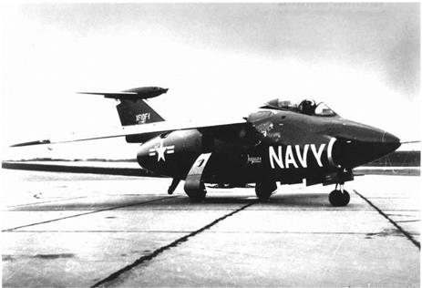
The variable-sweep XF10F Jaguar was Grumman’s attempt to avoid fully powered pitch controls during the jet’s awkward age. The Jaguar’s horizontal tail was on a large streamlined pod that pivoted in pitch on top of the vertical tail (Figure 7.3). This pivoted assembly was in effect a separate canard airplane, trimmed in pitch by a direct connection between the pilot’s stick and the canard.

The trim lift coefficient attained by the pivoted canard tail assembly was of course the tail lift coefficient for the XF10F as a whole. This ingenious system amounted to a tab control system, since the canard control surface attached to the pilot’s stick was a relatively small surface with low hinge moments. Yet the tail loads for the XF10F’s stability and control were provided by an all-moving surface that was not subject to control surface effectiveness losses and unpredictable hinge moments at transonic Mach numbers.

In Navy flight tests, the XF10F ran out of nose-up longitudinal control for landing at some loadings, due to insufficient down deflection of the canard. Another serious problem with the canard airplane horizontal tail was a low natural frequency at low airspeeds. This produced a large time lag between pilot stick motion, tail, then airplane, response. Pilots complained that at low airspeeds they had no idea of the tail’s incidence angle.

The Navy canceled production plans for the variable-sweep XF10F in 1953. The airplane never received the engine it was supposed to have, leaving it with poor performance. Also, the advent of slanted deck carriers and steam catapults allowed fixed-sweep airplanes to be

Grumman XF10F Jaguar

Figure 7.3 The Grumman XF10F-1 Jaguar, an attempt to avoid powered pitch controls. A freely pivoted canard-controlled body and wing is mounted on top of the vertical tail. The pilot’s stick moves the canard, which controls the angle of attack of the pivoted body. (From National Air and Space Museum)

operated from carriers. The XF10F’s ingenious canard airplane horizontal tail design has not been used on later airplanes.

Control Sensitivity and Overshoots in Rapid Pullups

When powerful, light longitudinal controls became available for tactical airplanes, the problems of oversensitivity, sluggishness, normal acceleration overshoots, and pilot – induced oscillations appeared. Airplane-pilot coupling, also called pilot-induced oscilla­tions, is properly dealt with as the combination of the dynamics of human pilots with that of their airplanes (see Chapter 21). However, oversensitivity, sluggishness, and overshoots may be understood in simpler terms, that of the airplane alone, without specifically in­volving pilot dynamics. A fundamental indicator of airplane-alone pitch response is the pitch rate transfer function for elevator or stabilizer control inputs (Figure 10.2). Under the usual constant-airspeed assumption, this function has a second-order denominator and a first-order numerator. Although a pure delay may be added, only three parameters are involved: the frequency and damping ratio of the second-order term and the time constant of the first-order term. A number of criteria on oversensitivity, sluggishness, and overshoots deal with this airplane-alone transfer function.

10.3.1 Equivalent Systems Methods

Equivalent systems or low-order approaches refer to fitting an airplane-alone transfer function to the complex dynamics of actual airplane and flight control systems. Hodgkinson, La Manna, and Hyde (1976) are generally referenced as the origin of the

Control Sensitivity and Overshoots in Rapid Pullups Control Sensitivity and Overshoots in Rapid Pullups

A mechanism or complete system with input x and output y defined by the differential equation

can be represented by the transfer function in the Laplace variable s:

Y(s) _ K(sn + a1sn 1 + ••• + an-1s + an)

X(s) = sm+n + b1sm+n-1 + ••• + bm+n_ 1s + bm+n ^

An example is the pitch rate transfer function for elevator or stabilizer inputs, with the airspeed degree of freedom suppressed:

q(s) _ (Ms + ZsMw)s + ZsMw — MsZw

S(s) = s2 —(UoMw + Zw + Mq)s + MqZw — UoMw •

In these equations, a, b = constants K = gain

Ms, Zw, etc. = control and stability derivatives q = pitching velocity s = Laplace variable Uo = forward speed S = elevator or stabilizer deflection.

Figure 10.2 The transferfunction concept. (Adapted from AircraftDynamics andAutomatic Control, by McRuer, Ashkenas, and Graham, Princeton U. Press, 1973)

equivalent systems method. The McRuer, Ashkenas, and Graham approximate factors, with time delay added from variable stability NT-33 tests carried out by Dante DiFranco, were used to match frequency responses of the Neal-Smith data set.

Transfer function criteria, for the airplane alone or the equivalent system, have the authority of a great deal of analysis, simulator, and flight research. Excellent reviews of this field are given by Gibson (1995) and by Hoh and Mitchell (1996). While the original work on transfer-function-based criteria was concerned with tactical airplanes, these criteria were used as well in the flight control designs of modern transport airplanes such as the Boeing 777 (Ward, 1996) and the Airbus series, starting with the A320.

Commercial and Kit-Built Ultralight Airplanes

There are three classes of commercial and kit-built ultralight airplanes, each with interesting stability and control characteristics. Using the terminology of the influential Jane ’sAll the World’s Aircraft, the most simple is the classical modern hang glider, developed from the Rogallo wing (Rogallo et al., 1960). Control is obtained by shifting body weight, as in the nineteenth-century Lilienthal hang gliders. The next level of sophistication is called a parawing. It is a powered ram air parachute. Finally, there is the broad category of microlights. These airplanes range from powered hang gliders to lightly constructed airplanes of conventional layout. Like the hang glider, microlights use fabric-covered light structures.

The FAA in the United States and the CAA in the United Kingdom have each de­veloped certification provisions for ultralight airplanes, FAR Part 103 (1990) and BCAR Section S-CAP 482, respectively. FAR Part 103 applies to unpowered ultralights weigh­ing less than 155 pounds and powered ultralights weighing less than 254 pounds; powered ultralights have top speeds less than 55 knots and stalling speeds less than 24 knots. Part 103 specifically exempts these ultralights from meeting airworthiness standards. Operating rules only are specified. Other countries use the FAA and CAA standards for their own certifications.

A comprehensive review of hang-glider stability and control is presented by Anderson and Ormiston (1994). Longitudinal trim is provided by reflexed airfoil shapes. Directional stability is generally positive because of wing sweep. Geometric dihedral is adjusted for neutral spiral stability at cruise. A surprising finding is low Dutch roll stability at low angles of attack. This has led to pilot-induced oscillations, augmented by inadvertent swing of the body in response to side accelerations. Hang-glider full-scale tests on an outdoor mobile test rig were conducted at Cranfield University (Cook and Kilkenny, 1987).

The stability and control characteristics of powered hang gliders, called flexwing air­planes by the author, were discussed by Brooks (1998). Turn control of these machines is unconventional, as in the case of the Gossamer Condor. To turn right, the pilot’s weight is moved to the right by exerting force to the left on the control frame base bar. The weight moment and aeroelastic wing flexing (right wing washout) combine to start a right roll. Adverse yaw causes right sideslip. Anhedral, or negative dihedral effect, increases the right rolling moment, accelerating the turn.

Commercial and Kit-Built Ultralight Airplanes

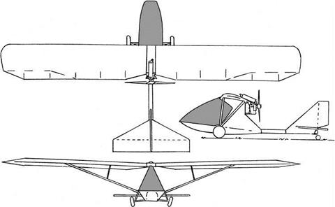
Figure 13.1 Chinook WT-11 ultralight airplane, general arrangement. (From Roderick, 1986)

A brief wind-tunnel test of the fabric-covered wing and tail surfaces of a Chinook WT-11 ultralight airplane (Figure 13.1) conducted in the Canadian NAE 9m by 9m low-speed wind tunnel (Roderick, 1986) showed some unusual characteristics. There was noticeable wing twist at higher dynamic pressures, which decreased wing lift curve slope. With the elevator deflected, the horizontal tail had nonlinear lift curves near its stall. The investigators concluded that a large amplitude pitch down at the stall was a possibility.

Aside from the technical findings of these investigators, experience has shown that inad­vertent stalling is a major cause of ultralight accidents. Operators of ultralights under U. S. FAR Part 103 are not required to pass knowledge or experience tests. However, avoidance of inadvertent stalling during the demanding operations of approach and landing requires careful training.

The F-111 Aardvark, or TFX

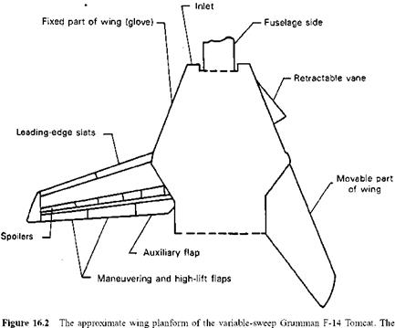
Practical variable sweepback came along just in time for the all-service TFX concept, which later became the Air Force’s F-111 (Figure 16.1). The F-111 uses the

The F-111 Aardvark, or TFX

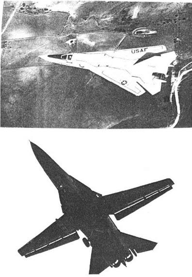
Figure 16.1 The F-111 with wings fully swept at 72.5 degrees and fully unswept at 16 degrees.

(USAF photos)

The F-111 Aardvark, or TFX

retractable glove vane reduces excessive longitudinal stability with the wings fully swept back. (From Loftin, NASA SP 468, 1985)

Alford-Polhamus-Wallis rotation-only mechanism. The wing sweep range is 16 to 72.5 degrees, with normal subsonic cruise at a sweep of 26 degrees. Triply redundant three-axis stability augmentation is used. There are no particular stability and control problems with this machine.

The Elastic Airplane

Aeroelasticity deals with the interactions of aerodynamic and inertial forces and aircraft structural stiffness. Additional significant interactions with aerodynamic heating and automatic control systems give rise to the Germanic-length terms aerothermoe – lasticity and aeroservoelasticity. Aeroelasticity concerns stability and control, dealt with here, but also flutter and structural loads arising from maneuvers and atmospheric turbu­lence. Aeroelasticity affects airplane stability and control in a number of areas. Prediction of aerodynamic data at the design stage (Chapter 6), tactical airplane maneuverability (Chapter 10), the equations of motion (Chapter 18), and stability augmentation (Chapter 20) are all affected.

Aeroelastic effects are considered as distractions by many stability and control engineers, obscure problems that get in the way of the real work at hand. Aeroelastic methods are certainly abstract, involving such arcana as normal modes. How does one fix body axes in a flexible structure? What is its angle of attack? We trace this difficult but important branch of stability and control from the early days of Samuel Langley, the Wright brothers, and Anthony Fokker to the present.

The early days were dominated by isolated occurrences of aeroelastic problems and ad hoc solutions. The advent of large-scale digital computers and finite-element or panel methods for the first time provides, if not a general theory, at least an organized approach to prediction and solution of stability and control aeroelastic problems.

Practical Problems with Digital Systems

When digital stability-augmentation systems first appeared, their most alluring advantage, as compared with analog systems, was their ability to change system gains, shaping networks and even architecture by software changes, instead of requiring time­consuming hardware changes. This is especially attractive in a prototype flight testing program, as may be imagined. However, a drawback to this capability is that the ease of making changes by software modifications encourages a cut and try approach to fixing problems.

The same design freedom that makes for easy changes in a digital stability-augmentation system makes it easy to load the design with overly complex gain schedules and cross-feeds. In a recent classified program, practically all system gains are complex functions of altitude, Mach number, angle of attack, center of gravity, and other measurable parameters, with no real proof that this complexity is needed. One result of complex gain schedules is an inordinate amount of time required for checkout in simulation and flight testing.

On the hardware side, one can be faced with digital flight control systems that incorporate several sampling systems, operating at different rates and not in synchronization. This is the case on the Grumman X-29A digital flight control system. Again, careful simulation and bench testing is needed to be sure that no problems arise from this. Anti-aliasing filters are generally needed on the inputs of analog-to-digital converters, to screen out input frequencies that are multiples of the digital sampling frequency.

Changing Military Missions and Flying Qualities Requirements

Flying qualities requirements for general aviation and civil transport airplanes are predictable in that these airplanes are almost always used as envisioned by their designers. This is not so for military airplanes. The record is full of cases in which unanticipated uses or missions changed flying qualities requirements. Four examples follow.

A4D-1 Skyhawk. The A4D-1, later the A-4, was designed around one large atomic bomb, which was to be carried on the centerline. A really small airplane, the A4D-1 sits high on its landing gear to make room for its A-bomb. The airplane was designed to be carrier-based. However, the A4D-1 was used instead mainly as a U. S. Marine close-support airplane, carrying conventional weapons and operating from single-runway airstrips, often in crosswinds. The vestigial high landing gear meant that crosswinds created large rolling moments about the point of contact of the downwind main tire and the ground. In simpler terms, side winds tried to roll the airplane over while it was landing or taking off. Originally, pilots reported that it was impossible to hold the upwind wing down in crosswinds, even with full ailerons. Upper surface wing spoilers had to be added to the airplane to augment aileron control on the ground.

B-47 Stratojet. This airplane started life as a high-altitude horizontal bomber. Its very flexible wings were adequate for that mission, but not for its later low-altitude penetration and loft bombing missions. Loft bombing requires pullups and rolls at high speed and low altitude. In aileron reversal ailerons act as tabs, applying torsional moments to twist a wing in the direction to produce rolling moments that overpower the rolling moments of the aileron itself. This phenomenon limited the B-47’s allowable airspeed at low altitudes.

F-4 Phantom. The F-4 was developed originally for the U. S. Navy as a long-range attack airplane, then as a missile-carrying interceptor. A second crew member was added for the latter role, to serve as a radar operator. Good high angle of attack stability and control were not required for these missions, but then the U. S. Air Force pressed the F-4 into service in Vietnam as an air superiority fighter. Belatedly, leading-edge slats were added for better high angle of attack stability and control.

NC-130B Hercules. This was a prototype C-130 STOL version, fitted with boundary layer control. The airplane’s external wing tanks were replaced by Allison YJ56-A-6 turbo­jets to supply bleed air for the boundary layer control system. At the reduced operating air­speeds made possible by boundary layer control the C-130’s unaugmented lateral-directional dynamics, or Dutch roll oscillations, were degraded to unacceptable levels.

“Systems engineering” as a discipline was a popular catchphrase in the 1950s. Airplanes and all their accessories and logistics were to be developed to work together as integrated systems, for very specific missions. The well-known designer of naval airplanes Edward H. Heinemann was not impressed. Heinemann’s rebuttal to systems engineering was, “If I build a good airplane, the Navy will find a use for it.” Heinemann’s reaction to systems engineering seems justified by the four cases cited above, in which flying qualities requirements for the airplanes changed well after the designs had been fixed.

Hydraulic Control Boost

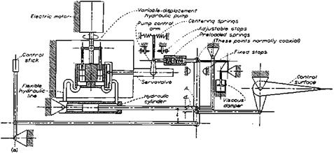
Control boost by hydraulic power refers to the arrangement that divides aerody­namic hinge moment in some proportion between the pilot and a hydraulic cylinder. A schematic for an NACA experimental boosted elevator for the Boeing B-29 airplane shows the simple manner in which control force is divided between the pilot and the hydraulic boost mechanism (Figure 5.16). Boosted controls were historically the first hydraulic power assistance application.

Hydraulic Control Boost

Figure 5.16 A very early hydraulic-boost control, installed by NACA for test on a Boeing B-29 elevator. Boost ratio l/d is varied by adjusting the location of point A. (From Mathews, Talmage, and Whitten, NACA Rept. 1076, 1952)

By retaining some aerodynamic hinge moments for the pilot to work against two things are accomplished. First, the control feel of an unaugmented airplane is still there. The pilot can feel in the normal way the effects of high airspeeds and any buffet forces. Second, no artificial feel systems are needed, avoiding the weight and complexity of another flight subsystem. Hydraulic power boost came into the picture only at the very end of World War II, on the late version Lockheed P-38J Lightning, and only on that airplane’s ailerons. After that, hydraulic power boost was the favored control system arrangement for large and fast airplanes, such as the 70-ton Martin XPB2M-1 Mars flying boat, the Boeing 307 Stratoliner, and the Lockheed Constellation series transports, until irreversible power controls took their place.

5.13 Early Hydraulic Boost Problems

Early hydraulic boosted controls were notoriously unreliable, prone to leakage and outright failures. Among other innovative systems at the time, the Douglas DC-4E prototype airplane had hydraulic power boost. Experience with that system was bad enough to encourage Douglas engineers to face up to pure aerodynamic balance and linked tabs for the production versions of the airplane, the DC-4 or C-54 Skymaster.

A similar sequence took place at the Curtiss-Wright plant in St. Louis, where the Curtiss C-46 Commando was designed. At a gross weight of45,000 pounds, the C-46 exceeded O. R. Dunn’s rule of thumb of30,000 pounds for the maximum weight of a transport with leading – edge aerodynamic balance only. Thus, the CW-20, a C-46 prototype, was fitted initially with hydraulic boost having a 3:1 ratio, like those on the Douglas DC-4E Skymaster prototype and the Lockheed Constellation. However, maintenance and outright failure problems on the C-46’s hydraulic boost were so severe that the Air Materiel Command decreed that the airplane be redesigned to have aerodynamically balanced control surfaces. The previous successful use of aerodynamic balance on the 62,000-pound gross weight Douglas C-54 motivated the Air Corps decree. This was the start of the “C-46 Boost Elimination Program,” which kept one of this book’s authors (Larrabee) busy during World War II.

Another airplane with early hydraulically boosted controls was the Boeing 307 Strato- liner. Hydraulic servos were installed on both elevator and rudder controls. Partial jamming of an elevator servo occurred on a TWA Stratoliner. This was traced to deformation of the groove into which the piston’s O ring was seated. The airplane was landed safely.