Category An Introduction to THE THEORY OF. AEROELASTICITY

MATRICES

We have emphasized above that the simplest formulation of aeroelastic problems usually results in integral equations. The exact solution of such equations is difficult to obtain except in special cases. In general, how­ever, it is permissible to approximate the integral equation by a matrix equation and to obtain the solution by numerical methods. In the present section the meaning of matrices will be explained. Its connection with the finite-differences approximation will be examined in the next section. Practical examples are given in the next chapter.

A table of m X n numbers arranged in a rectangular array of m rows and n columns is called a matrix with m rows and n columns, or a matrix of order m x n. If a(j is the element in the /’th row and yth column, then the matrix can be written down in the following pictorial form:

Подпись: “In“11 “12

We shall denote a matrix either by a single symbol in boldface type such as A, or by a symbol (a{j), the first subscript referring to the row and the second to the column. A square matrix of order n X n is a particular case. So is a single-column matrix of m rows (order m x 1) or a single­row matrix of n columns (order 1 x n). A special square matrix denoted by 0, called a zero matrix, is a square matrix, all of whose elements are zero. Another special square matrix denoted by 1, called a unit matrix, is the following:

1 = (»«)

where
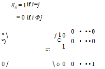
Подпись:These are, respectively,

/0 0

/ 0 0 • • •

………………

o 0

Two matrices are equal when the corresponding elements of each are equal. The addition, subtraction, multiplication, and division of matrices are defined as follows:

Addition. The sum of two matrices A and В is written as A + В and stands for the matrix with elements a(j + b(j.

Subtraction. The matrix — A is defined as the matrix with elements — a{j, and A — В is defined as the matrix with elements atj — btj. For addition and subtraction to be significant, the matrices must have the same number of rows and the same number of columns.

It is clear that the associative law

(A + В) + С = A + (В + C) (1)

and the commutative law

A + В = В + A (2)

both hold for addition of matrices.

Multiplication. The product of the matrices A = (ai}), В = (b(j), written as AB, is a matrix C with elements cu given by

t’H ^ufuj ацЬц ~f~ ЯфЬ^ ~f~ – f – Uinbni

The summation convention (Chapter 1) is used in Eq. 3. In order that the product AB of two matrices be well defined, the number of rows in the matrix В must be precisely the number of columns in the matrix A.

The product is then a matrix, with as many rows as A and as many columns as B..

The commutative law of multiplication does not necessarily hold even if A and В are square. For BA must be defined as the matrix whose elements are bikakj, and this will be equal to aikbkj only in special cases; in general,

AB Ф BA (4)

Pairs of matrices that satisfy AB = BA are said to commute-, those that satisfy AB = — BA to anticommute.

The associative law

(AB)C = A(BC) (5)

and the distributive law

A(B + C) = AB + AC (6)

hold, provided the order is maintained and the operations are significant. Consequently, the products in Eq. 5 can be written without parentheses as ABC, since the position of the parentheses is irrelevant. It follows that all positive powers of a given matrix commute; for A2 A = AA2, and AmA" = A"Am (m, n positive integers) follows by induction.

The unit matrix 1 has the interesting property that it commutes with all square matrices of the same order. In fact,

A1 = 1A = A (7)

The product of two matrices may be a zero matrix without either factor being zero. As an example,

A = (1, 1, 0), В = 10 V AB = (1)(0) + (1)(0) + (0)(1) = 0

The transposed matrix of a matrix A is the matrix formed from A by interchanging its rows and columns. We shall denote it by A’ and its elements by a’ij. Then

a’a = % (8)

Since

(AB)y = aikbkj — a kib jk = b jka ki = (B A (9)

it follows that the transposed matrix of the product AB, denoted by (AB)’, is equal to the product B’A’.

Symmetry Properties. A matrix is said to be symmetrical if it is unaltered by interchanging rows and columns; i. e.,

It is antisymmetrica/ or skew-symmetrical if the sign is changed when rows and columns are interchanged; i. e.,

ai}=~aH or A=-A’ (11)

A diagonal matrix is one all of whose elements are zero except those in the leading diagonal; i. e., au, a22, ■ ■ •, a„„. All pairs of diagonal matrices of the same order commute.

Inverse of a Matrix and the Solution of Linear Equations. The inverse aor reciprocal, of a real number a is well defined if a A 0. Analog­ously, if A is a square matrix of order n and if the determinant аі} Ф 0, then there exists a unique matrix, written as A-1 in analogy to the inverse of a number, with the properties

AA-1 = 1, A-1A = 1 (12)

The matrix A-1, if it exists, is called the inverse matrix of A. The necessary and sufficient condition that a matrix A = (%) has an inverse is that the associated determinant aiS Ф 0. The determinant au is formed by the elements of the square matrix A, and is usually referred to as the determinant of the matrix A. If au vanishes, A has no reciprocal and is said to be singular.

The practical calculation of the inverse of a matrix can be shortened by properly arranging the scheme of computation. The method of Grout[11] is the best known.

We can now define division of matrices as follows: Division by a non­singular matrix is defined as multiplication by its reciprocal, but the quotient depends on the order of the factors as with a product. In general, A_1B is not equal to BA-1.

Since

ABB_1A~3 = АЇА-1 = 1 (13)

it follows that B_3A~3 is the reciprocal of AB, that is (AB)-i. Hence, in forming the reciprocal of a product, the order of the factors must be inverted.

The inverse of a matrix has a simple application to the solution of n nonhomogeneous linear algebraic equations in n unknowns xlt x2, ■ ■ •, xn.

A set of linear equations

may be written in the abbreviated form

ацх1 = b( (15)

where і and j run from 1 to n. If we think of (xt) as a matrix with a single column, Eq. 15 may be written as

AX == В (16)

where В is also a matrix with a single column. If we assume that the determinant of the matrix A is not zero, the inverse matrix A-1 will exist, and we shall have by matrix multiplication

A-J(AX) = А-ЧВ

Since A-1 A = 1 and IX — X, we obtain the solution of Eq. 16:

X = А-ЧВ (17)

Multiplication of Matrices by Numbers. If A = (a{j) is a matrix, not necessarily a square matrix, and c is a number, real or complex, then cA denotes the matrix (caa). This operation of multiplication by numbers enables us to consider matrix polynomials of the type

c0A” + сг A"-1 – f • • • + cn„jA + c„l

where c0, cu • • c„ are numbers, A is a square matrix, and 1 is the unit matrix of the same order as A.

Characteristic Equation of a Matrix and the Cayley-Hamilton Theorem. If A = (fly) is a given square matrix of order n, one can form the matrix M – A, which is called the characteristic matrix of A. The determinant of this matrix, considered as a function of X, is a polynomial of degree n in X, and is called the characteristic function of A. More explicitly, let f{X) = |A1 — A| where |A1 — A| denotes the determinant of A1 — A, then f(X) has the form f(X) = Xn + fljA”-1 + • • • + ап_гХ + an. Since an = /(0), we see that a„ == I — A|. The algebraic equation of degree n for X

js the characteristic equation of the matrix A, and the roots of the equation are the characteristic roots of A..*

We shall quote the famous Cayley-Hamilton theorem without proof: Let

./'(A) — A“ + <ZiAn-1 + • ■ ‘ + an-l^ + an

be the characteristic function of a matrix A, and let 1 and 0 be the unit matrix and zero matrix, respectively, with an order equal to that of A. Then the matrix polynomial equation

X" + fljX"-1 + • • • + an_xX – f – an 1 = 0 (19)

is satisfied by X = A.

MATRICES Подпись: <hn(0 ' ^mn(0 1

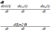
Differentiation and Integration of Matrices Depending on a Numerical Variable. We shall have occasion to differentiate or integrate matrices whose elements depend on a numerical variable. Here we shall give the definitions as follows. Let A(t) be a matrix depending on a numerical variable t so that the elements A(t) are numerical functions of t.

Подпись: dA(t)Подпись: dt doii(t) da12(t) daln(t) dt dt dt d@m2 (0 dt dt dt Then the derivative of A(t), written as —-—, is

dA{t)

dt

Similarly, we define the integral of A(t) by

THE METHOD OF SUCCESSIVE APPROXIMATION

From a mathematical point of view, the method of successive approx­imation possesses a number of advantages. It is best to illustrate it by an example.

Consider again the rectangular wing, for which a, e, c, GJ are constants. In this example

Подпись: t—-У for

Подпись: (1)G(x, y) =

THE METHOD OF SUCCESSIVE APPROXIMATION

{s => У ^ x ^ 0)

and the fundamental equation 3 of § 3.2 becomes

THE METHOD OF SUCCESSIVE APPROXIMATION(2)

THE METHOD OF SUCCESSIVE APPROXIMATION THE METHOD OF SUCCESSIVE APPROXIMATION

If we introduce the nondimensional parameters

Подпись: where Подпись: 0(£) = A Подпись: (4) (5)

as the spanwise coordinates, Eq. 2 may be written as

Let 0(1)(f) = f be the first approximation (a guess) of the solution 0(g). Putting 0a) into the integrals on the right-hand side of Eq. 4, we obtain the value of the integrals

/(i>(f) = ^ if drj + f rj dyj =i($ – – j j (6)

Since 8a>(£) is not an exact solution, it does not satisfy Eq. 4. But, if 6a)(£) approximates closely enough to the correct solution, Eq. 4 must be approximately satisfied. Equating A/(1)(f) with 8a)(£) at one point, say £ = 1, we obtain the approximate critical value A = 3.

As a second approximation let us take the result given by Eq. 6, multi­plied by a suitable constant, and assume

*,w(f) = j(f-y) (?)

Then the integral on the right-hand side of Eq. 4 becomes

w 2 12 6 60/ ‘

The second approximate solution of A is again obtained by equating the value of A/<2)(f) to 0<2)(f) at £ = 1, which gives A = 2.5.

The exact solution is A = 7t2/4 = 2.46740. The error at this stage is 1.30 per cent too large. If we take 8m(£) = f%(£ — ff3 + and substitute into the right-hand side of Eq. 4 to obtain /(3)(£), we will have

/(3>(£) = *U(f – III3 -Г &£5 – тЫ7)

and

A = 2.4705

The error of A is now only 0.12 per cent too large.

It is quite evident how to proceed further. We substitute 8(n>(£) into the right-hand side of Eq. 4, and evaluate the integral. Let the result be written as I{n>(£). If Iw(£)/8(n)(£) tends to a constant in the whole range 0 < £ < 1, then 0ln)(£) is an approximate solution and A = 0(я,(1)//(п,(1).

In order to compare the degree of approximation, it is convenient to normalize all 0<n)(f) in such a way that they are equal at a reference

section. In the above example, we have normalized 6(n)(f) so that

Є<п>(1) = 1.

/ 77-

Подпись: • 77 г- ,m2{ Подпись: 7! Подпись: f7 + - Подпись: ■]
THE METHOD OF SUCCESSIVE APPROXIMATION THE METHOD OF SUCCESSIVE APPROXIMATION

Note that, according to § 3.2, the exact solution is/(£) = sin – f. By series expansion,

which may be compared with our successive approximations 0(1)(f), 0<2>(f), 0(S>(£), etc.

The process is actually a repeated integration. It is iterative. So the method of successive approximation is also called the method of iteration.

An integral equation of the form Eq. 3 of § 3.2 is known as a Fredholm integral equation of the second kind. Since the influence function is symmetric, G(x, y) = G(y, x), the method of iteration will converge to the correct eigenfunction corresponding to the smallest (in absolute value) eigenvalue.

The integration process can be very difficult in practice. Often a simple numerical solution can be obtained by replacing the integrals by a finite sum and transforming the governing equation into a matrix equation. The process of iteration can then be applied to the matrix equation in exactly the same manner as described above.

SOLUTION BY GENERALIZED COORDINATES

An alternative procedure based on the semirigid assumption is to apply the concept of generalized coordinates. This point of view provides a new ground for refinements in the calculation.

Let us again consider the idealized problem of § 3.2. Assume that the angle of twist along the span is a known function of у with unspecified amplitude. Let us write

%) = 0of(y) (1)

* For a uniform beam, the angle of twist due to a concentrated torque applied at the tip (reference) section varies linearly along the span. So the assumption (Eq. 11) is consistent with the influence coefficients, and with the stiffness constant К given by Eq. 9.

where 60 is an undetermined constant and f(y) is a given function. We shall consider в0 as the generalized displacement of the wing. The strain energy due to torsion is


(2)


The equation of equilibrium may be obtained from Lagrange’s equation


£

dt


dV л

+ w~Q


(3)


where the generalized force Q is to be found as follows: The aerodynamic twisting moment about the elastic axis, per unit span, is, according to the strip assumption,

Ma’ = qc2ae0 = qc2ae60f(y)

By permitting a variation of the amplitude 660, the corresponding virtual work is

Q <50o = f Ma'(y) 6 %) dy = f qc2ae60f(y) 660f(y) dy

Jo Jo

Hence,

Q == ?0O fi2ae f%y) dy (4)


At the critical-divergence speed, the wing is neutrally stable. A disturbed configuration can be maintained without causing any motion. Hence the kinetic energy T vanishes, and Eq. 3 implies


f C2aef2(y) dy

Jo


(5)


Therefore,


SOLUTION BY GENERALIZED COORDINATES

Jo


(6)


Let GJ, c, a, e be constants, and assume f(y) — y/s. Then


Example 1.


s

3


SOLUTION BY GENERALIZED COORDINATESSOLUTION BY GENERALIZED COORDINATESSOLUTION BY GENERALIZED COORDINATES

Hence,


Подпись: Уді3 GJ c^aes1

which agrees with the result in § 3.3.

Example 2. Let GJ, c, a, e be constants, and assume

,, , . -ny

|o/4s)rfs-{*in"f*/ = 5

Подпись: Then Подпись: 4s'2 2 8.s

AV) = sm —

Hence,

n4JJ

which agrees with the exact result. In the present approach, a correct assumption of the semirigid mode yields an exact solution.

The procedure can be generalized as follows: Let

П

%)в і Ш) о)

t = о

SOLUTION BY GENERALIZED COORDINATES

wheref({y) (/ = 0, 1, 2, • • •, n) are known functions, and are generalized coordinates. Then

Qi = ( Ma'(y)f№ dy И = 0, 1,2, • • ■, n)

Jo

At the critical-divergence speed,

(/ = 0, 1, 2, • • •, n) (9)

Equation 9 gives a set of homogeneous linear simultaneous equations in Since the вt are, by assumption, not all zero, the determinant of the coefficients of these equations must vanish. This determinantal equation

involves the dynamic pressure qd{v. Its real positive roots are the critical values.

In calculating the aerodynamic moment Ma’ in Eq. 8, a theory may be selected, such as Prandtl’s lifting-line theory or Weissinger’s theory. If we use the strip assumption, then

П

М: = qdh, c2ae^J), fiiy) (10)

1 = 0

Finally, let us remark that, if the functions f{(y) (i = 0, 1, 2, • • •) are infinite in number and form a complete set,* then in the limit n -> oo an exact solution can be obtained.!

Example. Let GJ, e, c, a be constants across the span, and assume

Подпись: У%) = Яі – + Я2~-2

S. Vs

Подпись: GJ Подпись: + 1ф2)Чг}
SOLUTION BY GENERALIZED COORDINATES SOLUTION BY GENERALIZED COORDINATES
SOLUTION BY GENERALIZED COORDINATES

Then

Подпись: GJ 2s + 26A + 022)

By strip theory,

M; = q*ae (^ + 7**1)

Hence,

0i + —2 02) “ ty — qc^aes f (J70x + drl s / s Jo

= ^aes (I + f)

Similarly,

Q2 = qc2aes

* A set of functions fjy), a < у < b, (i = 0, 1, 2, • • •) is said to be “complete” if an arbitrary function u{y) can be expanded into a generalized “Fourier” series of the

OO

formic,/to). i=o

t If the function fly) in Eq. 1 is regarded as unknown, the equation governing/(2/) can be derived from Eq. 5 by considering the first variation of that equation with respect to f(y). The result is the same as that obtained in § 3.2.

Let


1 = GJ^aec2si

SOLUTION BY GENERALIZED COORDINATES

Then the equations of equilibrium 9 become

SOLUTION BY GENERALIZED COORDINATES

A nontrivial solution exists only if the determinantal equation

is satisfied. The two roots are X = 2.48 and 32.3, corresponding to

2.48 G/ 32.3GJ

—– гт and ———-

The first one is the “fundamental” divergence dynamic pressure. Com­pared with the exact value given by Eq. 17 of § 3.2, the error is 0.6 per cent too large.

DIVERGENCE OF AN IDEALIZED CANTILEVER WING

Consider an idealized unswept cantilever monoplane wing which has a straight elastic axis normal to a fuselage that is fixed in space, as in a

* This shows that, although Eq. 7 gives a finite value of the torsional deflection when the speed of flow exceeds the divergence speed, that equilibrium position is unstable. Note that the equilibrium value of в when q > qaiv is greater than a in magnitude and opposite in sign; i. e., the wing twists to opposite direction of a.

wind-tunnel testing. For such a wing the action of a general distributed load can be considered as produced by a distributed load acting through the elastic axis and a distributed twisting moment about the elastic axis. The former produces pure bending which does not affect the angle of incidence, whereas the latter produces rotation of the sections about the elastic axis.

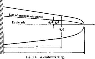
The aerodynamic lift acts through the line of aerodynamic centers. The moment about the aerodynamic centers does not change appreciably with the angle of attack and can be neglected. Let L'(y) be the lift per unit span and ce the eccentricity of the elastic axis from the aerodynamic center (positive when the elastic axis lies behind the latter). Then the aerodynamic moment about the elastic axis is L'(y)c(y)e(y) per unit span.

The equation of divergence for a wing as shown in Fig. 3.3 can now be

DIVERGENCE OF AN IDEALIZED CANTILEVER WING

derived. The fuselage of the airplane is assumed fixed in space. At the critical divergence speed, the aerodynamic moment about the elastic axis just balances the elastic moment due to twisting. For the first approxi­mation, let us make the strip assumption that the aerodynamic lift on a chordwise strip, of width dy, due to a change of angle of attack U(y), is given by

L'(y) dy = q c(y) dy • a 0(y)

where a is the lift-curve slope corrected for aspect ratio.* The aero­dynamic moment about the elastic axis is therefore

M'(y) dy = qa e(y) c%y) 0(y) dy (1)

If G(x, y) represent the influence function for wing rotation at x about the

* To account for the finite span effect, a should be corrected for the aspect ratio, as given by Eq. 15 of § 1.5 et seq.; see also § 4.3. With this correction, the resulting qai is quite accurate. Cf. Miles.3-12

DIVERGENCE OF AN IDEALIZED CANTILEVER WING

elastic axis due to a unit couple at y, then, the wing being in static equi­librium, the total angle of rotation 6(x) at x is

Note that Eq. 3 is satisfied only at the divergence speed, because at other speeds the wing will not be in static equilibrium if it is displaced from an equilibrium configuration, and inertia forces must be considered. This fact is indicated by writing qdlv instead of q in the equation above.

Differentiating Eq. 3 with respect to x and substituting Eq. 5, we obtain

Multiplying both sides of Eq. 6 by GJ(x) and differentiating once, we obtain

Подпись: d_ dx GJ(x) j = – qdiv a e(x) c2(x) d(x) (7)

The boundary conditions for Eq. 7 must correspond with Eq. 4; these are

d(x) = 0 when x = 0

Подпись: (8)dO(x) „ ,

—-— = 0 when x = s dx

Equation 3 or Eqs. 7 and 8 are the fundamental equations for divergence of the idealized wing specified above. The simplification introduced by

choosing the elastic axis as a reference line for measuring the moment and twisting of the wing should be noted. If an arbitrary line is chosen as a reference line, and the aerodynamic action is resolved into a lift force acting through this reference line and a moment about it, the change of angle of incidence of the wing would have to be expressed by two influence functions: one giving the rotation at x due to a unit force at у acting on the reference line, and the other giving the rotation at x due to a unit moment at у about the reference line. The final result is equivalent to the above equations. Therefore, whenever an elastic axis can be defined and is a straight line, its use as a reference line simplifies the derivation. In general, however, for aircraft structures an elastic axis may not be easily defined because of the effect of sweep angle, cutout, or restrained warping; then the use of an arbitrary reference line together with the corresponding influence functions may become imperative. These influence functions may be computed by more advanced structural theory or by experiments.

Note further that, if the wing aspect ratio is small, or if the deformation in the root region of a swept or a delta wing is aerodynamically important, the chordwise sections may not be considered as rigid. Then it is no longer pertinent to speak of the “rotation” of the wing sections. The deformation would have to be specified by influence functions describing the deflection surface of the wing due to a unit force or moment, and the aerodynamic forces would have to be computed by the “lifting-surface” theory. In such complicated cases the formulation of the problem in the form of integral equations in terms of influence functions is still straight­forward, whereas a formulation in the form of differential equations may become very cumbersome. These more general cases will be discussed later.

The assumption of a fixed fuselage may be removed by allowing proper rigid-body rotation of the entire airplane. Such a refinement generally causes only a slight correction on the divergence speed.

Return now to the idealized case, and consider Eq. 3. An obvious solution is the trivial one: 6 — 0. Then the wing is not twisted at all. In general, this is the unique continuous solution.* However, for par­ticular discrete values of the parameter q, there may exist some nontrivial solutions. Such particular values of q are called the eigenvalues (or characteristic values) of the integral equation. The corresponding solu­tions are called the eigenfunctions (or characteristic functions). Since Eq. 3 is homogeneous in 6(y), the absolute magnitude of the eigenfunction is undefined. If 6(y) is a solution of Eq. З, кв(у) is another solution, where

* The requirement that the solution 0(y) should be continuous in the range 0 < у < s is imposed by physical reasons.

к is any constant. 6(y) is said to be normalized when some definite rule is specified so that its absolute value can be determined.

The physical meaning of the existence of eigenfunctions is that wing torsional divergence becomes possible when the dynamic pressure reaches certain critical values. The smallest positive eigenvalue is the critical divergence pressure which has engineering significance. For q less than the smallest eigenvalue, a disturbed wing is stable, whereas, for q greater than that eigenvalue, a disturbed wing is unstable (cf. §§ 6.3-5). Since q = pU2 is a nonnegative quantity, a negative eigenvalue, if it exists, has no physical significance. If all eigenvalues are negative, the wing is stable, and neutral equilibrium in a disturbed position is impossible.

The solution for a rectangular wing can be obtained easily, provided that the torsional stiffness GJ, the chord length c, and the eccentricity e are constant across the span. In this particular case Eq. 7 becomes

d26

(9)

where

/л2 = -^jaec2qdiv (10)

The general solution is

в — A sin /их + В cos рас (11)

where A and В are arbitrary constants which must be determined from the boundary conditions (Eqs. 8). The first condition requires that

5 = 0 (12)

and the second condition requires that

A/и cos /us = 0 (13)

Two obvious solutions of Eq. 13 are A = 0 and /и = 0. But both lead to the trivial solution 6(x) = 0. The nontrivial solutions are, therefore, possible only when /и assumes the special values for which

Подпись: (14)cos /us = 0

i. e., when

іМ=±(2и+1)| (и = 0,1,2,- • •) (15)

The /и given by Eq. 15 are the eigenvalues of the differential equation 9 with the boundary conditions 8. The corresponding eigenfunction A sin /их can be normalized by taking A = 1.

*"v 4 aech*

The lowest critical speed t/div is

_ 7Г / GJ dlv cs 2pae

DIVERGENCE OF AN IDEALIZED CANTILEVER WING

Hence, by Eqs. 10 and 15,

Now the same angle 012 can be produced by a moment Mx acting at the section 1, if Mx is determined from the equation

012 =

where an is the influence coefficient of angle of rotation at 1 due to a unit moment at the same section. Comparing the above equations, we see that

Mx = ^ M2 (2)

°n

When a distributed twisting moment acts on a wing, the total rotation at section 1 can be obtained by replacing the moments acting at other sections by fictitious moments acting at section 1, according to the rule given by Eq. 2.

By applying this result to the idealized cantilever wing of § 3.2 (Fig. 3.3), it is seen that the angle of rotation produced at a reference section у — r by the moment L’ce dy, acting on an element dy located at y, is equal to the angle caused by a moment

— L’ce dy a„

acting at the reference section itself. The total angle of rotation of the reference section can then be obtained by computing the angle of rotation caused by a fictitious concentrated couple of magnitude

Г ^ Idee dy

Jo arr

acting at the reference section.

According to Maxwell’s reciprocal theorem, ary = ayr. But ayJarr is precisely the ratio of the angle of rotation at у to that at r due to a unit couple acting at r. This is known for a semirigid wing, since avrlarr = f(y)lf(r), and the function f(y) (cf. Eq. 1) is assumed to be known and invariant. Hence, as far as the rotation of the reference section is concerned, the distributed load over the entire wing can be replaced by a single couple acting at the reference section, of magnitude

P-^ L'(y) c(y) e(y) dy (3)

Ju /(r)

By strip assumption, writing L'(y) = qcafJ, we obtain the representative concentrated couple at the reference section:

Г* fHv)

Ma = q(J0a cfy) e(y) dy

Jo J(n


DIVERGENCE OF AN IDEALIZED CANTILEVER WING Подпись: (5)

At the critical-divergence condition, this couple is balanced by the elastic restoring moment. Let К be the stiffness constant of the wing defined by the ratio

The elastic moment corresponding to the angle 6(r) — 0of(r) at the reference section is

Подпись: (6)Me = K6af(r)

DIVERGENCE OF AN IDEALIZED CANTILEVER WING Подпись: (7)

Hence the critical condition Ma = Me yields the following equation for the determination of qdiv:

Consider again the rectangular wing for which c, a, and e are constant along the span. Let the reference section be taken at the wing tip where у — s, and let the semirigid mode of the wing be defined by the function

Подпись: (8)

DIVERGENCE OF AN IDEALIZED CANTILEVER WING Подпись: • q^aes

Л’) = * ini

The stiffness К in this particular case is

Подпись:K =

Hence,

Я&у

Note that the qdlv so obtained does not agree with the exact solution, even though the assumed mode J{y) is exact. This is caused by the incom­patibility between the assumed mode (Eq. 8) and the deflection mode of the wing under a concentrated torque at the reference section, from which К is derived.

On the other hand, if the semirigid mode of the wing is taken as*

DIVERGENCE OF AN IDEALIZED CANTILEVER WING(П)

DIVERGENCE OF AN IDEALIZED CANTILEVER WING

and the reference section is again taken at the wing tip, then Eq. 7 gives

Hence we obtain, for a rectangular wing,

Подпись:Подпись: (13)_ 3 GJ

<7dlv " aecV

The exact formula (Eq. 17) of § 3.2 gives

_ 7T2GJ ^div 4aec2s2

The dynamical pressures found by these three methods are in the ratios

7Г2

2:—: 3. The fundamental divergence speeds are approximately in the

ratios 0.9:1:1.1. The divergence speed found by the semirigid assump­tion Eq. 8 is about 10 per cent too low, whereas that found by the assumption Eq. 11 is about 10 per cent too high.

The stiffness constant К may be measured in practice by applying a torque on the wing at the reference section and measuring the angle of rotation. It is perhaps needless to remark that the deflection pattern obtained in this experiment (a concentrated torque) may be different from the assumed divergence mode.

A TWO-DIMENSIONAL EXAMPLE

Подпись: Aerodynamic

Wing divergence is a simple example of the steady-state aeroelastic instability. If a wing in steady flight is accidentally deformed, an aero­dynamic moment will generally be induced which tends to twist the wing. This twisting is resisted by elastic moment. However, since the elastic stiffness is independent of the speed of flight, whereas the aerodynamic

moment is proportional to the square of the flight speed, there may exist a critical speed, at which the elastic stiffness is barely sufficient to hold the wing in a disturbed position. Above such a critical speed, an infini­tesimal accidental deformation of the wing will lead to a large angle of twist. This critical speed is called the divergence speed, and the wing is then said to be torsionally divergent.

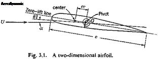
As a two-dimensional example, let us consider a strip of unit span of an infinitely long wing of uniform cross section. As shown in Fig. 3.1, let the elastic restraint imposed on this strip be regarded as a torsional spring with an axis at a point G which is fixed in space. The airfoil can rotate only about G. Assume that the spring is linear so that the torque is directly proportional to the angle of twist. Initially the “zero-lift” line of the airfoil coincides with the direction of the undisturbed flow. Let the entire system be first rotated through an angle a as a rigid body; then let the constraint be released to allow the wing to deflect elastically through an additional angle в. It is desired to find the equilibrium position of the wing (i. e. the angle в) in a flow of speed U.

The action of the aerodynamic force on the airfoil can be1 represented by a lift force, acting through the aerodynamic center, and a moment
about the same point. Let us write the distance from the aerodynamic center to the axis of the torsional spring as ec, c being the chord length and the factor e being a ratio expressing the eccentricity of the aerodynamic center (positive if the spring lies behind the aerodynamic center). Now the lift coefficient C; is proportional to the angle of attack, whereas the coefficient of moment about the aerodynamic center Cm0 is practically independent of the angle of attack.[9] Hence, the lift and moment per unit span acting on the airfoil are, respectively,

Подпись:U = qCtc = qca{6 – f a) tt ~ ‘

M0′ = qCrnS)c2 (about aerodynamic center)

where a is the lift-curve (C, vs. a) slope, q is the dynamic pressure {pU2), a is the initial angle of attack, and в is the angle of twist.

The aerodynamic moment per unit span about the axis of the spring is therefore

Ma’ = M0′ + L’ec = qc2Cm0 + qec2a(0 + a)

= qec2ad + qec2a(ry. + Cm0/ea)

In the above equation a, is measured from the zero-lift line of the airfoil. If we define a direction corresponding to an angle — a0 = CmJea as the “zero-moment” line, and redefine the angle a as measured from the zero-moment line (i. e., take a as zero when the free stream direction coincides with the zero-moment line), then Eq. 2 becomes

Ma’ = qec2a(6 + a) (3)

When equilibrium prevails, the aerodynamic moment is balanced by the elastic restoring moment. Let IQ be the spring constant, so that the elastic restoring moment per unit span, corresponding to the twisting angle в, is Кав. On equating this with the aerodynamic moment given by Eq. 3, and solving for в, we obtain

Подпись: (4)qec2aat Kx — qec2a

For a given nonvanishing a, the angle в will increase when dynamic pressure q increases. When q is so large that the denominator tends to
zero, the angle d becomes indefinitely large, and the airfoil is “divergent.” Hence, the condition of divergence is

Подпись: Hence, a curve showing 1/6Подпись:K« – qec2a = 0 (5)

The dynamic pressure at divergence qdiv and the divergence speed Udly are given by the equations

Ka. ,, ГЖ

Подпись: Fig. 3.2. Ratio of angles of twist of an elastic wing to that of a rigid wing.

Чйіч _ ec2a End Udiv V pec*a (6)

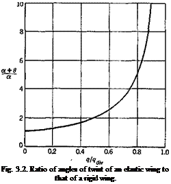
If the wing were infinitely rigid, Kx-> со; then 0 = 0. The ratio of the total equilibrium angle of attack a + в of an elastic wing to that of a rigid wing is, according to Eqs. 4 and 6,*

* [10] – ?/?div

This ratio is illustrated in Fig. 3.2. It is seen that the deflection of the elastic wing tends to be very large when q -»qdiy. When the speed of

flight is 80 per cent of the divergence speed, qlqdlv — 0.64, the wing twist is already 1.8 times the angle of attack of a rigid wing.

We may also take a different point of view as follows: Suppose that the airfoil of Fig. 3.1 be in equilibrium, so that d is given by Eq. 4. Let us ask whether this equilibrium configuration is stable. An equilibrium configuration is stable if there is a tendency to return to the equilibrium position, should the equilibrium be slightly disturbed. To test the sta­bility of the equilibrium configuration described by Eq. 4, let d be given an additional infinitesimal displacement Дd. Then the change in the aerodynamic moment is, from Eq. 2,

ДMa = qec2a Ad (8)

and that of the elastic restoring moment is

am; = Ка А в (9)

Now, if the change in the elastic restoring moment is larger than that of the aerodynamic moment, the wing will tend to return to its original position. So the equilibrium is stable if

am; > am;

If we follow the same argument, the wing will be unstable if the inequality sign reverses. The critical condition is then

am; = am; (io>

І. Є.,

qec2a AO — Ka Ad

which gives the same critical speed as Eq. 6.*

Note that AM; and AM; given by Eqs. 8 and 9 are independent of « and d. ‘Therefore the critical condition (Eq. 10) can be derived by assuming к and d to be zero. Hereafter we shall interpret d, Ma’, Me’ as the changes from the initial equilibrium values’, the symbol Д will be omitted.

Equation 6 shows that the critical divergence speed increases with increasing rigidity of the spring and decreasing chord length and eccentricity.

DIVERGENCE OF A LIFTING SURFACE

The central problem in steady-state aeroelasticity is the effect of elastic deformation on the lift distribution over lifting surfaces such as airplane wings and tails. At lower speeds of flight, the effect of elastic deformation is small. But at higher speeds of flight, the effect of elastic deformation may become so serious as to cause a wing to be unstable, or to render a control surface ineffective, or even to reverse the sense of control.

In this chapter, we shall treat in detail the problem of wing divergence, which is probably the simplest of all aeroelastic problems. Many funda­mental concepts and methods of solution can be illustrated in this connection.

In § 3.1, the phenomenon of divergence is explained by a two-dimen­sional example. In § 3.2, the problem of the divergence of an idealized three-dimensional wing is formulated in a general form. A “strip” assumption regarding the aerodynamic force is introduced to simplify the governing equations. The mathematical nature of the problem is then pointed out and illustrated by an example. Several methods of solution are discussed. First, in § 3.3, a solution based on a semirigid assumption is given. Second, in § 3.4, the semirigid assumption is reconsidered in the light of generalized coordinates. Third, in § 3.5, a process of successive approximation is discussed. The last method is mathematically more satisfactory; its convergence can be proved, and the relation between the successive approximations can readily be seen. Finally, in order to provide a practical numerical method of solution, the method of matrices is suggested. The basic concepts and definitions of matrix calculus is outlined in § 3.6, and the reduction of differential and integral equations into matrix equations according to the method of finite differences is explained in § 3.7. Some remarks regarding further refinements are made in the last section, § 3.8.

The unfortunate wing failure of Professor S. P. Langley’s famous monoplane in 1903, shortly before the Wright brothers’ successful flight, could probably be attributed to wing divergence.3-5 Monoplane designs in early aeronautical history often had divergence trouble.36 For modern aircraft, the critical speeds of flight at which divergence sets in are usually higher than those of flutter or other aeroelastic instabilities.

Hence the divergence speed itself is often, of minor importance. However, it is a convenient reference quantity for other aeroelastic phenomena; it enters into expressions for the effect of elastic deformation on lift distribu­tion, static and dynamic stability of the airplane, etc. Moreover, since the calculation of the divergence speed is relatively simple, it is generally made in the course of airplane design.

PREVENTION OF AEROELASTIC INSTABILITIES

Aeroelastic oscillations cannot always be prevented. But it is desirable to limit the amplitude of oscillation within a safe bound for the entire range of flow speeds. For a cylindrical body, the resonance oscillation between the structure and the shedding vortices can be avoided by pro­viding the structure with sufficient stiffness, so that the natural frequency of the structure is much higher than the frequency of the vortices. For an unstable aerodynamic section, the only way of preventing large ampli­tude oscillations is to provide sufficient damping in the system. For a suspension bridge, instability occurs when the reduced frequency of the bridge falls below a critical value, and can be stabilized by raising its natural vibration frequency. Stiffening and damping are the two most useful methods in controlling aeroelastic oscillations. Dampers, however, must be used with care, for they can be destabilizing. Cf. §6.11, p. 242.

One of the most important factors in aeroelasticity is the geometrical shape of the structure. In a civil engineering structure, aerodynamic forces being undesirable (unlike in airplane structures), an ideal section is one that produces no lift and small drag.

The application of this idea can be illustrated by the design of the Second Tacoma Narrows Bridge.2-11’2-12 The new design uses deep open trusses as the stiffening members (instead of plate girders), open trussed floor beams (instead of solid), and streamlined rail sections. Trusses, with small frontal area, are clearly aerodynamically ineffective. Tests in the laboratory for the new design showed complete stability even at higher angles of attack (up to 15°). These tests also revealed that the concrete deck, fitted with open steel grid slots of varying widths between each of the four traffic lanes and at the curb, has remarkable benefit.

On the other hand, one may try to design the structure streamlined so

that no separation occurs. Then, flutter, if any, will be of the “classical type” whose critical speed is higher than that of the stall flutter and can be predicted with good accuracy.

It is generally beneficial for aeroelastic stability to design the structure so as to have the least projected frontal area against wind. Decreasing the projected area decreases the magnitude of the aerodynamic forces. This follows from the fact that the aerodynamic forces are proportional to the vorticity strength, which in turn is proportional to the profile drag. A reduction in projected frontal area reduces the profile drag, and hence reduces the effective aerodynamic force.

THE H-SHAPED SECTIONS

A series of interesting experiments on oscillating H-shaped sections was performed by von Karman and Dunn.2-21,222 (The original Tacoma Bridge section is H-shaped.) When an H-shaped section is suspended in a flow, vortices are shed from the leading and trailing edges. Three types of self-excited oscillations are of interest: (1) vertical, (2) torsional, (3) coupled vertical and torsional. For the first type quantitative results are available. Some salient features will be described below, although, because of the limitation of space, the details of the experiments cannot be presented. Attention should be directed to the qualitative features that reveal the effects of intrinsic nonlinearity of a separated flow. A satis­factory theory has not yet been advanced. Nor have the experiments been comprehensive enough to permit sweeping generalizations. The problem is, at present, one of the most challenging and worthy fields of research.

Vertical Oscillations. It appears that the vertical oscillation is deter­mined by the following conditions:

1. While the structure is at rest, the vortex frequency is controlled by the wind.

2. At certain discrete wind speeds—which we designate as the “critical speeds”—the vortex frequency will either coincide with or be a multiple of one of the frequencies of motion of the structure. Such coincidence results in self-excited oscillations.

3. Beyond the critical wind speeds, the oscillating structure and not the wind speed controls the vortex frequency. In such instances the oscilla­tion extends over certain finite ranges of wind speed. The lower limit of each range is a critical speed. The upper limit is not so well defined. •However, between the upper limit and the next critical speed the structure is practically at rest.

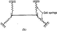
These statements are based on wind-tunnel experiments on an H-shaped section model suspended by coil springs221 (see Fig. 2.7). In these experiments vortex-frequency measurements were made with a hot-wire anemometer, both when the model was held stationary and when it was allowed to oscillate.*

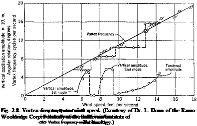
A typical result is shown in Fig. 2.8, which indicates that, as the vertical motion starts, the vortex frequency has a well-defined constant value; in other words, here the model controls the frequency. It appears that this constant vortex frequency exists only over a limited range of wind speed;

* The hot-wire was placed immediately behind the upstream girder (about one inch aft and slightly above the upper edge of the girder. The dimensions of the model are shown in Fig. 2.7. The Reynolds number based on the chord length is of order 105.

THE H-SHAPED SECTIONS

THE H-SHAPED SECTIONS

THE H-SHAPED SECTIONS

Fig. 2.7. Experimental arrangements in Dunn’s tests.


THE H-SHAPED SECTIONS

i. e., as the wind speed is increased, a point is reached at which the model is no longer capable of controlling the vortex frequency, and the wind again becomes the controlling factor. Similarly, in torsional oscillations the vortex frequency also becomes constant as motion starts; but in this instance it shifts suddenly to a higher value as the wind speed exceeds certain limits.

Figure 2.9 shows amplitude-response curves for a different set of suspending springs, supporting a similar model in an arrangement as shown in Fig. 2.7. Here n0 denotes the frequency in which the model moves vertically as a single unit, and nv n2 denote those of rotations about the z and x axes, respectively (see Fig. 2.7a). The figure shows that, when the wind speed is less than 6 ft per sec, no motion of the model is notice­able. As the wind speed U is increased gradually beyond 6 ft per sec, the

THE H-SHAPED SECTIONS

Fig. 2.9. Amplitude response of a model with three modes of oscillation (coil springs supported). (Courtesy of Dr. L. Dunn.)

amplitude of the vertical motion gradually increases, while the model oscillates at the frequency n0. At about 7 ft per sec, however, the vertical motion stops. As U is increased to 8.5, rotational oscillation about the z axis with frequency n1 starts and gradually increases its amplitude as U increases. Then it is shifted to rotational oscillation about the x axis at frequency n2 at U = 9.4. This torsional oscillation seems to increase indefinitely with U but may be stopped by external damping. At U = 12, vertical oscillation with frequency я0 appears again, which is followed in succession by rotational oscillations about the г and x axes, as shown in the figure. Thus it indicates that, for a given frequency, there are two critical speeds. With increasing wind speed various modes of oscillation appear and disappear in succession. Then the cycle repeats as the wind speed is increased further.

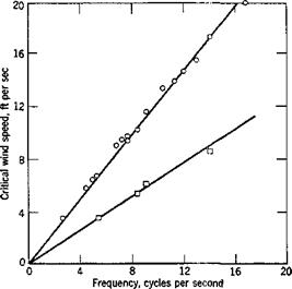
The wind speeds at which the amplitude-response curves first intersect the abscissa in Fig. 2.8 or 2.9 may be called “critical wind speeds.” As functions of frequency the critical speeds are shown in Fig. 2.10. It is seen that a linear relationship exists for each of the two values of the

critical speed. Furthermore, the first critical speed is just half of the second. The critical wind speed divided by the product of frequency and chord length (proportional to the slope of the straight lines in Fig. 2.10) is the critical reduced speed. Its inverse is the critical reduced frequency. The higher of the two critical reduced frequencies computed from Fig.

2.10 agrees with that of the vortex shedding, which is a function of the geometry of the body, and is independent of the elasticity of the supporting structure. The fact that there exist two distinct values of critical reduced

THE H-SHAPED SECTIONS

Fig. 2.10. The critical wind speeds as a function of frequency for vertical oscillations. (Courtesy of Dr. L. Dunn.)

speeds and that they differ by a multiple of 2 indicates that the oscillations are of the nature of a subharmonic resonance.

Torsional Oscillations. The most important feature of the self-excited torsional oscillations (about the x axis in Fig. 2.7) of an elastically sup­ported H-shaped section is the possibility of being “catastropic.” That is, at wind speeds in excess of certain critical value, the amplitude of oscillation can become very large.

Available data, however, are not sufficiently comprehensive to explain the basic phenomena.

Application to Suspension Bridges. Of all the oscillations that a girder – stiffened suspension bridge (H-shaped section) may suffer, the torsional oscillation is the most dangerous, because, once the critical reduced speed is exceeded, the destabilizing aerodynamic force may become very large.

Since H-shaped sections are susceptible to torsional instability, their use should be avoided whenever possible. However, the critical reduced speed can be raised considerably if the girder depth of the H-shaped section is reduced to a small value.

On the other hand, a truss-stiffened suspension-bridge section behaves more or less like a flat plate, and torsional instability develops when the angle of attack of the wind to the bridge roadbed is close to the stalling angle of the bridge section (or order 7 to 10°), whereas at smaller angles of attack, flutter of the classical type, involving coupled vertical and torsional motions, may occur.

Considerable amount of theoretical and experimental data have been obtaired by Farquharson, Vincent, Bleich, and others.2-12_2-16

THE OSCILLATION OF CYLINDRICAL STRUCTURES IN A FLOW

In the preceding section, it is seen that asymmetry develops itself in a flow around a circular cylinder if the Reynolds number is sufficiently

large. A lift force, perpendicular to the direction of flow, is created by the unsymmetric flow. Should the circular cylinder be stationary, there will be no exchaflge of energy between the cylinder and the flow. But, if the cylinder oscillates in phase with the lift force, the fluid will do work on the cylinder through the lift force, and energy will be extracted from the flow and imparted to the cylinder. The oscillation of the cylinder can then be built up.

Подпись: V Подпись: Oscillation of a cylinder. Подпись: '' X

Let us consider a two-dimensional cylinder of unit length supported by a spring and a dashpot (Fig. 2.5). Let the spring constant be K, the mass

Fig. 2.5.

per unit length m, and the ratio of the damping constant to the critical damping y* If the cylinder oscillates in still air, the natural frequency to0 (radians per second) will be given approximately by the equation

The equation of motion of the cylinder in a flow is then

Подпись: (1)d2x dx 1

where F(t) is the aerodynamic force per unit length acting on the cylinder, and x is the transverse displacement (perpendicular to the direction of flow) of the cylinder. Now F(t) consists of the lift force acting on the

* For a free-vibration system governed by the equation

mx + (Sac + Kx = 0 ((9 > 0)

the motion will be periodic if (S < (Scr, and aperiodic if (S > (Scr, where the critical damping f! CI is given by

(SCr = 2 VmK — 2 mco0

to0 = VKjm being the frequency (radians per second) of the system without damping.

It is often convenient to write (S as y/Scr. Then, if we divide through by m, the equation of motion can be written as

ac + 2yw0x + <о0гх – 0

cylinder due to shedding of vortices and the apparent mass force of the air

7fd^ d2x

surrounding the cylinder. The latter is equal to p where p is the

density of the air. Let us assume that the apparent mass of air is negligible in comparison with the mass of the cylinder m. (Otherwise we may simply modify m to be m’ = m + рттс12ІА.) F(t) is then regarded as the lift force alone. (The drag has no effect on the transverse oscillation.) By dimensional analysis, F(t) can be written as

F(t) = p U2CLd (per unit length of cylinder) (2)

Now the lift coefficient CL excited by the shedding of vortices can be written in the complex form

cL = Curl (3)

where о) is the frequency (radians per second) of the vortices on each side of the cylinder.[8] си is related to the Strouhal number by

w = Ukld (4)

Hence, we may write

/72-vi /fvi 1

— + 2yco0 — + u>2x = —pU2 dCL0 еш (5)

The steady-state solution of this equation is, according to § 1.8,

Подпись: (6)Подпись: (7)x(t) = Ad^1’^

where

a _ P dCL0_____________________

2mo)2 [(1 – О2)2 + (2у£ї)2]’Іг

со forcing frequency

co0 undamped natural frequency

^arctan(_^L)

Подпись: Q: THE OSCILLATION OF CYLINDRICAL STRUCTURES IN A FLOW Подпись: (8)

The amplitude of the response x(t) is given by A, to which the stress in the spring is proportional. Now, by Eqs. 4 and 7,

„ ud

R = — v

Hence the dependence of A on U is rather complicated.

Подпись: (d ~ 30 in., co0 = 2.5 cycles per second).

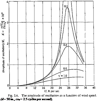
Let us consider a numerical example of a pipe line with d = 30 in. and coq = 2.5 cycles per second. Then R = 16 x 103(У. Using the data given by Relf and Simmons (Fig. 2.4), we obtain the amplitude response

A as a function of U and у by substituting О into Eq. 7. The result is shown in Fig. 2.6. It is seen that maximum amplitude is reached when U is approximately 28 ft per sec or 19 mph while the frequency ratio О is approximately 1.

The calculated amplitude response near and beyond the wind speed at which the maximum response occurs is somewhat doubtful, because in that Reynolds number range the flow is turbulent, and the power spectrum of the wake is no longer a sharp line. In other words, the wake frequency is no longer sharply defined. The flow and the lift force are stochastic

processes and must be analyzed accordingly. The real response curves are probably flatter than those given by Fig. 2.6.

The value of CL0 is of the order of 0.63 if the Reynolds number of flow lies between 40 and 3 x 10⁵.

The above calculation is based on the experimental values of к obtained on a stationary cylinder. Hence, the calculation is valid only when the amplitude of oscillation is infinitesimal. If the amplitude is finite, additional aerodynamic force associated with the shifting of the points of separation on the cylinder during the oscillation will become important. Such additional lift is, in general, a nonlinear function of the amplitude. An example of how the motion of the structure may affect the shedding of vortices and the characteristics of aeroelastic oscillations will be given in the next section in connection with the H-shaped sections.

Resonance Condition. The example given above shows that the maxi­mum amplitude of oscillation is reached in the neighborhood of Q = 1;

i. e., when the frequency of shedding vortices agrees with the natural frequency of the structure. This gives an easy rule for estimating the character of the structure as follows: Let us define a Strouhal number of the structure: .

k = (Q)

^Stru rj v-v

^max

where co0 is the fundamental natural frequency (radians per second) of the structure in still air, d is the characteristic length (here the diameter of the cylinder), and t/raax the expected maximum speed of flow (i. e., the highest wind speed). Determine the maximum Reynolds number R — t/max djv. From Fig. 2.4 find the corresponding к of the shedding vortices. Let this к be denoted by kCT; then large amplitude resonant oscillation will not occur if £stru is greater than kCI by a sufficiently large margin.

Applications to Three-Dimensional Structures. The two-dimensional model treated above may be regarded as a typical section of a three – dimensional structure. For an example of an overground pipe line, m may be taken as the mass per unit length at the center span, co0 the funda­mental natural frequency of the pipe line, and у the ratio of the actual damping to the critical damping when the pipe line oscillates in the fundamental mode. For a smokestack, the typical section may be taken at three fourths of its length above ground.

Generalization of the analysis to three-dimensional structures can be made without difficulty. The simplest approach is to use generalized coordinates and Lagrange’s equations. However, the effect of a free tip on the fluctuating aerodynamic force is both profound and difficult to predict. Rash calculations without due account of the tip-effect can be dangerous.

THE FLOW AROUND A CIRCULAR CYLINDER

The theoretical investigation of the vortex pattern which is observed in the wake of a cylinder was originated by von Karman2-24 who considers a double row of vortices in a two-dimensional flow (Fig. 2.3). The equi­librium configurations (the patterns that can maintain themselves in the

flow) and the stability of the equilibrium configurations against infinites­imal disturbances, (displacements of individual vortices), are studied. It is found that the double row of vortices is stable only if the vortices in one row are opposite to points half way between the vortices in the other row, and if the distance between the rows is 0.281 times the distance between two consecutive vortices in each row. Such an arrangement of vortices is known as a Karman vortex street.

The theoretical treatment of the vortex street based on the assumptions of a perfect fluid cannot reveal the Reynolds-number effect, whereas measurements do indicate definite effect of the Reynolds number on the flow pattern.

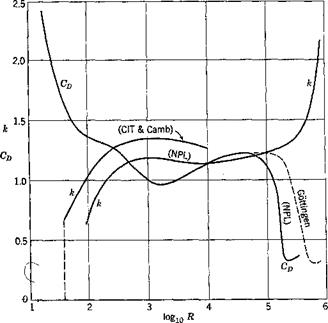
In a flow past a long circular cylinder, a great variety of changes occur with an increasing Reynolds number* R. At low values of R the flow is smooth and unseparated, but the fluid at the back of the cylinder is appreciably retarded. At higher values of R two symmetrical standing vortices are formed at the back. With increasing Reynolds number these vortices stretch farther and farther downstream from the cylinder. Even­tually the standing vortices become considerably elongated and distorted. When R reaches a number of order 40, the vortices become asymmetrical, detach from the obstacle, and move downstream as if they were discharged alternately from the two sides of the cylinder. In this way an eddying motion in the wake is set up. As the flow moves downstream, the eddying motion is gradually diffused and “decays” into a general turbu­lence. For R in the range of 40 to 150, the “shedding” of vortices is regular. The eddying motion in the wake is periodic both in space and time. The flow can be approximated by a Karman vortex street. The range of R between 150 and 300 is a transition range, in which the vortex shedding is no longer so regular as before. Its frequency appears to be somewhat erratic. For R > 300, the vortex shedding is “irregular.” A predominant frequency can be easily determined, but the amplitude appears to be more or less random. In addition, “background” random fluctuations, similar to turbulences behind a grid in a wind tunnel, becomes more appreciable. The kinetic energy of fluctuations in the wake is partly contained in the periodic motion and partly carried by the turbulences. As R increases, more and more of the energy is transferred to the turbulences. Finally, at R of order 3 x 10s, the separation point of the boundary layer moves rearward on the cylinder. The drag coefficient of the cylinder decreases appreciably owing to this important change (see Fig. 2.4). The flow in the wake at these large Reynolds numbers becomes so turbulent that the vortex street pattern is no longer recognizable.

The diameter of the cylinder is taken as the characteristic length.

The geometry of the wake, when the Reynolds number is in a range in which vortices may be regarded as “shedding,” is as follows: The fre­quency at which the vortices are shed, expressed nondimensionally as the Strouhal number2 23 k, is a function of the Reynolds number. Here the Strouhal number к shall be defined[7] as cod/U, where to is the frequency in radians per second and d is the diameter of the cylinder. The results of Relf and Simmons2,25, Kovasznay2,26, and Roshko2’2′ are given in Fig. 2.4, from which the value of к for each R can be found. f The number

THE FLOW AROUND A CIRCULAR CYLINDER

Fig. 2.4. Variation of the Strouhal number and drag coefficient against Reynolds number for a circular cylinder. CD and R are based on the diameter of the cylinder. Sources of data are: NPL; Relf and Simmons, Aeronaut. Research Com. R. & M. 917 (1924). Cambridge; Kovasznay, Proc. Roy. Soc. A. 198 (1949). CIT; Roshko, NACA Tech. Note 2913 (1953). Got­tingen; Ergebnisse A VA Gottingen, 2 (1923).

of vortices n = w/Itt, shed from each side of the cylinder, is

n = per second (1)

2irdv

The distance A between two consecutive vortices in a row is

U — v Iv

A=———- 0.25 to 01 (2)

n U /

where v is the relative velocity of the vortices with respect to the free stream. The ratio of the distance #hetween the rows of vortices to the distance A is approximated by von Karman’s theoretical formula H = 0.281A at small distance from the cylinder, but H/A increases as the distance from the cylinder increases. At large distance H/A is of order 0.9. The intensity of the velocity fluctuations is small close behind the cylinder. The maximum intensity of the fluctuations occurs in the vicinity of 7 diameters downstream. Thus it appears that the vortices are not really “shed” from the cylinder, but are developed gradually.

The range of Reynolds numbers of interest in aeroelasticity is the range in which the flow fluctuates, i. e., for R > 40. At a large Reynolds number, say R> 3 x 10®, or at a distance far downstream of the cylinder, although no distinct vortex pattern can be observed, the flow is turbulent and can still excite oscillations in an elastic structure.

In the subcritical Reynolds number range (R <3 x 10°), a periodic lift force (perpendicular to the flow) acts on the cylinder; the root-mean – square value of the lift coefficient (lift force/unit span)/(|pt/2-diameter), V=C?> is of the order of 0.45. In the Reynolds number range 0.3 x 10⁶ to 3 x 10⁶, the lift is no longer a periodic function of time, but becomes random, the root-mean-square value of the lift coefficient ranges from 0.03 if the cylinder surface is highly polished and the section is far away from a tip, to 0.13 if the surface is not polished. Near a tip of a structure aiarge variation of lift may occur. Thus a rocket with a spherical nose may have 4 or 5 times as much lift as one with a conical nose. The un­steady component of the drag coefficient at such large Reynolds number has a root-mean-square value of the order of 0.03. At Reynolds number greater than 3 x 10е, periodicity reappears in the wake and the mean drag coefficient rises again to 0.7 or 0.8.