Category An Introduction to THE THEORY OF. AEROELASTICITY

GENERAL CONSIDERATIONS IN AERODYNAMICS AND THE DIMENSIONLESS COEFFICIENTS

In order to discuss aeroelastic oscillations associated with the shedding of vortices, it is necessary to consider the effect of the viscosity of the fluid. In the flow of a nonviscous fluid the possibility of slip between the fluid and a solid body in contact with the fluid may be assumed. But such a relative velocity is impossible in a viscous fluid: The velocity of the fluid in contact with the solid must be exactly the same as that of the solid itself. This nonslip condition persists, no matter how small the viscosity of the fluit^fas long as the characteristic length of the body is much larger than the mean free path of the fluid molecules. But, when the viscosity is small, its effect is felt only in a thin layer next to the solid body: the boundary layer, in which the velocity of flow changes rapidly from the velocity of solid surface to that of the free stream. Outside the boundary layer, the fluid may be regarded as nonviscous, (see Fig. 2.2 in which the scale normal to the solid wall is greatly exaggerated).*

* The boundary layer thickness <5 in Fig. 2.2 is defined by the condition that, when the distance from the solid wall is (5, the retardation of the velocity of flow due to the skin friction is 1 per cent of the potential flow velocity; i. e., at S, the velocity attains 0.99 of the potential value. For a given body, the boundary-layer thickness decreases as the Reynolds number increases. At higher Reynolds number, the flow in the boundary layer is laminar near the leading edge, but becomes turbulent behind a transition point. As shown in Fig. 2.2c, the transition point moves forward as the Reynolds number increases. A turbulent boundary layer can resist an adverse pressure gradient better than a laminar one, and separation over an airfoil can be delayed.

The flow in the boundary layer is pulled forward by the free stream, but is retarded by friction at the solid wall. It is also retarded by an adverse pressure gradient, if such a gradient exists. If the adverse pressure gradient is sufficiently large, the flow may be interrupted entirely, and the

GENERAL CONSIDERATIONS IN AERODYNAMICS AND THE DIMENSIONLESS COEFFICIENTS

GENERAL CONSIDERATIONS IN AERODYNAMICS AND THE DIMENSIONLESS COEFFICIENTS

Fig. 2.2. Boundary layer, (a) Mean velocity distribution in a boundary layer, (b) Laminar boundary layer over an ellipse and an airfoil. The boundary layer thickness <5 is magnified by a factor VR/100, where R — Ucjv is the Reynolds number based on the chord length. The small circle over the upper surface marks the separation point. (c) Points of transition from laminar to turbulent flow in the boundary layer, as a function of the Reynolds number. (From H. Schlichting, NACA Tech. Memo. 1218.)

boundary layer may detach from the solid wall. The flow is then said to be separated.

An adverse pressure gradient exists in a flow around a bluff body, such as a cylinder or a sphere. For a streamlined body, such as an airfoil, the rear part of the body is very thin and has very gentle curvature; the adverse pressure gradient is small, and separation can be prevented. A streamlined body maintains a smooth flow when it is properly situated in
the flow; but, when the angle between the chord and the undisturbed stream is sufficiently large, separation may still occur.

GENERAL CONSIDERATIONS IN AERODYNAMICS AND THE DIMENSIONLESS COEFFICIENTS
GENERAL CONSIDERATIONS IN AERODYNAMICS AND THE DIMENSIONLESS COEFFICIENTS GENERAL CONSIDERATIONS IN AERODYNAMICS AND THE DIMENSIONLESS COEFFICIENTS

The above physical picture explains why the Reynolds number is so important in determining the condition of flow around a bluff body and the force acting on it, because the Reynolds number expresses a ratio between the inertia force and the friction force. A flow pattern is deter­mined by the interplay among the pressure gradient, friction, and inertia. As these three forces are subject to the condition of equilibrium, only two of them are independent, and we may select the friction and inertia as independent influences. The inertia force has components of the form

and, hence, for a given flow pattern, must be proportional to the products pU2jl, where U is a characteristic velocity, and / a characteristic length. On the other hand, the friction force has components of the form у(д2и/ду2), and, hence, for a given flow pattern, must be proportional to yU/l2. (Э2m means a small difference of velocity of the second order, and is therefore proportional to the velocity U, whereas Эy2 is the square of a small difference in length and is proportional to /2.) The ratio between these two forces is therefore

PU2 . yU pUl
І ~ l2 ~ у

which is the Reynolds number.* A small value of Reynolds number means that friction forces predominate; a large value that inertia forces predominate.

SOME TYPICAL EXAMPLES OF AEROELASTIC OSCILLATIONS

SOME TYPICAL EXAMPLES OF AEROELASTIC OSCILLATIONS
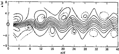
Whoever has rowed a boat must have observed the trail of vortices leaving the oar. One can easily perform an experiment by moving a stick in water with sufficient speed and observe the wake. In the wake the flow is turbulent, but a vortex pattern can be seen (Fig. 2.1). These vortices are “shed” alternately from each side of the stick. This shedding of vortices induces a periodic force in the direction perpendicular to the line of motion, and the stick wobbles back and forth. Similar action occurs on any cylindrical body with a blunt nose or tail. The frequency

of the wake vortices is determined by the geometry of the body and the speed of flow. If the frequency is close to the natural vibration frequency of the body, resonance will set in.

Among examples of engineering significance, the most familiar is probably the oscillation of telephone wires,2’7 with high frequency and small amplitude, producing musical tones. Smokestacks,2’3 submarine periscopes,21 oil pipe lines,2 2 television antennas,21 and other cylindrical structures2-7 often encounter vibrational troubles of aeroelastic origin. These may be cured either by stiffening the structures so that the natural frequency is much higher than the frequency of the vortex shedding in
wind or by introducing vibration dampers into the system to absorb the energy.[6]

A different type of vibration is the “galloping” of transmission lines.2-4-2-5 During a sleet storm a transmission line may vibrate in a strong wind. The cable span oscillates sometimes as a whole, but more frequently with one or more nodes in a span. When the oscillations become severe, the cables move irregularly, but freely, through vertical distances of as much as 20 to 35 ft in a span of 500 ft. The phenomenon cannot be observed every day, nor can it be seen at any specific place; it appears and dis­appears suddenly. Once started, it is very persistent. Sometimes it may continue for 24 hours. The cause of galloping has been shown to be the sleet on the conductors. The ice forms a cross section of a more or less elliptical shape, with the major axis perpendicular to the wind direction. Such a section is unstable in an airstream: the aerodynamic force exerts a “negative damping" component so that, once the oscillation is started, it will continue to build up. – The observed frequencies of oscillation are close to the natural frequencies of the span. The vibration will stop when the ice is broken and thrown off the line.

Since vibrations of this type are originated from unfavorable aero­dynamic configurations, they can be avoided by preventing such unfavor­able configurations from occurring. For transmission lines, however, a satisfactory solution has not yeFfieen found.

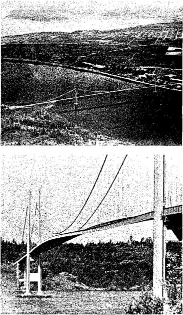
The two types of aeroelastic oscillations considered above are character­ized by a separated flow in the rear of the body, i. e., a flow that does not follow the contour of the solid body. Let us now consider another type of self-excited oscillation which does not necessarily involve flow separa­tion. This is the flutter. The best example occurs in the field of aero­nautics where streamlining is a rule and flow separation is avoided. In civil engineering, suspension bridges sometimes have sufficiently clean contours so that the flow may be considered as essentially unseparated; but, as a rule, separation does occur over part of the body or during part of the oscillation cycle; hence the name stall flutter. The failure of the original Tacoma Narrows Bridge210 is generally believed to be due to stall flutter. This bridge was a suspension structure, with a center span of 2800 ft, two side spans of 1100 ft each, and a width of 39 ft center to center of cables. The cables had a sag ratio of 1/12. The stiffening structure was of the plate-girder type. Vertical oscillations of consider­able amplitudes were first observed during the erection of the suspended

SOME TYPICAL EXAMPLES OF AEROELASTIC OSCILLATIONS

Stall flutter of the original Tacoma Narrows Bridge, Puget Sound,
Washington. (Courtesy of F. B. Farquharson)


SOME TYPICAL EXAMPLES OF AEROELASTIC OSCILLATIONS

The failure of the original Tacoma Narrows Bridge, Nov. 7, 1940.
(Courtesy of F. B, Farquharson)


SOME TYPICAL EXAMPLES OF AEROELASTIC OSCILLATIONS

floor and continued, at intervals, until the day of failure, but no damage was done. On November 7, 1940, four months after the bridge was opened to traffic, suddenly at a wind speed of 42 mph, the center span developed a torsional movement with a node at mid-span. (There was, however, considerable motion at the mid-point.) The frequency of oscillation suddenly changed from 37 to 14 cycles per minute. The motion grew violently, and failure occurred half an hour later.

A lesson learned from the Tacoma Bridge is the recognition of the importance of aeroelastic investigations in structural design. The conven­tional design procedure focuses mostly on the strength of a structure, whereas the aeroelastic design focuses on the rigidity, damping character­istics, and the aerodynamic shape. Hence there exists a different point of view.

The three types of oscillations illustrated above can occur in a uniform flow without external disturbance. For that reason they are often said to be self-excited.

SOME AEROELASTIC PROBLEMS IN CIVIL. AND MECHANICAL ENGINEERING

Aeroelastic oscillations are generally sustained by aerodynamic forces induced by the structure itself. Many types of structures may develop excessively large elastic deformation, or suffer sustained or divergent oscillations in certain ranges of wind speeds. For a structure designed to maintain static equilibrium such aeroelastic trouble can be serious.

The failure of the original Tacoma Narrows Bridge is an example of aeroelastic oscillation. If the wind speed and the mode and frequency of the structural oscillation are such that energy can be absorbed from the wind by the structure, and if the energy absorbed is larger than that dissipated by the structural damping, the amplitude of oscillation will continue to increase and will finally lead to destruction. The Tacoma Narrows Bridge failed at a wind speed of 42 mph, whereas the structure as built should have been able to resist a steady wind of at least 100 mph if no oscillation had occurred. Since all structures exposed to wind oscillate under some disturbances, it becomes apparent that it is essential for the designer to predict the critical wind speed at which the structure may become aeroelastically unstable.

In this chapter we shall outline the general principles of aeroelasticity for some civil and mechanical engineering applications. The main character of the problems discussed in this chapter is that the structures concerned are mainly unstreamlined and hence unamenable to theoretical treatment. We must rely heavily on experimental results to understand the nature of the aerodynamic forces.

Several typical examples of aeroelastic oscillations are given in §2.1. Some aerodynamic considerations are given in § 2.2. The flow around a cylinder is then reviewed in § 2.3. The aeroelastic oscillation of a cylin­drical body is treated in § 2.4, and that of an H-shaped section is discussed in § 2.5. Finally, means of preventing aeroelastic instabilities are discussed in § 2.6.

COUPLED TORSION-FLEXURE OSCILLATIONS OF A CANTILEVER BEAM

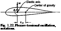
Подпись: Fig. 1.22. Flexure-torsional oscillation, notations.

We shall show that the oscillation of a beam whose elastic axis and line of centers of gravity do not coincide is always “coupled”; i. e., it is a combination of flexure and torsion. Let xa be the distance between the elastic axis and the line of center of gravity (Fig. 1.22). Assume that the elastic axis is a straight line and that the deflection of the elastic axis is

restrained to the vertical direction only. Let the vertical deflection be w and the rotation of the beam cross sections about the elastic axis be 6. Then the equations of motion are, according to Eqs. 5a and 6a of § 1.1,

COUPLED TORSION-FLEXURE OSCILLATIONS OF A CANTILEVER BEAM0)

with the usual boundary conditions of a cantilever beam:

At

У = о,

W

-Ії-в-о

ду

At

y — U

9 2и>

d3w Эб _ ~ эу3 эу

Зу2

These equations reduce to two independent ones for the purely torsional and purely flexural oscillations if xa = 0.

Again we look for particular solutions in the form

w(y, t) = A f(y)eM, 6(y, t) = B ф(у)еш (3)

Подпись: + В тхла)*ф = 0
COUPLED TORSION-FLEXURE OSCILLATIONS OF A CANTILEVER BEAM COUPLED TORSION-FLEXURE OSCILLATIONS OF A CANTILEVER BEAM

Substituting Eq. 3 into Eq. 1, we obtain

with the corresponding boundary conditions obtained by replacing w by f and в by ф in Eqs. 2. Let us first remark that, by a generalization of the Sturm-Liouville’s theorem, it can be shown that there exist real valued eigenvalues to, and hence real-valued eigenfunctions f(y) and <f>(y). With­out proving this, we may verify it a posteriori by assuming that real to, f ф exist, and then carry through the computations to show that we can obtain them.

Let f(y) and ф(у) be solutions of Eqs. 4. Multiply the first and the second of Eqs. 4 by / and ф respectively, and integrate the results with respect to у from 0 to /. The following equations are obtained:

An integration by parts and an application of the boundary conditions (Eqs. 2) transform au and a22 into the following form:

«її – сиш1 ci2aj2 C210)2 «22 — C220j2

Pw* – Qu>2 + R = о

COUPLED TORSION-FLEXURE OSCILLATIONS OF A CANTILEVER BEAM COUPLED TORSION-FLEXURE OSCILLATIONS OF A CANTILEVER BEAM Подпись: R — «II«22 Подпись: (8) (9) (10) (И)

For a nontrivial solution, A and В must not both vanish. In order that a significant solution may exist, the determinant of the coefficients of Eqs. 5 must be zero:

It can be verified that the right-hand side of Eq. 11 is always positive. We obtain, therefore, four real roots for to. Hence, four particular

solutions are obtained, each representing a simple-harmonic motion. The ratio AIB, corresponding to each root w, is obtained from Eqs. 5:

Подпись:A ^22^ #22

В cuw2 – #u c12co[5]

COUPLED TORSION-FLEXURE OSCILLATIONS OF A CANTILEVER BEAM

Thus, if f(y) and ф(у) were known, the constants #u, a12, etc., and P, Q, R can be computed according to Eqs. 6, 7,’10; and the frequency со and the ratio A/В can be obtained from Eqs. 11 and 12. To determine f(y) and ф(у), the method of successive approximation can be used. Let f0(y) and <f>Q(y) be two arbitrary functions which satisfy the “rigid” boun­dary conditions* at the clamped end у = 0, which are given by the first of Eqs. 2. Considering f0 and ф0 as approximate solutions, we determine the corresponding approximate values of #n, a12, ■ ■ ■ and со2 and A/B. Now, by a formal successive integration, Eqs. 4 may be written as

So the process of approximation can be carried out as follows: Substi­tuting /0 and ф0 into the integrands on the right-hand sides of Eqs. 13, we

obtain two new functions ~^Лу) and ф(у), which we shall call f(y)

and ф-fy). Using ffy), фх(у) as the first approximation, we determine au, #i2, etc., and со2 and A/В. If we substitute fv фг, and the new value of A/В into the integrands of Eqs. 13 and integrate, the result may be labeled /2 and ф2. The process can be repeated with f2 and ф2 as the starting approximations. When fn and фп converge satisfactorily, со2 and A/В must also converge to their true values. The rate of convergence depends on the choice of f0 and ф0. If /0 and ф0 were chosen as the fundamental modes of uncoupled flexural and torsional oscillations of a uniform beam, a sufficiently accurate result can usually be achieved in three or four cycles.

Let us assume that, in the process indicated above, we always take the smaller of the two to2 values of Eq. 11. It can be shown1-58 that, for

arbitrary choice of f0, ф0 (which satisfies the boundary conditions), the process of successive approximation converges to the fundamental mode of the coupled flexure-torsional oscillation, i. e., the mode with the lowest frequency.

If the larger of the two to2 values of Eq. 11 is taken in the successive approximation, a different set of values A/B, f(y) and ф(у) will be obtained, which would converge to the second mode of the flexure-torsional oscilla­tion. The physical meaning of the two modes can be clarified by the following illustration. Consider a beam whose center of gravity at each section lies exactly on the elastic axis (жа = 0). Such a beam can oscillate in purely flexural and purely torsional modes. If the center of gravity is moved away slightly from the elastic axis, the modes will change slightly, and the oscillation will be a combined flexure-torsional motion. With small values of жа, it is expected to have one of the combined flexural – torsional mode vary but little from the purely torsional mode, and the other vary but little from the purely flexural mode. Accordingly, one of the coupled oscillations is said to be predominantly flexural, and the other predominantly torsional.

It might appear that, if the center of gravity is moved further away, the frequencies may approach each other and finally coincide. Fora cantilever beam, however, this will never happen, because the frequencies can co­incide only if Q2 — APR = 0, and it can be verified that Q2 — APR is always positive if x* Ф 0. Hence, the roots must be discrete.

In order to obtain higher modes by the method of successive approxi­mation, the orthogonality relations among the normal modes may be used.1-52-1 05 But this subject will not be pursued further here.

The natural frequencies can be found experimentally by a resonance test. The oscillations may be excited, for example, by a rotating eccentric weight driven by a motor through a flexible shaft. Intense oscillations occur when the frequency of the motor coincides with one of the natural frequencies of the wing. As discussed above, the excited resonance oscillation is always coupled unless the elastic axis coincides with the inertia axis. But one of the modes will be predominantly flexural, and the other predominantly torsional. It is customary to call the first one flexural oscillation and the second one torsional oscillation.

TORSIONAL OSCILLATIONS OF A CANTILEVER BEAM

The equation of static equilibrium of a straight, cantilever beam in torsion is (Fig. 1.21), according to Eq. 5a of § 1.1,

Ms**

Подпись: §1 Подпись: m m' Подпись: Э TORSIONAL OSCILLATIONS OF A CANTILEVER BEAM

where в is the angle of twist, T the torque, GJ the torsional rigidity, and у the axial coordinate. If the beam is in free oscillation, ЗГ/Эу arises

dy-

Fig. 1.21. Moments acting on an element of a beam in
free torsional oscillation.

Подпись: _Э dy Подпись: (1)
TORSIONAL OSCILLATIONS OF A CANTILEVER BEAM TORSIONAL OSCILLATIONS OF A CANTILEVER BEAM

from the inertia, and is /а(Э20/Эг2), Ia being the mass moment of inertia about the shear center of the cross section. Hence, the equation of motion is

For a cantilever beam, the boundary conditions are (1) no rotation at the root, and (2) no twisting moment at the tip:

0 = 0 at у = 0

Подпись: (2)= 0 at y = l dy

A Beam of Constant Cross Section. Consider the simplest case when GJ and Ia are constants. Assuming a solution of the form

%, 0 = Ф(у)еш (3)

Подпись: where Подпись: A GJ Подпись: (4) (5)

we obtain, from Eq. 1

The general solution of Eq. 4 is

ф(у) = A sin ку + В cos ку (6)

where A and В are arbitrary constants. From the boundary conditions (Eqs. 2), we see that a nontrivial solution (ф(г/) not identically vanishing) exists only if

В = 0, cos кі = 0, A = arbitrary constant

This requires that

КІ = n —

(« =

1, 3, 5, • – •)

(7)

І. Є.,

Ig) 1 /«

(n = 1, 3, 5, • • •)

(8)

The corresponding function ф(у) is then

Подпись: (9)Подпись:. П7Т

Фп(У) = Asm—у

A general solution of Eq. 1 can be obtained by combining Eqs. 9 and 3. Writing the positive root of Eq. 8 as con and sum over n, we obtain

TORSIONAL OSCILLATIONS OF A CANTILEVER BEAMsin ^ (Апеіш-С + Впе~ІШп1) (10)

П

where An and Bn are arbitrary constants. The real part of Eq. 10 gives the general solution as a real-valued function in the form

6(2/, 0 ==2sin ^ (Cn cos a>nt + Dn sin qjJ) (11)

П

The particular values con are called the eigenvalues (or the characteristic values) of the problem, and the corresponding фп(у) are the eigenfunctions (or the characteristic functions). As long as the coefficient A in Eq. 9 is arbitrary, the eigenfunctions have unspecified magnitudes. When some special rule is given, so that the amplitudes can be definitely defined, the eigenfunctions are said to be “normalized.” For example, we may take A to be 1. Or we may define A so that фп2(у) integrated over the span / is equal to 1; or in such a way that фп(у) becomes 1 at у = /; etc.

It should be observed that all points along the span reach their maximum or minimum amplitude at the same time; i. e., they are “inphase.” The period of the motion is Tn — 2тт/соп, and the number of oscillations per second is n = aijln.

TORSIONAL OSCILLATIONS OF A CANTILEVER BEAM

Torsional Oscillations of an Arbitrary Beam with Damping. The general case of torsional oscillation of an arbitrary beam with damping force proportional to the angular velocity can be solved approximately by a number of methods. Here we shall not discuss the methods of solution, but will investigate a general feature of the oscillation of such a beam. The equation of motion is

where GJ, /?, and Ia are functions of y. Equation 12 can be solved by assuming, as in Eq. 3,

%, t) = Ф(у)еш (13)

and determining the eigenvalue со from the solution ф(у) and the boundary conditions. Depending on the sign of (}, the motion is either damped or amplified as time increases. The eigenvalue со is, in general, a complex number. If we substitute Eq. 13 into Eq. 12, and cancel the factor elat, the result may be written as

where yfy) and щіу) are real functions. Since this is an equation with complex coefficients, the solution <f>(y) will be complex and can be written as

ф(.У) = Фі(у) + і Ф4-У) (15)

where фііу) and ф2(у) are real functions. Therefore a solution of (12) that satisfies the boundary conditions is

Oi = ШУ) + іфМУШІ (16)

But Eq. 12 is an equation with real coefficients; hence, there must exist another solution, conjugate to 6V which also satisfies the boundary con­ditions because the real and imaginary parts of вг satisfy these conditions separately. The general solution is the sum of these two particular solutions multiplied by two arbitrary constants. The solution can be written in the real form %> 0 = {Ifi Фі(У) ~ c2 ФзШ cos qt – [q ф2(у) + c2 фг(у)] sin qt}ept (17) where

ico = p + iq Let

ф(У) = ^ФЛУ) + ФЛУ)> ‘і%) = arc tan

Фі(У)

then Eq. 17 can be written as

%, t) = 2Ф(y)ept{c1 cos [qt + T(y)] – c2 sin [qt + T(y)]} (18)

The meaning of the function T(y) can be clarified by considering the time at which в(у, t) becomes zero; i. e., when the cross section at у passes through the equilibrium position. Setting 6(y, t) equal to zero and solving for t, we obtain

Подпись: П7ГПодпись: (19)Подпись:1 c

t = – arc tan — — ‘F(y) q l c2

where n is any integer. The right-hand side of Eq. 19 depends on y, which means that different cross sections of the beam pass through the equilibrium position at different instants of time; the motion of the beam is out of phase.

If Y(y) is a constant, Eq. 19 will be independent of y; the beam then oscillates in phase. T(y) is a constant if the ratio yfy)lv{y) is a con­stant. It can be shown that the necessary and sufficient condition for an oscillation of the beam to be in phase is that the ratio of the damping coefficient fl(y) to the sectional moment of inertia Ify) be constant along the entire span.6-13

COMPLEX REPRESENTATION OF HARMONIC MOTIONS

In the discussion of periodic phenomena, it is convenient to use the complex representation. Consider a quantity x which varies periodically with frequency m (radians per second) according to the rule:

x — A cos (tot + y>) (1)

This is a simple-harmonic motion. A is called the amplitude and y> the

* For aircraft structures, see Scanlan and Rosenbaum.1-67 For general principles, see Den Hartog,1-62 Timoshenko.1-69 Myklestad’s book1-66 treats the numerical aspects of the analysis.

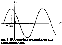
phase angle. It is customary to regard x as the projection of a rotating vector on the real axis (see Fig. 1.19). The length of the vector is A and its angle with the x axis is cot + f – The vector rotates counterclockwise with angular speed со. Since such a vector is specified by two com­ponents, it can be represented by a complex number. For example, the vector in Fig. 1.19 can be specified by the components a; = A cos (cot + ip), and у = A sin (cot + ip), and hence by the complex number x + iy. But

eH<at+y>) _ cos _}- y) _|_ / sin (+ ip) (2)

so the rotating vector can be represented by the complex number

x + iy = Aei(a, l+v) (3)

Подпись: Fig. 1.19. Complex representation of a harmonic motion.
COMPLEX REPRESENTATION OF HARMONIC MOTIONS

The quantity x given by Eq. 1 is the real part of the quantity given by

Eq. 3, which is the complex representation of Eq. 1. The imaginary part of Eq. 3 represents another simple harmonic motion.

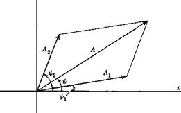
The vector representation is very convenient for “composing” several simple-harmonic oscillations of the same frequency. For example, if

x = A1 cos (соїt + щ) + A2 cos (cot + ip2) — A cos (cot + ip) (4)

then x is the resultant of two vectors as shown in Fig. 1.20. The com­ponent A 2 cos (cot + f2) is said to lead the component Аг cos(cof + ірг), if, as shown in the figure, ip2 > Wi – Hereafter we shall write x given by Eq. 1 in the complex form

x = (a + іЬ)еш = Aei(",ti’l’) (5)

where

A = Va2 + b2, tan y> = –

a

It is understood that the physical quantity is given by the real part of the complex representation.

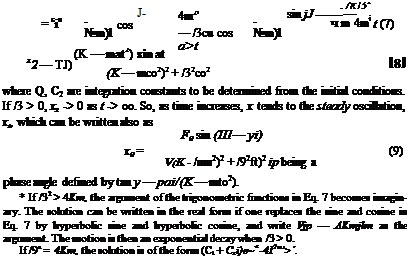
where, if /32 < 4Km*

Since the vector і leads the vector 1 by an angle tt/2, a multiplication of a given vector by the imaginary number і simply means a change of phase angle to lead by tt/2.


COMPLEX REPRESENTATION OF HARMONIC MOTIONS

Fig. 1.20. Vector sum of two simple harmonic motions of the same frequency.


As an illustration, let us consider the forced oscillation of a single particle, with elastic restraint and with damping, excited by a simple – harmonic force. The equation of motion, written in real form, is


dhi dx


(6)


,Kx = Fa sin at


The solution may be written as


x = x1 + x2


COMPLEX REPRESENTATION OF HARMONIC MOTIONS

These results can be derived by using the complex representation as follows. Consider the equation

md^ + Pjt+Kx = F^ (10)

Since F0emt = F0 cos ait + ifо sin cut, the real part of x will give the solution for a periodic force F0 cos cot, whereas the imaginary part that of F0 sin <ot. Putting x proportional to eiat, we obtain

dot

m— + (}—+Kx== {т{іт)г + /?/со + K]x (11)

Подпись: where COMPLEX REPRESENTATION OF HARMONIC MOTIONS Подпись: (12) (13)

Hence we obtain the steady oscillation

The modulus of Z(/co) is V(K — mw2)2 + /?2co2, and its phase angle is ip = tan”1 [fia)/(К — тш2)]. Since x is the ratio of two complex numbers, and since we divide two complex numbers by dividing their moduli and subtracting their arguments, we obtain

FJ(M-v)

x = (14)

V(K – ты2)2 + р2ш2

NORMAL COORDINATES

The last two examples of the preceding section point out a very im­portant fact: By introducing the undamped free-vibration modes of a structure as the basis of generalized coordinates, the equations of motion can be simplified.

The theory of small free oscillations of an elastic body about an equi­librium configuration has been well developed. In particular, it suggests that, if фп{х) represents the oscillation mode* associated with a frequency <яп, and if the frequency spectrum is so arranged that <an > con_.j, {n > 1), then an arbitrary disturbed configuration u can be represented by a series

CO

n(x) = ‘S q„<f>n(x) (1)

£—4 71 = 0

with

4n = J Mx) n(x) • фп(х) dr(x) I J p(x) фп(х) • ф„(х) dr(x) (2)

* That is, the amplitude of the displacement from the equilibrium configuration at the point x. u and фп may be regarded as vectors having three components, each a function of the position vector x, if a three-dimensional elastic body is considered. In Eq. 2 et seq., the product u(x) • ф„(х) denotes the scalar product of u(x) and"^„(xl. Similarly ф„(х) ■ фт(х) is a scalar product.

J p(*) &(x) • фп(х) dr(x)

Подпись: 1 if V = n 0 ifv^n Подпись: (3)

where p(x) represents the density of the body and dr(x) represents an element of volume at x, the integration being taken over the entire body. Moreover, фп(хJ are orthogonal and can be normalized so that

We shall call фп(х) the normal modes and qn the normal coordinates. Then the kinetic energy and the elastic strain energy can be expressed, respectively, as

Т=^тпЧп

(4)

V = 2

n = 0

The constants mn are called generalized masses:

= J p(*) Фп(х) ■ фп(х) dr(x) (5)

The generalized force is

Qn = $ F(x) • ф„(х) dr(x) (6)

where the integral is again taken over the entire body, F(x) being the force acting at x.

It is clear that, when T and V are expressible in the form of Eq. 4, the inertia and elastic “couplings” between the various generalized coordinates are absent. The equations of motion can be reduced to a set of inde­pendent equations, each containing one qn, provided that all Q„ are independent of the coordinates qn.

We shall not discuss the methods of calculating vibration modes and frequencies in this book.*

GENERALIZED COORDINATES AND LAGRANGE’S EQUATIONS

In deriving the equations of motion for many problems in aeroelasticity, generalized coordinates and Lagrange’s equations are often used. The ideas of generalized coordinates are developed in the classical mechanics, and are associated with the great names of Bernoulli, Euler, d’Alembert, Lagrange, Hamilton, Jacobi, and others. There are many excellent text­books on this subject,1-54,1-68,1-69 and so we shall not explain the method in great detail. Instead, we shall survey the fundamental principles briefly, and illustrate their meaning by several examples.

The foundation of the mechanics of a single particle is Newton’s second taw of motion where F is the total force acting on the particle, and p is the linear momentum of the particle defined by the product of mass m and velocity v:

Подпись: (2)p — mv

Подпись: (/ = 1, 2, • • N) Подпись: (3)
GENERALIZED COORDINATES AND LAGRANGE’S EQUATIONS

In applying this law to a system of N particles, we must distinguish between the external forces acting on the particles due to sources outside the system and internal forces on a particle і due to all other particles in the system. Thus the equation of motion for the zth particle is[4]

where F;,e) is the external force, Ftf is the internal force on the ith particle due to the jth particle, and p£ is dpjdt. If we assume that F„ (like Ft(e))

obeys Newton’s third law that the forces the two particles exert on each other are equal and opposite and lie along the line joining the particles, then by a summation over all the particles we can show that (a) the center of mass moves as if the total external forces were acting on the entire mass of the system concentrated at the center of mass, (b) the time derivative of the total angular momentum about an origin is equal to the moment of the external force about the same point, (c) the total angular momentum about a fixed point О is the angular momentum about О of the system concentrated at the center of mass, plus the angular momentum about the center of mass, (d) the kinetic energy, like the angular momen­tum, also consists of two parts: the kinetic energy obtained as if all the mass were concentrated at the centre of mass, plus the kinetic energy of motion about the center of mass.

The problems in mechanics would have been reduced to solving the set of differential equations 3 if no constraints which limit the motion of the system were present. But constraints do occur. For example, the distance between any two particles in a rigid body remains unchanged; the root of a cantilever wing is restrained against relative motion with respect to the clamping wall; the aileron must remain attached at the hinge; the fuel must move only inside of the container. Two difficulties are introduced by the constraints. First, the coordinates of the particles, r, (/’ = 1, 2, • ■ •, N), are no longer all independent, since they are con­nected by the equations of constraint. Second, the forces of constraint, e. g., the forces exerted by the clamping wall of a cantilever beam, are not known a priori; they are among the unknowns of the problem and in many cases are of no direct interest. To overcome these difficulties, the problems of mechanics may be formulated in terms of independent coordinates and in a form in which the forces of constraint do not appear. This is the purpose of the Lagrangian formulation in terms of generalized coordinates.

Constraints may be classified as follows: If the conditions of constraint can be expressed as equations connecting the coordinates of the particles and the time, having the form

Ж, r2, r3, • • •, 0 = 0 (4)

then the constraints are said to be holonomic. Otherwise they are non – holonomic. The constraints of the particles in a rigid body are holonomic, because they can be expressed as

(r, – r3)2 – cu2 = 0

The walls of fuel tank limiting the motion of fuel molecules are non – holonomic because the constraint cannot be written in the form of Eq. 4.

When the constraints are holonomic, a number of coordinates can be eliminated. In terms of Cartesian coordinates, a system of N particles, free from constraints, has 3N independent coordinates or degrees of freedom. If there exist holonomic constraints expressed in к equations, we may use these equations to eliminate к of the 3N coordinates, and we are left with 3N — к independent coordinates, and the system js said to have 3N — к degrees of freedom. This elimination of the dependent coordinates can be expressed in another way, by introducing 3N — к new independent variables qx, q2, • • •, qSN„k, in terms of which the old co­ordinates rls r2, • • >, iN are expressed by equations of the form

ri = rl(?l> ’ ’ ’> 0

(5)

rJV — rw(?l* ?2> ‘ ‘ ’> Чзя-ь 0

containing the constraints in them implicitly. These are equations of transformation connecting the set of variables (r,) with the new variables (<7г) which are all independent.

Подпись: d_ /Э7Л _ ЭT dt ЭqjJ Эq} Подпись: (;= 1.2,- • •, и) Подпись: (6)

By transformation of variables from r, to qt, it can be shown (see Ref. 1.54,1.56,1.68, or 1.69) that the equations of motion 3 can be transformed into the form

GENERALIZED COORDINATES AND LAGRANGE’S EQUATIONS

where n is the number of degrees of freedom of the system. T is the kinetic energy, which is one half of the sum of the mass times velocity squared of all the particles of the system. When the velocity of each particle is expressed in terms of the rate of change of the independent coordinates qt, T can be expressed in the form

GENERALIZED COORDINATES AND LAGRANGE’S EQUATIONS

The constant coefficients M{j are called the generalized masses. In Eq. 6, Qi (j = 1,2,* • ■, ri) are the components of the generalizedforce defined as

where F, is the force applied on the /th particle. Note that the virtual

GENERALIZED COORDINATES AND LAGRANGE’S EQUATIONS Подпись: (7)

work done by the forces through virtual displacements <5rt- (or the corresponding dq}) is

Often it is more convenient to calculate the generalized force Qt by Eq. 7. Note also that just as the q’s need not have the dimensions of length, so the O’s do not necessarily have the dimensions of force; but 0,(5^- must always have the dimensions of work.

It may not be superfluous to remark that a (infinitesimal) virtual dis­placement of a system refers to a change in the configuration of the system as the result of any arbitrary infinitesimal change of the coordinates <5rt – or dqit which obeys the constraints imposed on the system at the given instant t. It is called “virtual” in order to be distinguished from an actual displacement of the system occurring in a time interval dt. By means of a virtual displacement, we can compare the kinetic energy of a system with that of a “neighboring” system which differs only infinitesi­mally from the actual one, yet not obeying the laws of motion. The Lagrange equations of motion can be deduced from such a comparison.

When the generalized force can be derived from a scalar potential so that

dV

Qi = — -— (conservative system) (8)

Eq. 6 can be written as

d /ЗП _ 3(7′ — V) = 0 dt dfaj dqs

The potential V is a function of position only, and must be independent of the generalized velocities fa. Hence, one can include a term V in the partial derivative with respect to fa:

Подпись: (9) (10) (И) £ /Э(Г – F) _ Э(Г – V) = o dt dfa / bq}

Or, if we define a new function, the Lagrangian L, as

L = T — V

then

d (3L ЪЬ л,

— = 0 (conservative systems)

Equations 11 are usually called Lagrange’s equations. In aeroelasticity, the forces derived from the elastic deformation are conservative, and their

Подпись: d_ It Подпись: (j = 1, 2, • • •, n) Подпись: (12)
GENERALIZED COORDINATES AND LAGRANGE’S EQUATIONS

potential can be identified with the strain-energy function. The aero­dynamic forces, on the contrary, cannot be derived from a potential. Hence, we must retain the general equation 6. In general, we may write the equations of motion as

where Qj represents that part of the generalized forces that are not derived from a potential, and L contains the potential of the conservative forces as before.

GENERALIZED COORDINATES AND LAGRANGE’S EQUATIONS

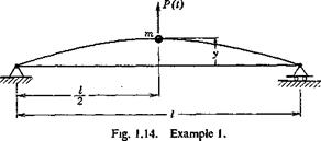
Example 1. A Weightless Beam with a Concentrated Mass at the Mid­span. Consider a weightless beam with a concentrated mass at the mid­

span (Fig. 1.14). A force P(t) acts on the mass. The geometrical con­figuration is determined completely by the displacement у of the mass m. Here

V = Ky Q — P(t)

GENERALIZED COORDINATES AND LAGRANGE’S EQUATIONS

where V is the strain energy. Substituting into Lagrange’s equation,

we obtain the equation of motion

my + Ky= P(t)

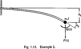
Example 2. A Weightless Cantilever Beam with a Mass, that Has a Finite Moment of Inertia, Attached at the Free End (Fig. 1.15). Let us take the displacement of m as qlt and the rotation of the mass moment of inertia /as q2-, then

T=mqf + lqf V = lKuqf + tKnqf + KM

where K{j are the stiffness-influence coefficients. Hence, from Lagrange’s equations, we obtain

GENERALIZED COORDINATES AND LAGRANGE’S EQUATIONS

Щі + Kn<h + Ki2% = p + Kn4i + кііЧі — Q

Подпись: 10 »=о
GENERALIZED COORDINATES AND LAGRANGE’S EQUATIONS

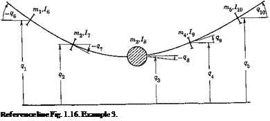
Example 3. An Airplane Idealized into a Weightless Elastic Beam Connecting a Number of Concentrated Masses and Moments of Inertia. Let us take the displacements of the masses and the rotations of the inertias as the generalized coordinates (as shown in Fig. 1.16). Then

ip ip

v = 2 2 (strain energy)

І=1 j—l

Подпись: Reference line Fig. 1.16. Example 3.

L = T — V

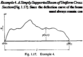
Подпись: Example 4. A Simply Supported Beam of Uniform Cross Section (Fig. 1.17). Since the deflection curve of the beam must always remain con

The equations of motion can be obtained from Lagrange’s equation. If the gravitational force need be considered, the gravitational potential should be added to V.

tinuous, it can be developed in a Fourier series. Thus the deflection w can be written as

CO

2

. П7ТХ

ansm —

71 = 1

The configuration of the beam is completely determined by the Fourier coefficients aw Hence, an may be taken as the generalized coordinates: q. = at (і = 1, 2, 3, • • •)

Подпись: (m = mass per unit length = const)  2

When the beam vibrates, w and hence q{ = a, are functions of time.

The strain energy is given by

dx

If there is a system of lateral loads acting on the beam, the generalized forces can be calculated as follows: Let the generalized coordinate an be given a virtual displacement dan. The beam configuration undergoes a virtual displacement 6w(x) = dan sin (mrx/l). The work done by the external loads p(x, t), the positive sense of which is defined as the same as that of w, is

Подпись:Qn <4, =jo pi*, 0 bw(x) dx = £ p(x,

But 6an is arbitrary; hence,

[l. mrx

Qn = Jo P(x> t) sm — dx

The equations of motion can then be written down according to Lagrange’s equation:

d /Щ dV dtdaj+dan Qn

i. e.,

T &n + "4a" =Jo p(~X’ ^ sin ~fdx (И = 1, 2, 3, • • •)

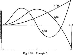
Example 5. A Cantilever Beam of Uniform Cross Section. The deflec­tion of the beam can be expanded into a series

CO

w(x, t) =^qn(t)fn(x)

GENERALIZED COORDINATES AND LAGRANGE’S EQUATIONS

П — 1

where f„(x) is the nth mode of the undamped free vibration of the beam (Fig. 1.18). The functions fjx) are orthogonal and can be normalized so that

/,(*) Ux) dx

Подпись: JoПодпись: Hence, following the same procedure as ao ^ M/V. when v = n, when v Ф n. in Ex. 4, we have

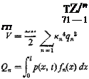
Подпись: TZ/" 71 — 1 ГТ1
г

where кп are the solutions of the equation cos кі – cosh к-/ + 1 = 0. There­fore, under a lateral load p(x, t) the equations of motion are

mlqn + ЕПкп% = f p(x, t)fn(x) dx Jo

ELEMENTARY AERODYNAMICS

A real fluid is viscous and compressible. But, if the speed of flow is much less than the speed of propagation of sound, the variation of density caused by the motion of a body in the flow is so small that the fluid may be regarded as incompressible. Furthermore, for fluids like water and air, the effects of viscosity are felt only in a thin layer (the boundary layer) next to the solid wall of the body. Outside the boundary layer the fluid may be regarded as nonviscous. A nonviscous and incompressible fluid is called a perfect fluid. In many problems of aeroelasticity, it is sufficient

to consider the fluid as a perfect fluid. However, there are cases in which the viscosity, however small, has profound effects, for it controls the boundary layer which may become detached from part of the solid body, and thus affects the macroscopic picture of the flow.

The force, exerted by the fluid on a body situated in a flow, does not depend on the absolute velocity of either the fluid or the body, but only on the relative velocity between them. The aerodynamic force consists of two components: the pressure force normal to the surface of the body, and the skin friction, or shearing force, tangential to the surface of the body. The latter is often negligible in aeroelastic problems.

In order to determine the parameters, on which depends the force that acts on a body situated in a flow, a dimensional analysis can be made. Obviously the force depends on the geometry of the body and its attitude relative to the flow; these, for geometrically similar bodies, can be characterized by a typical length / and a typical angle «. The force will also depend on the density of the fluid p, the viscosity of the fluid p, the speed of flow U, the compressibility of the fluid, and the nonstationary characteristics of the flow. The last item can be expressed in a clear-cut way if the conditions of flow happen to be periodic. In a periodic oscillation, the frequency со characterizes the nonstationary feature. The compressibility of the fluid may be expressed in various ways. A simple index of the compressibility is the speed of propagation of sound in the fluid, because sound is propagated as longitudinal elastic waves.

Let the speed of sound propagation be denoted by c. Then, in an oscillating flow of a compressible fluid, the force experienced by a solid body will depend on the following variables:

l, a, p, U, p, со, c

A dimensional analysis shows that, for geometrically similar bodies, the force F acting on the body can be expressed as

ELEMENTARY AERODYNAMICS(1)

where f is a function of the variables contained inside the parentheses. It is easy to verify that the parameters Ulpjp, toljU, and Ujc are all dimensionless numbers.

Подпись: p v

The following notations will be used throughout this book:

M = — = Mach number c

q = pVi— dynamic pressure

The parameters R, k, and M are named in honor of O. Reynolds, V. Strouhal, and E. Mach, respectively. The factor v = /лір is called the kinematic viscosity.

The speed of sound propagation in a gas is given by the equation

ELEMENTARY AERODYNAMICS

where p is the static pressure, p is the density, and у is the ratio of the specific heat at constant pressure to the specific heat at constant volume. For dry air, у = 1.4. Using the equation of state, we obtain

c=VyRJ

where Rg denotes the gas constant. For air, the above equation becomes

c = A9.WT

where T is in degrees Rankine. At the standard conditions at sea level, c = 1130 ft per sec.

For air under standard conditions of temperature and pressure: p — 0.002378 slug per ft3 at 15° C and 760 mm Hg v — 0.0001566 ft2 per sec at 15° C and 760 mm Hg

For water under the same conditions, v = 1.228 x 10⁻⁵ ft2 per sec. More complete data of the physical properties of air and water can be found in Refs. 1.51, and 2.25. For approximate mental calculation, the following formulas may be useful:

Dynamic pressure at sea level:

ELEMENTARY AERODYNAMICS

Reynolds number in air at sea level:

R = 10,000 (U in mph) (/ in ft)

In aeroelasticity we are concerned primarily with two components of force and one component of moment that act on a body. These are:

Lift — L — force perpendicular to the direction of motion

Drag = D — force in the direction of motion, positive when the force acts in the downstream direction

Pitching moment = M — moment about an axis perpendicular to both the direction of motion and the lift vector, positive when it tends to raise the leading edge of the body

When airplane wings or complete airplanes are considered, the mean chord c of the wing is usually taken as the characteristic length, and the wing area S the characteristic area. The three primary airplane coefficients are:

CL = lift/(<p§) = lift coefficient

CD = drag/(ipS) = drag coefficient (3)

Су = pitching moment/qSc — pitching-moment coefficient

CL, CD, and CM are functions of the Reynolds number, Mach number, Strouhal number, and the body’s shape and attitude with respect to the flow. For an airfoil, the attitude is described by the angle between the direction of motion U and a reference axis called the chord line. This angle, denoted by a, is called the angle of attack.

In a steady flow of an incompressible fluid, the Strouhal number and the Mach number both vanish, and CL, CD, Су depend on R and a alone. In the remainder of this section, unless mentioned otherwise, we shall consider only the steady, incompressible case.

The variation of the coefficients CL, CD, and CM with a is illustrated for a typical airfoil in Fig. 1.11. When a is small, CL increases linearly with a. The proportional constant is called the lift-curve slope and is denoted by a. When a becomes larger, the lift curve begins to level off and finally drops downward. The wing is then said to have stalled. The lift-curve slope a is nearly independent of the Reynolds number.

Let v be the fluid velocity at any point along a closed path of integration, dl an element of length along the path, and в the angle between v and dl. Then the circulation Г around the given path is defined as the line integral of v cos в:

Г = § v cos в dl (4)

The fundamental importance of the concept of circulation may be roughly stated by the fact that, in a perfect fluid, with constant total pressure and in steady motion, the circulation is identical around every simple closed path enclosing a given set of solid bodies. Thus the circulation around a body has a unique and well-defined meaning, independent of the choice

-24 -16 -8 0 8 16 24 32

ELEMENTARY AERODYNAMICS

Section angle of attack, a, degrees

Fig. 1.11. Lift and moment characteristics for the NACA 23012 airfoil. The moment is taken about a point located at V4-chord length behind the leading edge. The aerodynamic center location is computed from CL and CMrti data. The Reynolds number is seen to affect mainly the maximum lift coefficient. (From Abbott, von Doenhoff, and Stivers, NACA Rept. 824. Courtesy of the NACA.)

that may be made of the particular path used for calculating the value of the circulation.

A type of singularity in a fluid called a vertex line is a curve around which the circulation is a constant. A vortex line cannot end itself in a fluid; it must either form a closed’curve or extend to infinity, or else end on a free surface or a solid boundary. A free vortex, one on which no external force acts, is transported with the fluid; i. e., it moves with the flow. On the other hand, a bound vortex, one that moves relative to the flow, requires the action of external forces to maintain such relative motion. As mentioned before, in a steady flow, the circulation about a solid body is a constant. For a steady, two-dimensional flow of a perfect fluid about an infinitely long cylindrical body of any cross sectional shape whatever, the following can be proved theoretically:

(a) The drag is zero.

(b) In the absence of circulation around the body, the lift is zero.

(c) If there is a circulation of magnitude Г around the body, and if the body moves with a rectilinear velocity U relative to the fluid at infinity, then a lift exists, whose magnitude per unit length perpendicular to the flow is given by Joukowsky’s theorem:

L = PUY (5)

where p is the density of the fluid. The direction of the lift is normal both to the velocity U and the axis of the cylinder.

It is clear that, as far as the lift is concerned, the solid body may be replaced by a bound vortex line. For an unstalled airfoil, the circulation Г around it varies linearly with the angle of attack a. If a is measured from the zero-lift attitude which corresponds to Г = 0, then Г ~ L ~ a, and the lift coefficient can be expressed as

CL == a0 a (6)

The angle of attack thus measured is called the absolute angle of attack. The word “absolute” is sometimes omitted. It is understood throughout this book that, when we speak of an angle of attack, we mean the absolute angle of attack. If a is measured in radians (1 radian = 57.3°), hydro – dynamic theory gives the lift-curve slope

a0 = 2я – (theory, incompressible fluid) (7)

for thin airfoils in a two-dimensional flow. Experimental values of the lift-curve slope may be expressed in the form

a0 = 2ttij (8)

The correction factor rj is called the airfoil efficiency factor, which is less
than 1 («a 0.9) for conventional airfoil sections, but is greater than 1 for NACA low-drag sections.

According to the theory of thin airfoils in a two-dimensional incom­pressible fluid, the center of pressure of the additional lift due to change of a is located at V4-chord aft of the leading edge. This point is called the aerodynamic center. If the moment coefficient is computed about the aerodynamic center, it does not vary with CL. The symbol Сш or CMcti is used to denote the moment coefficient referred to an axis located at the V4-chord point. The aerodynamic center remains close to the 1/4-chord point in a compressible fluid as long as the flow is subsonic, but it moves close to the mid-chord point if the flow is entirely supersonic.

Подпись: D

The subscript 0 of the lift-curve slope a0 signifies that a0 is the value pertaining to an airfoil of infinitely long span. For wings of finite span

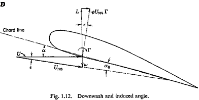
the lift-curve slope is smaller. In Prandtl’s finite-wing theory, a wing is replaced by a vortex line. Since a vortex line cannot end at the wing tip, it must continue laterally out of the wing and become a free vortex (trailing vortex) in the fluid. The vertical velocity w induced by the trailing vortices is called the induced velocity. Because of the induced velocity, the direction of flow at the airfoil is changed by an amount e, which is given by the relation

tan e = w/U (9)

From Fig. 1.12 it is seen that the effective angle of attack a,, is smaller than the geometric angle of attack a. Assuming that w is infinitesimal compared with U, we may write

The resultant force р[/гевГ acts in a direction normal to the resultant

velocity vector Ures. It can be resolved into a lift component L perpen­dicular to the velocity of flow U and a drag component (induced drag) D in the direction of U. Prandtl assumes that the circulation Г is pro­portional to the effective angle of attack a„. By using Eq. 6 relating CL (and hence Г) with a0, and expressing the downwash w in terms of the spanwise-lift distribution, a relation between the lift coefficient CL and the geometrical angle of attack a can be derived.

ELEMENTARY AERODYNAMICS ELEMENTARY AERODYNAMICS Подпись: (H) (12) (13)

The final result takes a particularly simple form if the wing planform is an elongated ellipse and is untwisted (having a constant angle of attack across the span). In this case the lift distribution across the span is elliptical, with a principal axis at the mid-span. The special properties associated with the elliptic lift distribution are that (1) the downwash is constant across the span, and (2) for a given total lift, span, and speed of flow the induced drag has its lowest possible value. For an elliptic lift distribution,

From the relations

Подпись: (14)CL = a0 a,, = aa.

and Eq. 10, one obtains the lift-curve slope of a wing of finite span:

a — ——– °° —■■ (elliptic lift distribution) (15)

1 + (a0/vJR)

For nonelliptic lift distribution, the downwash is no longer constant across the span. Equation 15 is modified as follows:

a = ———- —, ———- (nonelliptic) (16)

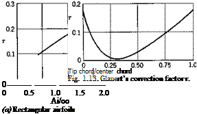
1 + (aJvJRX 1 + r)

where t is a small correction factor depending on the deviation of the lift distribution from the ideal elliptical form. Figure 1.13 shows the value of t as calculated by Glauert for straight-tapered, untwisted wings of aspect ratio Ж = 2тг. JRe is the effective aspect ratio. If the lift is symmetrically distributed over the span, JRe is given by Eq. 12. If the
lift is antisymmetrically distributed over the span (as induced by an anti- symmetrical deflection of the ailerons), with zero lift at the mid-span, then Re should be taken as half of the actual JR. Hence,

JRe = JR (for symmetrical lift distribution)

JRe = JR/2 (for antisymmetrical lift distribution) (17)

ELEMENTARY AERODYNAMICS

Such a correction of aspect ratio is necessary because Eq. 16 is derived for an untwisted wing. The correction (Eq. 17) is plausible, because each of the two halves of the antisymmetrical lift distribution appears similar to an elliptic distribution with a span equal to half of the actual wing span.

(b) Tapered airfoils with Л1 = oq (= 2ir)

Some important characteristic quantities of airfoils, such as the profile drag coefficient C/x>> the maximum lift coefficient CL max, the moment coefficient at zero lift Сш, the angle of zero lift are only of minor importance in aeroelasticity. They do not appear in most of the problems. On the other hand, the question of spanwise lift distribution corresponding to a twisted airfoil is of great importance in aeroelasticity. For mathe­matical simplicity, we shall often use the so-called strip theory as a first approximation. In this, one assumes that the local lift coefficient Сг(у) is proportional to the local geometric angle of attack a(y):

CM = aa.{y) (18)

The effect of finite span is then to be corrected by using a value of a corrected for aspect ratio.[3]

Finally, the principle of superposition must be mentioned. In aero­dynamics, the fundamental equations are essentially nonlinear, and so the superposition principle is valid only in special cases. However, in the airfoil theory, it is often assumed that the disturbance in the flow due to the presence of an airfoil is infinitesimal; i. e., the velocity induced by the solid body is infinitesimal in comparison with the speed of the undisturbed flow, and the hydrodynamic equations can be linearized. In this case the superposition is permissible.

THE INFLUENCE COEFFICIENTS AND INFLUENCE FUNCTIONS

In aeroelasticity, the most concise description of the elastic property of a structure is obtained by means of influence functions. If the structure is perfectly elastic, meaning that its load-deflection relationship is linear and that it returns to the initial configuration after all the loads are re­moved, then the influence functions can be uniquely determined. In most of the problems discussed below, not only the material elements of the structure are assumed to be elastic (subject to stresses below the pro­portional limit), but the entire structure also must be supposed to remain elastic. In judging the elasticity of the structure, we must specify the range of loads to be considered in a given problem. For example, consider an aircraft wing of sheet-metal construction. When the air load gradually increases, certain structural members may become buckled and go out of action. But the wing may remain elastic for a range of additional loads, even though the rigidity of the wing changes before and after the buckling.

Consider a perfectly elastic structure, rigidly supported,[2] and subjected to a set of forces Qv Q2, ■ • • Qn at points 1, 2, • • •, n respectively.

According to Hooke’s law, the deflection q1 at the point 1, due to the set of forces {Qi} may be written as

4i ~ anQi + Яігбг + ’ ‘ ‘ + ainQn (la)

The proportional constants au, a12 • • • are independent of the forces Qi> Qi, ’ • Qn- Similarly, the deflections at points 2, 3, • • •, etc., are

= а2ібі + aaQi + • • • + a2nQn (16)

qn — aniQi + an2.Qi + • • • + a„nQn

If the summation convention is used, the above equations may be expressed simply either as

П

qt =2««e,- O’ == l, 2, • • •, n) (2)

3 = 1

or as

qi auQi 0»y “ 0 2, • • ■, n) (3)

For a rigidly supported perfectly elastic body, the elastic deformation is a unique function of the forces acting on the body. For, if there exists a different set of deflections q, q2, • • •, q’n, corresponding to the same Qi> Qi,’ ‘ ’> Qn, we may first apply the loads Qv • ■ ■, Qn to deform the body into qlt q2, • • ■, qn at points 1, 2, • • •, n; then apply the loads — Qi, — Qi, ■ • – Qn t0 Obtain deflections – q, – q’2, ■ ■ •, – q’n

at points 1,2,- • •, n. The final configuration has deflections q1 — q, qi — q’i, • ■ •, qn — q’n at the specified points. But the external loads are now completely removed; it follows from the definition of perfect elasticity that qi—q, qi~q’i, etc., must all vanish; i. e., q1 = q, q2 = q’2, etc. Hence a contradiction is obtained, and we must conclude that q{ and Q{ are in one-to-one correspondence.

The uniqueness of the force-deflection relationship implies not only that the constants a{j are unique functions of the elastic body (because atj may be interpreted as the deflection at point і due to a unit load acting at pointy), but also that the set of Eqs. 3 can be solved for Q} and that the solution is unique:

П

Qi Kijqj (/ = 1,2, • • •, n) (4)

In other words, the determinants |aM| and Ki} do not vanish.

The constants ai} and Ku are called, respectively, flexibility-influence coefficients and stiffness-influence coefficients. The flexibility-influence coefficients are generally called simply influence coefficients.

The physical interpretation of a stiffness-influence coefficient K{j is the force that is required to act at the point і due to a unit deflection at the point j, while all points other than j are held fixed.* In the case of a single degree of freedom, the stiffness-influence coefficient is the familiar spring constant.

It is often convenient to regard Eqs. 3 and 4 as matrix equations, {<jrj, {Qt} being column matrices and {%}, {K(j} being square matrices (§ 3.6). We have shown that {a{j}, {AT„} are nonsingular and that they are the inverse of each other.

When a set of forces is applied to an elastic body, work is done by the forces. Let us define a displacement corresponding to a force as the component of the displacement under the point of application of the force and in the direction of the force. If Дqx corresponds to Qv the work done by Q1 through a displacement Дq1 is equal to Q1 Aqv

Let qx, q2,■ • qn denote the displacements corresponding to the forces Qi> C?2> ‘ ‘ •> Qn which act at the points 1, 2, • • •, n, respectively. If all the forces are applied very slowly so that equilibrium is maintained at all times, the total work done by the forces will be

w = f dqx + f "fi, dq2 + • • • + P’e„ dqn (5)

Jo Jo Jo

The evaluation of the integrals in Eq. 5 is extremely simple if the ratios Qx-Q2. • • • : Qn are maintained while the absolute values of the forces gradually increase. In this case Q( is proportional to q{. Writing Qi = K{qu we have

П П

w= У Я<Кф dqt=y Ktq* (6)

i = 1 г=1

— Qn in a different order, one will be able to extract energy from the elastic body, in violation of the principle of conservation of energy.

Подпись: or Подпись: (7) (8)
THE INFLUENCE COEFFICIENTS AND INFLUENCE FUNCTIONS

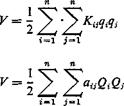
Thus the total work done is independent of the manner in which the final configuration is reached. This work is stored in the body in the form of elastic strain, and is called the strain energy. By using Eqs. 3 and 4, the strain energy V (numerically equal to W) may be written as

where Ki} and atj now refer to “corresponding” forces and displacements.

If we now load the body first by a force Qx at point 1 and then a force Q2 at point 2, the strain energy may be written as

у = khiQi + K62a + Qi&izQz) (9)

If the order of application of Qx and Q2 is reversed, we have

V — ifl22 Qz + Kft2 + Qz(aziQi) (10)

In order that Eqs. 9 and 10 represent the same quantity for arbitrary values of Qx, Q2, we must have

aiz = azi (11)

The same argument can be applied to any pair of forces and the corres­ponding displacements to show that the flexibility-influence coefficients are symmetric; i. e.,

Подпись:Similarly,

Подпись: Hence, Подпись: 3V 3q/ THE INFLUENCE COEFFICIENTS AND INFLUENCE FUNCTIONS

Castigliano’s theorem can be derived from Eqs. 7 and 8. Differentiating Eq. 7 with respect to qit we obtain

SEC. 1.4 Similarly,


dV

THE INFLUENCE COEFFICIENTS AND INFLUENCE FUNCTIONS


(15)


Equation 15 states that, if the strain energy is expressed as a quadratic function of the loading, then its partial derivative with respect to the load at a point gives the corresponding deflection at that point. Similar statement can be made for Eq. 14.

Подпись:The above results can be generalized in several directions. First, let us consider a three-dimensional body subjected to a system of forces. Let a system of rectangular Cartesian coordinates be chosen so that a displace­ment u, resolved in the direction of coordinate axes, has components (tq, w2, m3), and a force F the components (Fv F2, F3). Letfff r, £)d£ drjd’C be the rth component of the force acting over an element of volume dg dr] di at the point (f, r, 0, /,(£, rj, 0 being a force density. Then in analogy with Eq. 2, we may write the rth component of the displacement u at the point (x, y, z):

where the integration is taken over the entire volume of the elastic body. The function Gij(x, y, z; f, rj, 0 is the influence function of the displace­ment at (x, y, z) due to a force at (f, rj, 0. a and f being vectors, Gifx, y, z; f, rj, 0 is a tensor of rank 2 in a 3-dimensional Euclidean space.

The expressions for strain energy can be obtained in analogy with Eqs. 7 and 8. For example,

Подпись: з з – 5 t]> f) jifl У) ~)

f(f, v, QdxdydzdUridi (17)

THE INFLUENCE COEFFICIENTS AND INFLUENCE FUNCTIONS

Furthermore, the symmetry argument can be generalized to show that

In other words, the influence functions are symmetrical: The rth component of displacement at x due to theyth component of a unit force at у is equal to the yth component of displacement at у due to the rth component of a unit force at x. This is the reciprocal theorem of Maxwell and of Betti and Rayleigh.

In practical applications, the external forces acting on an elastic body often “take the form of concentrated forces and moments. In such cases the linear and angular displacements under the points of application and

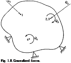
Подпись: Fig. 1.8. Generalized forces.

in the direction of the forces and moments are of particular interest. It is convenient to define a generalized force as either a concentrated force or a couple, and, correspondingly, a generalized displacement as either a linear or an angular displacement. A concentrated couple can be regarded as the limiting case of two equal and opposite forces approaching each other but maintaining a constant moment. The extension of the above results to cover the generalized forces and displacements is obvious. The notation can be simplified as follows: Let Q{ and q( denote, respec­tively, the generalized force and the generalized displacement at the point

Подпись: n Подпись: (/= 1,2,- • ■, n) Подпись: (19)

/.* Q refers to either a force or a couple; q refers to either a linear or an angular displacement. Then

The constants c(j are called the influence coefficients of the (generalized) displacement at і due to a unit (generalized) force at j. The inverse of the {c,7} matrix defines the stiffness-influence coefficients {ЛГ,7} in the generalized sense.

The symmetry property (Eq. 12, 13, or 18) can be generalized to show that, if c(j relates the corresponding generalized displacements and forces, then

cH = cH, Ka = KH (i, j = 1, 2, • ■ n) (20)

It is very important to notice the word “corresponding” in the statement

* As shown in Fig. 1.8, a force and a couple acting at the same point may be counted on as two generalized forces, indicated by two different subscripts.

of the reciprocal relations. A generalized force corresponds to a general­ized displacement if their product gives exactly the work done. Thus, for a beam, the change of slope corresponds to a moment, the deflection corresponds to a force, and the twisting angle corresponds to a torque. Although Maxwell’s reciprocal relation asserts that the deflection at Px due to a unit couple at P2 is equal to the rotation at Рг due to a unit force at Pv it is completely wrong to assert that the rotation at P1 due to a unit force at P2 must be equal to the rotation at P2 due to a unit force at Pv In the latter case the force and rotation do not correspond to each other.

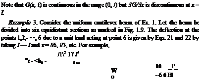
Examples of Influence Functions and Influence Coefficients. The influence coefficients, being displacements under a unit load acting at some point on the structure, may be determined experimentally or com­puted according to the principles of elasticity. There are many efficient methods of calculating the elastic displacements. The reader is referred to books on the theory of structures. A few examples will be given below:

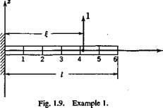
Example 1. A Cantilever Beam Clamped at x = 0 (Fig. 1.9). Let the stiffness El be a constant, and let the load and displacement be both

THE INFLUENCE COEFFICIENTS AND INFLUENCE FUNCTIONS

parallel to the z axis; so the indices i, j in Eq. 16 are both 3 and can be omitted. The influence function is given by the deflection curve under a unit load at x = f.

… „ „ . d2w M 1 _

(,)For o £*<;{<;/,

Therefore

w = G(x, i)=-^I( 3£-x) (21)

/ dw

(Й) For 0 < £ < a; < /, w = w(£) + y — j (x — f) w = G(x, £) = -¥-( 3z – І)

Note that G(x, f), dGjdx, and Э2(7/Эа:2 are continuous throughout the range (0, /) but d3Gjdx3 is discontinuous at the point x = f.


Example 2. A Beam of Torsional Rigidity GJ Subject to a Torsional Moment (Fig. 1.10). The differential equation is


THE INFLUENCE COEFFICIENTS AND INFLUENCE FUNCTIONS

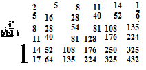
In this way the entire matrix of flexibility-influence coefficients may be obtained:


THE INFLUENCE COEFFICIENTS AND INFLUENCE FUNCTIONS

An inversion of the matrix {cf gives the stiffness-influence coefficients {*■«}•

( 3.1384 1565 – 1.9844 5597 0.7994 0766

– 1.9844 5597 2.4455 9557 – 1.7979 2676

0. 7994 0766 – 1.7979 2676 2.3923 0068

– 0.2131 7531 0.7461 1348 – 1.7712 8020

0. 0532 9384 – 0.1865 2846 0.6928 2076

Подпись:

Подпись: - 0.2131 7531 0. 7461 1348 - 1.7712 8020 2.3390 0970 - 1.5847 5411 0. 4307 9176 Подпись: 0. 0532 9384 -0.1865 2846 0. 6928 2076 - 1.5847 5411 1.6461 9015 - 0.6076 9728 Подпись: - 0.0088 8231 0. 0310 8807 -0.1154 7008 0. 4307 9176 - 0.6076 9728 0. 2679 4926

– 0.0088 8231 0.0310 8807 – 0.1154 7008

If a desk calculator is used, the inversion can be best done by Crout’s method (see footnote in § 3.6, p. 102). The matrix {Ktj}, as given in Eq. 26, carries more significant figures than its numerical accuracy warrants from the physical point of view, but it is given here for arithmetic reasons. If one wishes to verify that the product {ATw}{cy} gives the unit matrix up to six significant figures, it is imperative to carry at least eight significant figures in the process of computation.

The determinant of the matrix {c„} is

Ы = 1.330 244 X 10-9 (^-J6 (27)

Its numerical smallness is caused by the near proportionality of the deflec­tion modes when the points of application of two unit loads are close to each other. (Compare, for example, the last two columns of {cfJ} in Eq. 25.) Thus, although сц never vanishes, the inversion of {ct}} may become difficult as more stations are taken across the span.