Category An Introduction to THE THEORY OF. AEROELASTICITY

THE ELASTIC AXIS

In the preceding Section, the shear center of a straight, cylindrical beam is defined. Since the analysis is based on St. Venant’s theory of bending and torsion, the exact boundary conditions at the ends of the beam cannot always be satisfied. The shear center so defined is a section property. For each cross-sectional shape, there associates a shear-center location.

The concept of shear center can be extended to a curved beam. One imagines that, at any point on the beam axis, a cylinder tangent to the given beam, and having the same normal cross section, is prescribed. The shear center of this cylinder is then taken as the shear center of the curved beam at that point.

The locus of shear centers of the cross sections of a beam is called the elastic axis of that beam.[1] The elastic axis is a natural reference line in describing the elastic deformation of the beam; for the resulting differ­ential equations are the simplest.

By using the elastic axis as defined above, it is possible to derive the classical Bernoulli-Euler equations of bending for a curved beam in analogy with Eq. 1 of § 1.1. The theory of a curved beam whose elastic axis coincides with the centroidal axis of the beam has been developed completely in Chapter 18, § 289 of Love’s book.12 If the shear centers do not coincide with the centroids of the cross sections, it is necessary to define a set of local coordinate axes parallel to the generalized principal torsion-flexure axes defined by Love, but with the origin located at the shear center. The “torsion” and curvature of the elastic axis can then be determined in the same manner as those of the centroidal axis, and the relation between the bending moments and torque and the change of curvatures and “torsion” at a section can be derived. The resulting equations are useful for “thin” beams, the cross-sectional dimensions of which are, by definition, much smaller than the radius of curvature of the beam.

The practical application of the elastic axis to aircraft structures is, however, subject to severe limitations. Owing to the effects of sweep angle, shear lag, restrained torsion, cutouts, buckling of skin panels, etc., the shear center often cannot be defined without ambiguity. In other words, the concepts of shear center and elastic axis lose their simplicity or usefulness when a structure other than a simple cylindrical beam is con­sidered. In any case of doubt, it is better to use influence functions which describe the deformation pattern of the structure due to a unit load acting on the structure. An influence function is a well-defined quantity. It can be measured on an existing structure, and it may be calculated by refined structural theories in special cases.

In the present book, the elastic axis will be used only when it is a straight line and is associated with a structure that behaves like a simple beam.

THE ELASTIC AXIS

In engineering literature, the terms flexural center, center of twist, and flexural line are often used. They are defined as follows: Consider a

p

Fig. 1.7. Flexural center of a cantilever beam.

cantilever beam of uniform cross section. If a load P is applied at a point A on the free end (see Fig. 1.7), the section АС В will rotate counter­clockwise in its own plane. If P is applied at It, the section АС В will rotate clockwise. Somewhere between A and В is a point (say C) at which the load P can be applied without causing rotation of the section АС В in its own plane. This point is called the flexural center of the section ACB.

More generally, for a slender, curved, cantilever beam, the flexural center of a cross section is defined as a point in that section, at which a shear force can be applied without producing a rotation of that section in its own plane. Closely associated is the center of twist which is a point in a cross section that remains stationary when a torque is applied in that section. If the supporting constraint of the beam is perfectly rigid, the flexural center coincides with the center of twist. (See Ref. 1.15, or p. 29 of Ref. 1.9.) It is important to notice that these definitions are referred to particular sections. For example, when a force is applied at the flexural center of a section, that section will not rotate; but, unless the beam is homogeneous, cylindrical, and clamped in a plane normal to its
axis, other sections of the beam may rotate. In other words, whether other sections of the beam rotate or not is irrelevant to the definition of a flexural center. This fact makes the locus of flexural centers useless except when it is a straight line; then it coincides with the elastic axis.

For a given loading, a flexural line is defined as a curve on which that loading may be applied, so that there results no twist at any section of the beam. In general, different load distributions correspond to different flexural lines, and there exist load distributions that do not have a flexural line. A simple example is a concentrated load acting on a curved beam. This property renders the flexural line useless in aeroelasticity except in the simplest cases.

SHEAR CENTER

Consider a straight thin-walled beam of uniform cross section, which is subjected to a shearing force S as shown in Fig. 1.1. Let a set of ortho­gonal Cartesian coordinates xyz be chosen as shown in the figure, where

SHEAR CENTER

Fig. 1.1. Equilibrium of forces acting on an element of a thin-walled section.

the z axis is parallel to the axis of the beam, and the x and у axes are the principal axes of the cross section. Let us assume that at any point in the cross section, the stress distribution over the wall thickness is uniform. It is convenient to introduce a curvilinear coordinate s along the circum­ferential direction of the cross section, and to speak of the “shear flow,” meaning the shearing force per unit of circumference

q = rt (1)

where r is the shearing stress, and t is the thickness of the wall. The equation of equilibrium of the forces in the axial direction acting on a small element of area ds dz is, according to the diagram on the right-hand side of Fig. 1.1, where oz denotes the axial stress :

(az + dz) t ds — ozt ds + | r + ) t dz — rt dz = 0 (2)

Passing to the limit ds, dz -> 0, one obtains

Подпись: t
Подпись: Эq + S“° Подпись: (4)

or, multiplying by the thickness t, if it is constant,

SHEAR CENTER

Thus the shear flow q depends on the rate of change of the axial stress az. A few simple cases will be considered below.

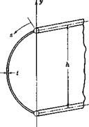
(a) Flat Shear Webs. A flat “shear web” is one that is subjected to pure shear; i. e., it is defined by the condition az = 0. Such a web is approx­imated by the one shown in Fig. 1.2. In this case, Eq. 4 implies that

q — const

(5)

The constant is easily evaluated from statics:

S

q = h

(6)

where S is the total shear force over a section, and h is the height of the web»

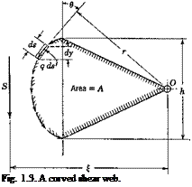
(b) Curved Shear Webs. According to Eq. 4, the condition q = const prevails also for a “curved shear web,” over which az = 0. As shown in Fig. 1.3, the shear flow follows the curvature of the cross section. The resultant force in the у direction is

S = J q cos в ds (7)

where в is the angle between the vector of the shear flow q and the у axis, and the integration is taken over the entire section. Obviously

S — § q dy — q h j (8)

(9)

SHEAR CENTER

Подпись: or

which is the same as Eq. 5. The shear flow is equal to the total shear force divided by the height of the beam.

Подпись: Fig. 1.3. A curved shear web.
SHEAR CENTER

It is important to find the location of the resultant shear. For this purpose the moment about a point О in the plane of the cross section

produced by the shear flow may be computed. Let r be the perpendicular distance from 0 to the tangent at s where q acts. From Fig. 1.3 the moment about 0 is

M0 = $qrds (10)

Since q is a constant, this may be written as

M0 = q §r ds = 2qA (11)

where A is the area of a sector enclosed between the cm /ed shear web and two radius vectors with origin at 0 as shown in the figure. But this moment is also equal to the resultant shear S times its moment arm £ about the origin 0,

Подпись: 2A ~h
Подпись: (12)
SHEAR CENTER
Подпись: Hence, from Eqs. 9 and 11,

M0 = S£

It can be easily verified that the spatial location of the line of action of the resultant shear is independent of the location of the origin 0.

The web of a two-flange type of beam approximates in practice the

shear web described above. Such a beam can transmit a shear force, but only if the forge is applied at the location specified by Eq. 12 and parallel to the plane of the two flanges, as shown in Fig. 1.3. If it is applied along any other line of action, it will cause an unbalanced twisting moment that the beam alone cannot resist.

(c) Open Thin-Walled Sections. In general, the axial stress az does not vanish when the beam is subjected to a transverse loading. In many cases, however, it is sufficiently accurate to use the elementary beam formula for a bending moment M due to the transverse loading

Подпись:Подпись: ctz = —My I

where у is the distance from the neutral plane, provided that the у axis is a principal axis of the cross section, and that the shear load vector is parallel to the у axis. Hence,

Подпись: (14)Эогг _ у dM у

?z I dz I

in accordance with Eq. 3 of § 1.1. If we assume again that the shearing stress is uniformly distributed over the wall thickness, the shear flow is — obtained from Eq. 4 by an integration:

where q0 is the value of q at j0. Using Eq. 14, one obtains

S P

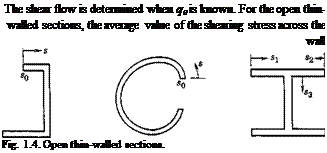
Подпись: The shear flow is determined when q0 is known. For the open thin- walled sections, the average value of the shearing stress across the wall Fig. 1.4. Open thin-walled sections.

q = % – 7 Je2/? ds (15)

thickness vanishes at the ends of the section, in accordance with St. Venant’s theory of torsion. Hence, if s0 is taken as one of the ends, then q0 — 0. This is illustrated in Fig. 1.4.

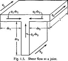
In the last case of Fig. 1.4, there is a junction where three members meet. Let qx, q2, q3 be the shear flow toward the junction in the three members, respectively; then a condition of equilibrium is

This can be seen from the free-body diagram of a small element at the junction as shown in Fig. 1.5. Equation 16 represents the condition of equilibrium of the forces in the axial direction.

SHEAR CENTER

For a multi-flanged beam, the material concentrated at the flanges resists the bending moment (Fig. 1.6). Equation 15 can be modified to give the change of shear flow across each of the flanges. Let ДA be the

SHEAR CENTER

area of a flange, then the difference of q on the two sides of the flange is

Aq = — ~yAA (17)

The equations given above are sufficient to determine the shear flow in any open thin-walled section. When q is known, the resultant force is
given by Eq. 7, and the resultant moment about the origin О is given by Eq. 10. The location of the line of action of the resultant shear is there­fore at a distance £ from the origin:

SHEAR CENTER(18)

where the symbols r, s, and у have the same meaning as shown in Fig. 1.3, and the integral is taken over the entire cross section. The shear flow q is, in general, a function of s and cannot be taken outside of the integral.

Similar calculation can be made if a shear acts in the direction of the other principal axis of the beam cross section. The distance from the origin, г], of the line of action of the resultant shear which is parallel to x axis, can be determined by an expression similar to Eq. 18. The inter­section of these two lines of action, the point with coordinates £, r referred to a set of centroidal principal axis, is called the shear center of the cross section. Since an arbitrary shear load can be resolved into components parallel to the two principal directions, it becomes evident that, if a shear vector acts through the shear center of the cross section, the bending stress distribution will be given by the elementary beam formula, and no twisting of the beam will occur. This is the significance of the shear center.

If the resultant shear does not pass through the shear center, it can be resolved into a shear of equal magnitude that does pass through the shear center and cause torsionless bending, and a couple that will cause twisting.

(d) Closed Thin-Walled Sections and Solid Sections. The equations derived in the previous paragraph apply as well to closed thin-walled sections, except that it is now no longer evident that there exists a point s0 at which q0 vanishes. The exact values of q depend on the line of action of the resultant shear force.

It is convenient to define the shear center as a point through’ which acts a shear force that will produce a “pure” or “torsion-free” bending. The beam subjected to a shear force that acts through the shear center will be “torsion-free.” A shear force that acts in a line that does not pass through the shear center will cause both bending and torsion.

The analytical formulation of the above definition depends, however, on the precise meaning of the term “pure bending” or “torsion-free bending.” Based on the classical theories of bending and torsion, several different but equally convincing definitions have been proposed for “pure bending.” A detailed discussion is presented in Appendix I, which covers also solid sections and thick-walled sections. For a given definition of the term “pure bending,” a corresponding location of the shear center can be computed. Fortunately, shear-center positions of airplane structures

based on various definitions differ very little from each other, and in practical applications any one of these definitions may be used.

It may be noted that the shear-center locations calculated in previous paragraphs under cases b and c are in agreement with the definition just given. No ambiguity exists for the concept of torsion-free bending in an open thin-walled section. This clear-cut feature is a result of the assump­tion that the shearing stress is distributed uniformly over the thickness of the section.

ELEMENTARY BEAM THEORY

Consider a cylindrical beam of uniform isotropic material. In each cross section of the beam, two mutually perpendicular principal axes, passing through the centroid of the cross section, can be determined, about which the second moments (the moments of inertia) of the beam cross-sectional area assume stationary values with respect to rotation of the centroidal axes, and the product of inertia of the area vanishes. The plane containing one of the principal axes of all cross sections is called a
principal plane. If the beam is acted on by a bending moment M in a principal plane, the beam will deflect in that plane. Let 1 /R represent the change of curvature of the beam in that plane; then, within the elastic limit of the beam,

Подпись:R~ El

ELEMENTARY BEAM THEORY Подпись: (2)

where E is Young’s modulus of the material, and I is the moment of inertia* of the beam cross section about a principal axis perpendicular to the principal plane in which M acts. Let у denote the distance from the neutral plane; then the bending stress is given by

Equations 1 and 2 are applicable, approximately, also to a straight beam with nonuniform cross sections subjected to distributed external loads, provided that E, I, 1 /R, and M are the local values and that the variation of the beam cross section is gradual. They are, however, not directly applicable to curved beams.

Equations 1 and 2 are derived under the assumptions that the displace­ment of the beam is small, that the Hooke’s law between stress and strain holds, and that the plane cross sections of the beam remain plane during deformation. They are referred to as engineering beam formulas.

ELEMENTARY BEAM THEORY ELEMENTARY BEAM THEORY Подпись: (3)

When a system of external forces acts on a beam, it produces shear and bending moment in the beam. The loading (lateral force per unit length) p, the shear S, and the moment M are connected by the equations

where x denotes distance measured along the axis of the beam. For a given beam, after a given direction has been chosen for the coordinate x, the signs (i. e., the positive senses) of p, S, and M may be consistently chosen by verifying Eqs. 3.

If a twisting moment whose vector is parallel to the beam axis is applied on the beam, the cross sections will rotate about the beam elastic axis.

* For semimonocoque thin-walled box beams part of the skin may be buckled under a compressive stress. The contribution of such buckled panels to the bending stiffness can be accounted for by reducing the actual width of the skin panels to their "effective width.” In this case the factor / in Eq. 1 is the "effective” moment of inertia, computed on the basis of the effective width of skin.1-3

The rate of change of the angle of twist в (radians) along the length of the beam is given by the formula

Подпись: (4)d6_T_ dx ~ GJ

where T is the twisting moment about the shear center of a section at x, and GJ denotes the torsional rigidity. G is the shear modulus of rigidity, but У stands for the quantities as shown in Table 1.1, according to various cross sections.1-27

In Eq. 4, the positive sense of the vector 0 is chosen as that of the co­ordinate axis x. However, the positive sense of the torque T, like that of the shearing stresses, cannot be determined until the positive side of the surface on which the torque acts has been chosen. The sign convention is as follows: Consider a beam element of length dx, which is bounded on both ends by normal cross sections of the beam. Let normal vectors of the cross sections be drawn from inside of the element, (the so-called outer normals). If a torque T acting on the end of the beam element agrees in its vector sense with that of the outer normal, then Г is positive; otherwise it is negative.

If the beam is subjected to a system of distributed twisting moment of intensity m per unit length, then the twisting moment T is variable across the span. Let us define m as positive if its vector sense agrees with that of x, which we shall assume to be pointing to the right. Then on an element of length dx, there acts a torque — T on the left-hand side, a torque T + dT on‘the right-hand side, and a torque m dx on the element. (See Fig 1.21 on p. 48.) Thus the condition of equilibrium of the element demands that

Подпись: dT dx Подпись: — m Подпись: (5)

— T + m dx + T dT = 0 or

ELEMENTARY BEAM THEORY

Combining Eqs. 4 and 5, we obtain the following relation for a beam subjected to a system of distributed twisting moments:

In engineering beam theory, the beam deflection is assumed to be infinitesimal. Let w be the deflection of the beam; then, approximately,

1 d2w M ~R ~ dx2 ~ ~El

Table 1.1


Beam Cross Section


Circular cylinder


Polar moment of inertia = — (t/1 — rf,4)


Aa2b2
4(й2 + Ь2У


ELEMENTARY BEAM THEORY

T Elliptic cylinder


40TP (aPProx-)


Ip = polar moment of inertia about centroid


Rectangular section


T


A?

‘з ’


A = area of cross section


Я


Single-bay thin – walled tube


A — area enclosed by tube walls


^ Гд2(Иі2 аіг(^і ^г)2 ~Ь ДрИг
L йоійіг + йігвго + агоат


Double-bay thin – walled tube


where aiS —


the integral being taken


along boundary between A{ and A}.


ELEMENTARY BEAM THEORYELEMENTARY BEAM THEORYELEMENTARY BEAM THEORYELEMENTARY BEAM THEORYELEMENTARY BEAM THEORYELEMENTARY BEAM THEORYELEMENTARY BEAM THEORY

When a positive sense is chosen for w, the positive sense of M must be checked against Eq. 6. Such a check of signs should always be made in order to avoid confusion in the calculations.

From Eqs. 3 and 6, we obtain

ELEMENTARY BEAM THEORY

where w is the deflection and p is the loading per-unit length acting on the beam. The positive senses of w and p agree with each other.

When the external forces acting on the beam do not lie in a principal plane, the forces should be resolved into components lying in each of the two principal planes. The deflection of the beam can then be computed in these two planes separately and then added vectorially. Similarly, if an external couple acting on the beam is inclined to the beam axis, the couple should be resolved into a bending moment and a twisting moment, and the induced displacements computed separately.

In solid beams, the deflection is essentially induced by the bending moments. The deflection caused by the shear 8 can be neglected. But in thin-walled box beams the shear deflection can become quite important, particularly in calculating the higher-order vibration frequencies and modes.184

Accompanying the application of external load on the beam, elastic strain energy is stored in the beam. For a solid beam the strain energy due to transverse shear stresses is usually negligible in comparison with that due to bending and torsion. If the deflection w(x) and the torque T(x) are measured at the shear center of a section at x, then the strain energy can be written as

ELEMENTARY BEAM THEORY

where l is the length of the beam. For thin-walled structures, the strain energy due to transverse shear is not negligible. A term of the following form,

V=l-[ K{x)Sx)dx (9)

2 Jo

should be added, where K(x) is a function of the cross-sectional shape and the material of the structure.

The elementary theories of torsion and bending are based on assump­tions that are usually violated in actual aircraft wing structures. The elementary torsion theory is valid for a shell of constant cross section, subjected to a torque at each end in the form of a shear flow that is distributed in the section in accordance with the theory, and that leaves the end sections free to warp out of their original planes. An actual wing has a variable section and is subjected to distributed torque loads; as a result, the tendency to warp, in general, differs from section to section, and secondary stresses are set up by the resulting interference effects. The normal stresses so induced are called the “bending stresses due to torsion.” Similarly, the elementary bending theory is strictly valid if the applied load is a pure bending moment. In actual wing structures, the bending moments are produced by transverse loads, and, in general, the shear strains in the beam produced by these loads violate the assumption that plane cross sections remain plane. As in the torsion case, inter­ference effects between adjacent sections may produce secondary stresses. In the particular case of thin-walled box beams, the effect of the shear strain on the distribution of normal stresses is called the “shear lag.”

A general theory of bending and torsion of beams of variable cross sections, subject to a variable loading, is very complicated. A practical solution exists for thin-walled cylinders under the assumption that cross – sectional shape of the cylinders is maintained by diaphragms, which are infinitely rigid against deformation in their own planes but are perfectly flexible for deflection normal to their planes. For box beams of closed sections the effect of shear lag is important with respect to the stress distri­bution, but is insignificant with respect to the deflection of the beam except for swept wings. This is because the deviations of the stresses from those predicted by the elementary theories are local, and local disturbances are smoothed out by the integration process necessary to calculate deflections. The deviations of the deflections from those predicted by the elementary theories are therefore much smaller than the stress deviations. For this reason adequate accuracy can often be achieved for the deflection (and the influence-coefficient.) calculations, even when highly simplified theories are used. On the other hand, the effect of shear lag and restrained warp­ing is very large for thin-walled structures with open cross sections (the portion of a wing with a large cutout may be regarded as open sections). See articles listed in the bibliography at the end of this chapter for the treatment of special problems. See, in particular, Ref. 1.70.

In applying the results of the elementary beam theory to airplane structures, considerable engineering judgment is often necessary because the effects of cutouts, shear lag, differential bending of the spars, dis­continuous changes of section properties, etc., must be properly accounted for. Occasionally a wing or a tail cannot at all be considered as a “beam” or a “torque tube.” In such cases a more comprehensive analysis of the elastic deformation is necessary. In aeroelasticity the most convenient scheme of describing the elastic properties of a structure is to specify its influence functions. The calculation of the influence functions for a structure other than a simple beam may be very difficult, but it is a prerequisite for aeroelastic analyses.

PRELIMINARIES

The discussion of aeroelasticity requires certain preliminary information on the theory of elasticity, aerodynamics, and mechanical vibrations. There exist a number of excellent textbooks on these subjects. Therefore we shall review only briefly some of the fundamental facts in this chapter and explain the notations and sign conventions that will be used in the text.

The reader is urged, however, to read carefully §§ 1.2 and 1.3, concerning the definitions of shear center, elastic axis, flexural line, etc., because these terms have been used somewhat ambiguously in the engineering literature. In § 1.4 the influence functions are explained, and in § 1.6 the generalized coordinates and Lagrange’s equations are reviewed and illustrated by several examples. These subjects must be understood thoroughly.

Throughout this book a vector will be printed in boldface type, as, for instance, a velocity vector v, a force vector F. A vector in a three – dimensional space has three components, which are indicated by sub­scripts. Thus a force F referred to a system of rectangular Cartesian coordinates x, y, z has three components Fx, Fy, Fz, Sometimes it is more convenient to label the xyz coordinates as x1x2xs coordinates and to indicate Fx as Fu Fy as F2, Fz as F3. The vector F, being specified by the three components F1; F2, F3, may also be identified simply by writing F{ (j = 1, 2, 3).

A relation among several vectors may be expressed either by a single vector equation or by a system of equations expressing the relations among the components of the vector. For example, let a (with components ax, a2, a3) be the acceleration of a particle, m its mass, and F (with com­ponents Fx, F2, F3) the force acting on the particle. Then Newton’s law of motion for this particle can be written either as

F = m&

0)

Fx — таг

F2 = ma2

(2)

F3 = ma3

Equations 2 may be shortened into the following form Fi = ma{ (i = 1, 2, 3)

We shall consider Eqs. 1 and 3 as entirely equivalent expressions.

This notation will be extended to tensor equations and matrix equations by means of multiple subscripts.

PRELIMINARIES Подпись: (4)

One of the most important simplifying conventions in all mathematics is the summation convention: to use the repetition of an index to indicate a summation over the total range of that index. For example, if the range of the index і is 1 to 5, then

If at = a and bt = b are two vectors, the product аф{ is the scalar product of a and b:

Подпись: (5)Подпись: (6)Подпись:a • b = a fit

As another example, if i, j = 1, 2, 3, then з

CijFj = ‘^CljFj = CUF1 + C12F2 + C13F3

i=i

з

F’ijFj =■ ‘^fC3jFj = C3Fl + ад + ад

3

F’SjFj ~ ‘^’CqFj ~ С31Р, + C32F2 + ^33F3

3 = 1

The system of Eqs. 6 may be simply written as

з

ад = lt 2> 3)

3=1

This summation convention will be used in this book.

the effect of aerodynamic forces

Aeroelasticity is the study of the effect of aerodynamic forces on elastic bodies.

The classical theory of elasticity deals with the stress and deformation of an elastic body under prescribed external forces or displacements. The external loading acting on the body is, in general, independent of the deformation of the body. It is usually assumed that the deformation is small and does not substantially affect the action of external forces. In such a case we often neglect the changes in dimensions of the body and base our calculations on the initial shape. Even in problems of bending and buckling of columns, plates, or shells, either the external loading or the boundary constraints are considered as prescribed. The situation is different, however, in most significant problems of aeroelasticity. The aerodynamic forces depend critically on the attitude of the body relative to the flow. The elastic deformation plays an important role in deter­mining the external loading itself. The magnitude of the aerodynamic force is not known until the elastic deformation is determined. In general, therefore, the external load is not known until the problem is solved.

One of the interesting problems in aeroelasticity is the stability (or rather instability) of a structure in wind. Since, for a given configuration of the elastic body, the aerodynamic force increases rapidly with the wind speed, while the elastic stiffness is independent of the wind, there may exist a critical wind speed at which the structure becomes unstable. Such instability may cause excessive deformations, and may lead to the destruction of the structure.

A major problem is the flutter of structures such as airplanes or suspen­sion bridges, when small disturbances of an incidental nature induce more or less violent oscillations. It is characterized by the interplay of aero­dynamic, elastic, and inertia forces, and is called a problem of dynamic aeroelastic instability. The particular case of an oscillation with zero frequency, in which in general the inertia force may be neglected, is called the steady-state, or static, aeroelastic instability.

Quite different from the above are the response problems in which the response of an aeroelastic system to an externally applied load is to be found. The external load may be caused by a deformation of the elastic body, such as a displacement of the control surfaces of an airplane, or by disturbances such as gusts, landing impacts, or turbulences in the flow.

The response to be found may be the displacement, the motion, or the stress state induced in the elastic body. Again the response problems may be classified into the steady-state or static problems, in which the inertia forces may be neglected, and the dynamic problems, in which the aerodynamic, elastic, and inertia forces all enter into the picture.

There is a close relationship between the stability problems and the response problems. Mathematically, most stability problems can be des­cribed by a system of homogeneous equations, which are satisfied by a trivial solution of zero displacement (or zero motion), meaning that nothing happens at all. On the other hand, a response problem is repre­sented by a nonhomogeneous system; i. e., the initial conditions and the external forces are such as to cause the governing equations to be non­homogeneous, and to admit a solution not vanishing identically. A response problem generally associates with a stability problem. As an example, consider the response of an airplane wing to atmospheric turbu­lences. We can formulate the problem of flutter by asking the following questions: Is there a critical speed of flight at which the airplane structure becomes exceedingly sensitive to the atmospheric turbulence; i. e., does there exist a speed at which the structure may have a motion of finite amplitude, even in the limiting case of an atmospheric turbulence of zero intensity? This is equivalent to the following formulation which is usually made in flutter analysis: Is there a critical speed at which the aeroelastic system becomes neutrally stable, at which motion of the struc­ture is possible without any external excitation? Thus the response of an airplane structure to atmospheric turbulence and the flutter problem are linked together. When the response of the structure to a finite disturbance is finite, the structure is stable, and flutter will not occur. When the structure flutters at a critical speed of flow, its response to a finite disturb­ance becomes indefinite.

This alternative theorem is true in practically all corresponding response and stability problems. Either the homogeneous system has a nontrivial solution while the corresponding nonhomogeneous system has no solution, or the nonhomogeneous system has a solution while the corresponding homogeneous system has no solution other than the trivial one.* It is thus proper to discuss the response and stability problems together as two phases of the same phenomenon.

There exists, however, a very important distinction between the response and stability problems, in regard to the justification of the linearization process often used in the mathematical formulation of a physical problem.

* In exceptional cases both the nonhomogeneous and the corresponding homogene­ous system may have a solution. But such exceptions ordinarily have little engineering significance.

In the stability problems, the amplitude of the elastic deformation is indeterminate, and only the modes of deformation (not their absolute magnitude) are of interest; hence, it is logical to consider the elastic deformation as infinitesimal in the neighborhood of an equilibrium state. Therefore the small deflection theory in elasticity and aerodynamics is applicable, and linearization of the governing equations can be justified. On the other hand* the absolute magnitudes of the deformation and stress in a structure are of primary interest in the response problems. Hence, it is necessary to consider finite deformations. As the fundamental equa­tions of fluid and solid mechanics are often nonlinear, it is necessary to consider the effects of nonlinearity, whenever the response reaches a finite amplitude. Thus the justification of linearization of the fundamental equations is always open to question.

Of course it is desirable to treat the nonlinear equations per se, but the mathematical difficulties are generally insurmountable. Generally we are forced to linearize, in order to reach a practical solution. Then it must always be remembered that the justification of the linearization remains to be shown.

In this book, attention will be directed mainly to the stability problems, not because the response problems are less important, but because they are well-known in engineering philosophy. On the other hand, the stability aspect of aeroelasticity is novel.

Generally speaking, aeroelasticity includes the study of all structures in a flow. But those problems in which the elastic deformation plays no significant role in the determination of the external loading will not be discussed in this book. For example, the problem of the distribution of wind load on a building will be excluded.

A survey of the field of aeroelasticity is given in Chapters 1 through 11. Important problems are discussed from the physical point of view. The chief aim is to provide an elementary treatment of the basic problems and to point out the essential parameters involved in their solution. The aerodynamic problems are discussed in greater details in Chapters 12 through 15.

An Introduction to THE THEORY OF. AEROELASTICITY

The previous volumes of the GALCIT * series have included two on aerodynamics and two on structural analysis and elasticity. The pres­ent work combines elements from these two fields. The subject of aeroelasticity has received a rapidly increasing amount of attention dur­ing the past few years, and the recent literature has become very volu­minous. However, practically all of the contributions to this literature have been in the form of scientific or technical papers dealing with spe­cific problems. Very few books dealing with the subject as a whole have appeared, and it is believed that a work of this type would now be useful, even though the subject is still expanding rapidly. The present volume has been prepared with this in mind, and it is hoped that it will prove valuable both in connection with academic instruction and also to scientists and engineers working in the field.

Clark B. Millikan For the Editors

May 1955

* Guggenheim Aeronautical Laboratory, California Institute of Technology.

Trees sway in the wind; so may smokestacks. Flags and sails flutter; so may airplane wings and suspension bridges. The wind played an­cient aeolian harps; so it plays the electric transmission lines, making them “sing” or even “gallop.” These, and other phenomena that reveal the effect of aerodynamic forces on elastic bodies form the subject matter of aeroelasticity. It is a subject of growing importance in many fields of engineering, particularly in aeronautics, where, in the last dec­ade or so, with the ever-increasing aircraft size and speed, aeroelasticity has become one of the most important considerations in aircraft design.

Although aeroelastic phenomena occur in everyday life, the attempts to develop a theory toward their understanding were made essentially by aeronautical engineers. A serious study of aeroelasticity started in the early ’20’s and, at present, it is still a young science making rapid progress. Nevertheless, part of the theory has reached a classical stage, and a general treatment is now possible.

This book owes its existence to a course on aeroelasticity which has been given to students in aeronautics at the California Institute of Tech­nology since 1948. It is intended primarily as a textbook, but it should be useful also to designers and flutter engineers, for h gives a composite picture of various aspects of aeroelastic problems.

As the subject relies so heavily on aerodynamics, elasticity, and me­chanical vibrations, most of the fundamental concepts in these related branches of mechanics are briefly explained in Chapter 1. Those hav­ing a rudimentary knowledge of aerodynamics and strength of material should have no difficulty in reading it. In this brief review, an effort is made to stress a number of points of importance in aeroelasticity, such as the arbitrariness contained in the usual definitions of shear center, the meaning of elastic axis, the conditions under which influence coefficients are unsymmetrical, the spanwise phase shift in the torsional vibration of a cantilever beam with viscous damping. However, no attempt is made to present, in a detailed manner, all the methods of analyzing the elastic deformation of complicated structures, or their natural vibration modes. The basic reason is a desire to move as quickly as possible to the main topics of aeroelasticity, to bring out aeroelasticity’s main features in

contrast to those usually found in treatises on aerodynamics, elasticity, and mechanical vibrations.

The main body of the text is divided into two parts. Chapters 2 to 11 contain a survey of aeroelastic problems, their historical back­ground, basic physical concepts, and the principles of analysis. Chap­ters 12 to 15 contain the fundamentals of oscillating airfoil theory, and a brief summary of experimental results.

The selection of material perhaps requires some explanation. In Chapter 2, some problems of common occurrence in civil and mechani­cal engineering are outlined.. The main character of these problems is that the structures concerned are not streamlined and are unamenable to theoretical treatment. One must rely chiefly on experimental results to understand the nature of aerodynamic forces. A wide variety of phenomena is described. These phenomena are likely to appear also in aeronautical engineering when unfavorable conditions are encoun­tered, such as when a wing is stalled, or when it is situated in a turbulent flow. An understanding of these phenomena not only is important in itself but also provides a natural background for the linearized theory to be discussed in the following chapters.

Principal problems of aeronautical interest are developed in Chap­ters 3 to 11. The steady-state problems and flutter theory are treated along conventional lines. But in discussing the dynamic stresses in air­craft due to gusts or other dynamic loading, as well as buffeting and stall flutter, the statistical aspects are emphasized. I believe that some statistical concepts and techniques are of vital importance to a proper understanding of many dynamic-stress problems.

The theory of aeroelasticity is concluded in Chapter 11 with a gen­eral formulation and a brief discussion of the basic mathematical char­acteristics. It is hoped that this discussion will attract the attention of mathematicians toward the important field of non-self-adjoint equations, which, owing to certain inherent difficulties, are very much neglected in the mathematical literature. Although in the past most of the prac­tically important problems in physics were governed by self-adjoint equations, it is now shown that the entire field of aeroelasticity would have to be based on non-self-adjoint equations. In aeroelasticity those problems that are reducible to self-adjoint systems are really excep­tional. Thus, a new impetus exists for the study of non-self-adjoint equations.

The aerodynamics of oscillating airfoils presented in Chapters 12 to 15 is of an introductory nature, and includes only those topics that are required in reading this book. Many aspects of the unsteady airfoil theory are still undergoing rapid development, and it seems yet too early to give a complete account.

As this book is not intended to be a compendium or a handbook, at­tention is directed only to the fundamental principles. The physical assumptions involved in the mathematical formulation of a problem are always emphasized, so that the degree of approximation relative to the real physical system can be seen. In this way the reader will realize the directions in which future improvement may lie.

In order to limit the size of the book, I have refrained from going into detailed discussions on such topics as flight-flutter testing, control and stability of aircraft, swept-wing analysis, stochastic theory of buffet­ing, and applications of digital and analog computing machines. An attempt is made, however, to provide sufficient guidance to the existing literature, so that the reader may find proper references to the particular subjects of his own interest.

The list of references in this book is by no means complete. Only those that are believed to be readily accessible to the general reader are quoted. Papers published expressly for limited circulations are gen­erally omitted. A few important papers appeared too late to be in­cluded in the bibliography. But the reader can easily obtain the most recent references from the journal Applied Mechanics Reviews.

In preparation of this book, I am indebted to many of my colleagues at the California Institute of Technology. The constant advice of Pro­fessor E. E. Sechler is gratefully acknowledged. Doctors H. Dixon, A. Kaplan, A. Roshko, W. H. Wittrick, С. M. Cheng, Y. J. Wu, and Professors M. L. Williams and G. Housner read part of the manuscript and offered many valuable comments. Mrs. Dorothy Eaton, Mrs. Betty Wood, Mrs. Virginia Boughton, Mrs. Virginia Sloan, and Mrs. Gerry Van Gieson helped the preparation of the manuscript. To them and to many other friends I wish to express my sincere thanks. To Dr.-Ing. H. Drescher of the Max-Planck Institute I am especially grate­ful for permitting me to use some illustrations from his research work. My wife, Luna Yu, helped in reading the manuscript and proofs, check­ing the equations, and working out examples. I have derived infinite encouragement from her enthusiasm and patience in working on this book.

This book is dedicated to the memory of my father.

Y. C. Fung

Pasadena

May 1955

CONTENTS

Introduction 1

1. Preliminaries 4

2. Some Aeroelastic Problems in Civil and Mechanical Engineering 60

3. Divergence of a Lifting Surface 81

4. Steady-State Aeroelastic Problems in General 113

5. Flutter Phenomenon 160

6. Fundamentals of Flutter Analysis 186

7. Engineering Flutter Analysis and Structural Design 246

8. Transient Loads, Gusts 272

9. Buffeting and Stall Flutter 310

10. Applications of Laplace Transformation 333

11. General Formulation of Aeroelastic Problems 365

12. Fundamentals of Nonstationary Airfoil Theory 381

13. Oscillating Airfoils in Two-Dimensional Incompressible Flow 395

14. Oscillating Airfoils in Two-Dimensional Compressible Flow 418

15. Unsteady Motions in General. Experiments. 444

Appendixes 471

Author Index 483

Subject Index 491

Aeroelasticity deals with the combined features of fluid mechanics and solid mechanics. Aircraft designers are concerned with aerodynamic performance of an elastic aircraft. Designers of bridges and skyscrapers need to know what the wind will be doing to their structures. Designers of artificial heart valves and students of medicine want to know how blood flows in very flexible vessels. Naturalists and environmentalists are inter­ested in the locomotion of birds, fish, and mammals, or the swaying of trees and fluttering of leaves. Scientific study of these problems has to focus on flow in regions with deformable boundaries, and on the deformation of solids subjected to fluid loading, which varies with the deformation itself. The dynamics of these systems are often intricate, surprising, and important for the survival of man, machine, animals, and plants. I was involved in each of these areas at different periods of my life.

I entered college at the time of World War II and chose to study aeronautics because it seemed to be a topic relevant to national survival. After graduation I worked in the Chinese Institute of Aeronautical Research in Chengdu. One of my assignments was the preparation of a design manual of the control surfaces, and in that job I read about flutter. Then I received a scholarship and entered the California Institute of Technology in Pasadena. When my mentor, Professor Ernest Sechler, asked me what I would like to work on for my Ph. D. thesis, I said flutter. Dr. Sechler said that our Dr. Theodor von Karman used to have a research project on the flutter of suspension bridges sponsored by the State of Washington Bureau of Highways and Bridges after the wind-driven failure of the Tacoma Narrows Bridge. The cause of the failure was believed to be the von Karman vortex street. When Dr. von Karman retired, Dr. Maurice A. Biot took over the project. When Dr. Biot went back to Belgium, Dr. Louis Dunn continued in this research. But Dr. Dunn went to the Jet Propulsion Laboratory. “We have a wind tunnel built specially for the testing of suspension bridges. See what you can do with it.” So I played with models in that wind tunnel, focused on airplanes, and wrote my thesis, which was expanded later and became this book.

Then came the jets and spacecraft. I worked on flutter, control, wind and gust load, clear-air turbulence, stability and fatigue of aircraft structures,

fuel sloshing in space vehicles, landing impact, and ground shocks. I earned consulting fees on the analysis of wind load on the cantilevered roof of the University of Washington stadium in Seattle, and on methods to damp out wind-generated vibrations of a restaurant suspended under two arches at the Los Angeles Airport. By the 1960s, my interest was shifted to biomechanics. In 1966, I resigned my post at Caltech and went to the University of California at San Diego to start a bioengineering program in the School of Medicine. Many research problems in biomechanics are aeroelastic in nature. Indeed, at a meeting of the American Society of Zoologists, I found many zoologists are familiar with this book on aeroelasticity because it is a convenient reference for the non-stationary wing theory. For readers who are interested in biological applications of aeroelasticity, may I offer the following three books written by Y. C. Fung, and published by Springer-Verlag, New York: Biomechanics: Mechanical Properties of Living Tissues, 1st ed., 1981, 2nd ed., 1993. Biodynamics: Circulation, 1984. Biomechanics: Motion, Flow, Stress, and Growth, 1990. Also, the following book may be helpful: Y. C. Fung, A First Course in Continuum Mechanics, for Physical and Biological Engineers and Scien­tists, Prentice Hall, Englewood Cliffs, New Jersey, 3rd ed., 1993.

Y. C. Fung, La Jolla