Category An Introduction to THE THEORY OF. AEROELASTICITY

THE STRUCTURAL OPERATOR

The structural operator gives the elastic deformation of a structure under a system of external forces. If the structure is perfectly elastic, so that Hooke’s law applies, the structural operator can be concisely ex­pressed in terms of influence functions.

A real material deviates from Hooke’s law and shows anelastic or inelastic behavior to some extent. As an important case, let us assume that the fundamental relation between stress and strain is linear, buf depends not only on the instantaneous values of stress and strain, but also on the rate of change of stress and strain.

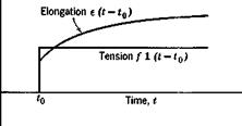
Under the linearity assumption, no permanent set remains after the removal of all stresses. To derive an expression relating the force and deformation, let us consider a simple bar which is initially free from stress. At an instant of time t0 let a tensile force /be suddenly applied and then maintained for t > ,f0. The corresponding elongation of the bar, (the indicial admittance) can be expressed in the following form:

e(t — t0) = [K + (/>(t — t0)]f for t > t0

= 0 for /</„ (1)

where A" is a constant and <f>(t — t0) is a function of time. This is repre­sented in Fig. 11.7. The function <j>(t — t0) is generally so chosen that lim ф(/ — t0) = 0. Then К represents the limiting value of the elongation

t—> 00

є under unit tension after the transient effect is damped out. The function

THE STRUCTURAL OPERATOR

Fig. П.7. Indicial response of a rod subject to tension.

Фи — to) is sometimes called a “deformation function.” Note that, if Hooke’s law holds, фи — t0) = 0.

Since the stress-strain relation is linear, the principle of superposition is applicable. The response of the bar to an arbitrary loading//) can be obtained by the Duhamel integral

Ф) = KfU) + Ґ Фи – to) dto (2)

J— 00 dlQ

This result may be generalized to a three-dimensional body to show that the effect of anelasticity on the elastic deformation may be expressed by a tensor of generalized deformation function.

Anelasticity is revealed by the damping characteristics of an engineering structure (see Zener11-5). If f(t) represent a cyclicly varying force, Eq. 2 will indicate a hysteresis loop the area of which represents the dissipation of energy, and is a measure of the internal friction of the material. For a harmonic motion, a linear material has an elliptic hysteresis loop.

The internal friction may become nonlinear and depend on the life history of a material if the stress level is sufficiently high. Experiments show that the energy dissipated per cycle when a body is subjected to cyclic stresses varies with the number of cycles it has been subjected. This

phenomenon was observed in 1865 by Lord Kelvin11-2 and was called the “fatigue of elasticity.” There seems to exist a mechanism by which a metal can remember its experience, can show fatique by overworking and re­covery by resting. For example, a mild steel at room temperature sub­jected to a cyclic stress whose extreme values lie below 80 per cent of the endurance limit shows little change of internal friction, whereas the same steel subjected to repeated stresses between this value and the endurance limit will cause an increase of internal friction as much as 25 times that of the initial value in the annealed condition (see Lazan11-3). Cyclic stresses above the endurance limit have more pronounced effects.

For built-up structures, energy dissipation may result from play in the riveted joints, from relative motion in the cracks of welding, or from the hinges of movable parts. The damping force may behave either as a viscous fluid or as dry friction, and generally depends on the amplitude of the motion. There are indications that, for built-up beams, the non­linear component of the load-deflection curve contains mainly a second- power term, and the energy loss per cycle varies approximately as the third power of the amplitude of vibration.111,11,4

Since aeroelasticity concerns built-up structures, and yet the definitive laws of damping are unknown, more careful experiments would have to be performed in order to isolate the effect of the various parameters involved. However, for metal airplanes of conventional design, the internal friction is stnall. It may be assumed that the effect of internal friction is revealed essentially through the energy it dissipates, rather than the exact form of the stress-deformation relationship. Under this assumption we may replace the real material by a linear solid with the stipulation that the corresponding energy dissipated per cycle be the same.

In airplane structures, the elastic buckling of the sheet metal is always an important factor. As the region of buckling develops when the stress level (or the load factor) increases, the load-deflection relationship becomes a function of the load. In some oscillation problems, the amplitude of oscillation can be regarded as infinitesimal, and a correct solution can be obtained by evaluating the effective influence function at the steady-state load factor. In response problems the nonlinearity cannot always be overlooked.

NATURE OF THE OPERATORS IN AEROELASTICITY

As an aeroelastic system may be composed of a large number of electrical, hydraulic, mechanical, as well as aerodynamic elements, it is evident that the operators involved are much varied. From the point of view of analysis, it is convenient to classify the operators into two kinds: (1) those relating quantities that are essentially independent of the space coordinates, such as an electric voltage across two terminals, and (2) those relating quantities that are functions of space, such as the elastic displace­ments of an airplane. In operators of the second kind, space integrals are generally involved. Control-system operators, mechanical, electric,

or hydraulic, are generally of the first kind, while aerodynamic, structural, and inertia operators are generally of the second kind.

For example, a simple resistor and capacitator network as shown in Fig. 11.6 is governed by the following equation:

d

The interested variables V1 and V2 are essentially independent of the space coordinates. More complicated networks can be built up by such elementary ones. The resulting relations between the input and output can be expressed as ordinary linear differential equations. The analysis of such a system presents little difficulty in principle. The design of a satisfactory system to perform a specified function, (the so-called synthesis problem) of course is more difficult.[33]

On the other hand, the inertia force, aerodynamic force, and elastic deformation, being functions of both space and time, must be governed either by partial differential equations or by integral equations.

In the following sections, the structural and aerodynamic operators occurring in aeroelasticity will be considered. The inertia operator describes inertia forces. In airplane dynamics, it is convenient to use a system of reference coordinates attached to the airplane, and thus moving with respect to an “inertial” frame of reference. The expres­sion of the inertia operator referring to moving axes can be quite com­plicated, but it has been treated exhaustively in books of theoretical mechanics. f The case of small disturbances from a steady symmetric motion is of particular importance. The inertia operator can be linear­ized under the assumption that the square and higher-order products of the small disturbances (linear and angular velocities, as well as the elastic displacements) are negligible in comparison with the disturbances themselves.

THE FUNCTIONAL OPERATORS AND THEIR ALGEBRA

The functional diagrams can be represented algebraically by operators. Let a functional block that converts an “input” Qt into an “output” B0 (Fig. 11.5) be written symbolically as

eB = o e{ (1)

The symbol О is called an operator, and the process of finding B0 from 6( is called an operation on Bt by the operator O. It is to be noted that B„

and may represent quantities of different physical dimensions, for example, Bt an angle, and B0 a force. The physical dimensions of an operator are determined by the dimensions of B0 and B{.

If it is possible to solve the inverse problem of finding the input from a known output, then we say that an inverse of the operator exists, and write

в0 = О 6{, 6( = O-i B0 (2)

If there exists a one-to-one correspondence between Qt and B0 for all allowable B(, the operator is said to be regular* Otherwise it is singular. A regular operator has a unique inverse. In the examples named above, the operator that transforms the angle of attack into lift is regular in ranges of flow speed that excludes the critical-divergence speeds, and is singular at the critical-divergence speeds. Similarly, the operator that transforms the gust into the wing response is regular when the speed of flow is not a flutter speed, and is singular at flutter speeds. In. aero – elasticity, we generally consider regular operators that become singular only at certain special values of a set of parameters (e. g., the dynamic

* Clearly it is necessary to specify the regions in which the quantities 0,- and в0 are considered. However, the explicit statements of the regions of interest in our examples below are generally omitted in favor of conciseness. For example, if the linearized airfoil theory is used, the angle of attack, the downwash, and the lift force, etc., must be small. But the range of applicability of the linearized theory will not be mentioned every time. It is hoped that this lack of rigor will not cause confusion.

pressure, the reduced frequency). The set of parameters at which an operator becomes singular are eigenvalues of that operator. The deter­minations of the response from a regular operator and the eigenvalues of a singular operator are the two main problems in aeroelasticity.

An operator is said to be linear if it has the following property:

0(^i + x2) = Oaq + Ox2 (3)

where x1 and x2 both belong to the region over which the operator О is defined. It is said to be nonlinear if this relation does not hold over the entire region of definition. For mathematical simplicity, only linear operators will be considered hereafter.

Modern mathematical theory of functional transformations can be applied to the functional operators to render the mathematical treatment exact. But for the present purpose a heuristic account will be sufficient.

The operators occurring in aeroelasticity may be algebraic, differential, integral, or integral-differential.* They will be discussed in greater detail later. First let us consider some of their algebraic properties.

Consider again the steady-state lift-distribution problem. Let us designate the operators by subscripts as defined by the following equations:

p = Oi(« + 9), 9 = 02p (4)

where p is the aerodynamic pressure distribution, a is the wing surface without elastic deformation, and 9 is the elastic deflection corresponding to p. Obviously we may consider 9 as being generated by two successive operations Oj and Oa and write the entire process in a single equation:

9 = 0201(a + 9) (5)

The successive operations 020j may be regarded as a single operation generated by Oa and Ox in the specified order. It is called a composition product of the original operators. Note that it is in general noncommuta- tive; i. e., 020г Ф 0X02. Strict attention must be given to the order in which a composition product is formed.

Let us assume that and 02 are both linear. Equation 4 can then be written as

p = Ога + Oj0

and

9 = 02p = 02(0га + OjO) = 020ja -f

* An element of a functional diagram may represent a single number, a continuous function, a matrix of numbers, or a matrix of continuous functions of space and time. In particular, the interpretation of the variables as matrices is very important. By such an interpretation the operational equations are made very concise.

OA(« + 0) – 02(V + OA0 (6)

Therefore the composition product of two linear operators is linear.

The lift distribution on the elastic wing as represented in Fig. 11.2 can then be characterized, under the linearity assumption, by the equation

0 = 020]a + О2ОХ0 or

0 — O2OX0 = 020ja

Let us write I as an identical operator, which transforms any quantity into itself:

10 = 0 (7)

The relation between 6 and a can then be written as

(I – OjOJfl = 020,a (8)

A formal solution of this equation is

0 = (I — 020j)_1 OjjOjoc (9)

where (I — 0,00 і 1S the inverse operator (assumed unique) of I — 020x. In order to interpret the meaning of the inverse operator (I — 020j)_1, let us develop the expression formally into a power series in 020x by means of the binomial theorem:

(і – oa)-1 = і + o2ox + (02ox)2 + (OA)3 + • • • (io)

where

(O A)2 = (0,00(020,)

(O, oo*+1 = (OAXOA)* (k = 2, з, • • •) (11)

Since 020j transforms an angle into an angle, so do all the successive powers of OA – Applying Eq. 10 to Eq. 9, we may write

Подпись: OD (12)

If the process can be justified, the solution 0 can be obtained by summing the infinite series.

The summation of the infinite series 12 actually amounts to a process of successive approximations. The first term gives the elastic deformation of the wing corresponding to the lift acting on a rigid wing. The second term gives the increment of the elastic deformation due to the change of

lift corresponding to the elastic deformation first computed. The third term gives the second increment of elastic deformation due to the lift corresponding to the first correction of the elastic deformation, and so on. Hence, in this particular case, the process 10 is justifiable for sufficiently small dynamic pressure of the flow. The series 12 is known to converge (Chapter 3) whenever the dynamic pressure q is less than

Example 1. The Lift Acting on a Two-Dimensional Airfoil {Fig. 11.2). Consider the two-dimensional case of § 3.1. Here

Ma — Lee = qc2ea(v. + 9)

Me = K9 = Ma

Hence,

Oj = qc2ea

o2 = 1 IK

THE FUNCTIONAL OPERATORS AND THEIR ALGEBRA Подпись: qc2ea K( - qc2eajK)

Equations 12 and 9 gives at once

The lift per unit span is given by

Подпись: qca a 1 — qc2ea/K L = qca(p. + 0) = in agreement with § 3.1.

Example 2. Divergence (Fig: 11.3). Here the functional relation is represented by

0^9 = 9

In the two-dimensional case (Ex. 1), we obtain at once the critical condition

4c’iea j = 0

К

which yields

_ JL

Чйіч ~ c2ea

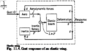
Example 3. Gust Loading (Fig. 11.4). Let the gust be represented by G and the other symbols denote quantities as shown in Fig. 11.4. Let the operators be defined as follows:

L — OloG + О Lq9 F= Oj9 9 = О e(L + F)

From the loops shown in Fig. 11.4, we obtain

Подпись:Oa[(0 loG + 0»9) + О70] = в
О® O^G = (I — ОЙО£0 — ОвО,) 0

в — (I — 0Е0Ев — О jjOjr)-1 OeOlgG

Example 4. Flutter. If G = 0, the last equation of Ex. 3 becomes a homogeneous one:

(I — ОЙО£0 — OjgOjr) 0 = 0 (13)

which gives the critical-flutter condition. (Divergence may be considered as flutter of zero frequency, and hence is included in the above equation.) Since Oe depends on the rigidity of the wing, while Oie depend on the dynamic pressure and the reduced frequency, the problem of flutter is to determine the eigenvalues of the rigidity, dynamic pressure, or reduced frequency at which Eq. 13 has a nontrivial solution.

FUNCTIONAL DIAGRAMS

In analyzing an aeroelastic system, it is convenient to distinguish the various functions that each element performs. Sometimes many elements together perform a single function, such as an electronic amplifier, which converts an input signal into another signal, but is composed of many resistors, capacitors, transformers, and vacuum tubes. Sometimes a single element performs several functions, such as an airplane wing, which produces lift force, elastic deformation, and inertia force. Whether several elements should be grouped together to be considered as a single

unit or a single element should be analyzed into several functional units depends on. the particular problem under consideration. But in all cases it is helpful to represent the entire system in a pictorial form so that the interaction among various elements can be clearly seen. Such pictorial representations are called functional diagrams. They are also called block diagrams if no single physical element is analyzed into several functional units.

The meaning of functional diagrams can be best illustrated by examples.

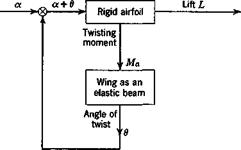
Lift of an Elastic Wing. If a change of angle of attack a (measured at the wing root) of a cantilever wing is regarded as an input, and the total

FTg. 11.1. Functional diagram of a wing.

lift force L acting on the wing as an output, the function of the wing may be represented symbolically as in Fig. 11.1. The relation between L and a, however, depends on the elastic deformation of the wing. It is convenient to consider the wing as composed of two elements: the wing as a lift-producing mechanism, and the wing as an elastic structure. With respect to aerodynamics, each configuration of the wing may be con­sidered as rigid. With respect to the elastic deformation, the action of

FUNCTIONAL DIAGRAMS

Fig. 11.2. An elastic wing.

aerodynamic forces is the same as any other system of exterior forces. The partial problems in aerodynamics and elasticity may be solved in the classical manner, but these two solutions must be properly combined to account for the behavior of an elastic wing. An elastic wing may be represented functionally as in Fig. 11.2. The airfoil, at an angle of attack a and having a deflection surface в, produces an aerodynamic pressure distribution p. The elastic wing, in response to the pressure distribution, produces a deflection surface в. Let us denote the wing surface corres­ponding to the initial angle of attack a also by the symbol a; then the

geometrical configuration may be simply written as a + 0, with respect to which the aerodynamic force is computed. Thus the rigid-airfoil-elastic – structure system forms a loop. It is a feedback system.

Wing Divergence. In the preceding example let a and 0 be so measured that L = 0 when a = 0 = 0. Then, in general, 0 = 0 is the only solution

JL Ma

FUNCTIONAL DIAGRAMS FUNCTIONAL DIAGRAMS

when a = 0. Let us now ask whether there exists a nontrivial solution 0 Ф 0 when a = 0 (Fig. 11.3). If such a solution exists, the wing is said to be critically divergent. In the critical divergent condition the amplitude of 0 is indeterminate. Since the system represented in Fig. 11.3 can be superposed on that in Fig. 11.2, it is clear that, at the critical-divergent condition, the lift problem has no unique solution. Conversely, when the

wing is nondivergent, the unique solution of Fig. 11.3 is 0 = 0, and the corresponding solution of Fig. 11.2 exists.

Gust Loading on an Airfoil. In dynamic problems the wing performs three distinct functions: It produces (1) aerodynamic force, (2) inertia force, (3) elastic deformation. It is convenient to represent the wing’s triple functions as three independent operators. In an example of the gust loading on a wing which is restrained against pitching, the functional diagram may be shown in Fig. 11.4.

Flutter is a companion problem. Instead of finding the response of
the wing to a gust, we ask whether the homogeneous system obtained by setting G = 0 in Fig. 11.4, has a nontrivial solution.

Again, as in the corresponding problems of lift and divergence, here the alternative theorem is: Either the homogeneous system has a nontrivial solution (flutter occurs), or the gust-response problem has a solution.

GENERAL FORMULATION OF AEROELASTIC. PROBLEMS

In the previous chapters several types of aeroelastic problems are treated. A large number of other problems can be formulated, the practical importance of which depends on the type of the structure and the conditions of the flow. In order to clarify the basic features of any problem, and to determine the degree of approximation of an analysis, it is desirable to have the formulation as general as possible at the beginning, and then to specialize in particular cases by introducing further assump­tions. In this way the relationship between various approaches to the problem can be understood, and, if an improvement on a known theory is desired, one can locate the restrictive assumptions and decide which one should be relaxed.

In § 11.1 the feedback nature of aeroelastic systems and their represen­tation by functional diagrams are considered. The functional operators concept is then introduced in § 11.2 to reduce the pictorial representations of functional diagrams into algebraic equations. The operators entering aeroelastic analysis are examined in greater detail in §§ 11.3 to 11.5.

Knowing the form of the operators involved, we will have no difficulty in writing down the governing equations according to the functional diagrams and the operational equations. The accuracy of the formulation of each problem is clearly indicated by the assumptions used in deriving the operators.

The mathematical characteristics of aeroelastic problems are briefly discussed in § 11.6.

FLUTTER

The method of Laplace transformation can be applied to study the stability of oscillating airfoils. Let us consider the motion of a two – dimensional flat-plate airfoil of unit span having two degrees of freedom h and a as considered in § 6.8. The equations of motion are given by Eqs.8,9 and 10 of § 6.8. The Laplace transformation of these equations can be obtained easily. Assuming that

Подпись:Подпись: (2)h — h = a = a = 0 when t = 0

we obtain

A(s)^{h/b} + = £Є{Р) /s2

Подпись: where, with the symbols y, xa, ra as defined on p. 216,

D{s)Se{hjb} + E(s)£e{v) = E£{Q) /s2

Подпись: 1 2 C(- is)FLUTTERB(s) — — yxa -(- ah

FLUTTER

s

The function C(— is)/s denotes the Laplace transform of the Wagner’s function Ф(т):

FLUTTER


A comparison of this equation with Eq. 6 of § 6.9 shows that C(— is) can be obtained from the Theodorsen’s function C(k) by replacing к by — is. From the form of Theodorsen’s function given in Eqs. 8, 8a, 8b of § 6.9, it is clear that C(k) as a function of the complex variable к is analytic in the entire upper half-plane, including the real axis. Correspondingly C(— is) is analytic for the right half-plane R1 j > 0. In other words, if we put ik = s, then the expressions of lift and moment given in Eqs. 9 of § 6.9 hold for a divergent oscillation e3T, (R1 j > 0). The validity of this generalization has been discussed by W. P. Jones15’80 and Van de Vooren in his discussion of Ref. 15.26.

The solution of Eq. 2 may be written as*

FLUTTER(5)

where

Д11 — E, Д]д — В, Д si — D, Д22 — A (6)

AO) = A(s) B(s)

D(s) E(s)

The functions ДО), ДпО), • • •, Д220) have no poles in the right half­plane, R1 s > 0. Hence, in the right half-plane, the poles of £E{hjb}, etc., if any, must arise from the zeros of ДО), provided that?{P} and.!E{Q has no poles on the right half-plane. If ДО) has a root with a positive real part, the motion h and a will eventually become infinitely large. If Д0) has no root with a positive real part, the motion will be convergent. Hence, the stability question is reduced to an investigation of the zeros of ДО) in the right half-plane, f

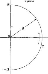
Dugundji10,9 uses the Nyquist diagram for this purpose. It is necessary to examine the number of times the curve of ДО) encircles the origin as s traces an infinite semicircle on the right half-plane (Fig. 10.16) in the counterclockwise direction. Along the imaginary axis, j = ik, ДО)

* The functions An(j)/A(j), An(s)/A(s), etc., are proportional to the transfer functions. From the general interpretation of the transfer functions it is clear that, if s is replaced by ik, then An(ik)IA(ik), etc., represent the admittance of the dynamical system to

reduces into A(ik), which is exactly the flutter determinant A as given in Eq. 18, § 6.9. Along the semicircle, j = Rel6, ^ ~ ^ ^ б < ^ j

lim C(- is) -> $ (8)

R—»-co

which can be easily seen from Eqs. 8a, 8b of § 6.9 or deduced from the asymptotic expansion of the Hankel functions in Eq. 8, § 6.9. Therefore A(s’) tends to a constant on the semicircle as R -> со:

Подпись: (9)— (/M + 1) — a

lim A(j) -*■

и-"* — fixa + a — [irf — a[29] [30] [31] [32] —-

At the origin, s = 0, Eqs. 3, 7 show that A(^) has a pole of order four. The contour of mapping must be deformed by describing a small semi­circle from ei to — si on the right half-plane. The corresponding change in the phase angle of A(s) is 477.

The mapping of A(s) can now be made without difficulty. When j = ik, the real and imaginary part of A {ik) can be computed from Eq. 19, § 6.9. Note that A (ik) need be calculated for positive values of к only. Let C(k) denote the complex conjugate of C(k), then we have

C(- k) = C(k) (10)

i. e.

as t -*■ со.

FLUTTER

C(k) = F + iG, C(- k) — F — iG

This is obvious from the definition of C{k) given in Eq. 6 of § 6.9, by re­placing к by — k, і by — i. It can also be seen from Eqs. 8, § 6.9. So

Д(- ik) = A(ik)

The mapping of the negative imaginary axis is just the mirror image in the real axis of that of the positive imaginary axis.

Example. Consider a wing with the following physical parameters:

Ц — 10, ak == — 0.2, xx — 0.1, л*2 = |-

coJcoa = b = 6/27T = 0.9549 ft, t»a = 12 cycles per second

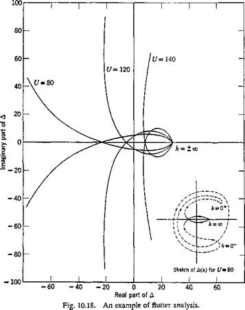
The map of the semicircle on the A(j) plane is sketched in Fig. 10.18. It is clearly seen that, for the cases U = 80 and 120 ft per sec, the curve

FLUTTER

encircles the origin once in the positive direction and once in the negative direction. The net encirclement is zero. Hence, the motion is stable. In case U = 140 ft per sec, the curve encircles the origin twice in the positive direction. Hence, A(.s) has two zeros with positive real part. The wing is unstable at U — 140. An examination based on the method of § 6.9 shows that the critical flutter speed is 129 ft per sec.

The difference between the present analysis and that in § 6.9 is that, whereas in § 6.9 the equation Д = 0 is to be solved for a pair of roots kCI and UCI, in the present analysis the values of the flutter determinant Д are examined as к varies from — oo to со.

The present method has a definite advantage when the flutter speed is so high that the effect of compressibility becomes important. As the contours are calculated for each specified speed U, the Mach number is known and the appropriate aerodynamic coefficients can be obtained directly from existing tables. Hence, the result of each calculation is a positive statement about the stability of the system, and the iterative correction for the Mach number effect is unnecessary.

TRANSFER FUNCTIONS

It is convenient to introduce a terminology for the statement of physical problems in the s language. Suppose that an input Yt{t) to a mechanical or electronic system is connected with the output Y0(t) by a linear differential operator:*

№ Y0(t) = 7,(0 (1)

In general, the transformed equation can be written as

y0(s) = F(s) Vi(s) + A(s) (2)

where

y0(s) = js?{ вдк), у is) = ад*}

* An integral operator of the convolution type leads to the same result.

F(s) is a function of s depending solely on the operator /(£>), and A(s) is a linear function of the initial values of Y0(t) and its derivatives.

If F(s) tends to a finite value when s -> + 0, the limit

lim F(s) — К (3)

s—>+0

is defined as the gain, and the function

GW = ^(S) (4)

is called the transfer function of the given operator.

TRANSFER FUNCTIONS TRANSFER FUNCTIONS

To clarify the physical meaning of the gain and the transfer function, let us consider the following simple example:

TRANSFER FUNCTIONS Подпись: (7)

It follows that

Y0(t) = (1 – e-«*) 1(0

Подпись: then TRANSFER FUNCTIONS Подпись: 1 T s Ts -j- 1 Подпись: (8)

In the special case Yt(t) — l(r), so that yfs) = l/s,

TRANSFER FUNCTIONS Подпись: K= 1 Подпись: (9)

The input and output are shown in Fig. 10.9. It is seen that the output lags behind the input, and that, at a time t — T, the output has reached 63 per cent of its asymptotic value for t -> со. The limiting ratio

shows that the gain К represents the limiting value of the response to a unit step function as t -» со.[27]

TRANSFER FUNCTIONS

In the special case F,(0 = A ewt where A is a constant,

Hence,

вд-ГГЙ5′<~’"”Че“) (10)

The first term tends to zero as t increases; it represents the transient

l

Подпись: InputПодпись: tYt(t)

Подпись: Fig. 10.9. The input and output for the differential system 5.

0

disturbance associated with the initial application of Yt(t). The second term represents a steady-state solution. The ratio

[ ^o(Q]steady ____ ^ П11

Yt(t) ~ 1 + icoT ( ’

is the same as F(iw) obtained from F(s) by replacing s with ico. Thus, for a sinusoidal input,

[ Fo(0]steady “ F(io)) YJt) (12)

It is clear then that F(m) represents the frequency response of the dynamic system, and that the gain К represents the limiting value of the response when со -» 0. The transfer function G{ia>) is the ratio of the frequency response to the response at zero frequency.

It is convenient to write the complex vector G(ico) in terms of its magnitude M and its phase angle в,

G(ico) = Me* (13)

For the present example, Eq. 7 gives

M = ;■ tan в — — CoT (14)

Vl + со2Г2

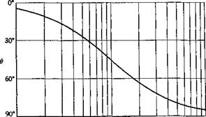
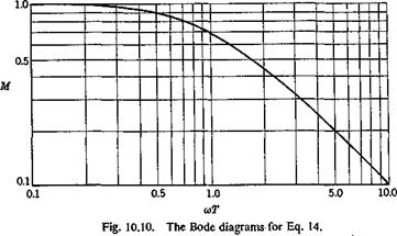
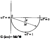
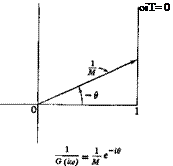
It is customary in electrical engineering to plot M and в as functions of со on a logarithmic paper (the Bode diagrams), and also to plot the locus

TRANSFER FUNCTIONS

0.1 0.5 1.0 5.0 10.0

uT

TRANSFER FUNCTIONS

Подпись: G (ico) = Me1® TRANSFER FUNCTIONS

of G(im) as a vector on a complex plane, or the locus of jG{m) — (1 jM)e~id (the Nyquist diagrams). For the example defined by Eqs. 5, the Bode and Nyquist diagrams are shown in Figs. 10.10 and 10.11.

Fig. 10.11. The Nyquist diagrams for Eq. 14.

Evidently F(ico) is exactly the mechanical admittance defined in § 8.1. Let us consider the combination of several mechanical systems into a circuit. For a series arrangement of n elements as shown in Fig. 10.12, let the rth element have a gain Kr and a transfer function Gr(ia>) — МгегЄ’.

Подпись:, У п~Уо

Fig. 10.12. Combined elements.

This series array is equivalent to a single block having a transfer function G(im) and gain K:

К = KXK2 ■ ■ ■ Kn

G(im) –= ■ ■ • (Mnei6-) (15)

= (AfjAfa • • • Мп)еі(в’+в*+”’ +e")

The over-all transfer function G(ia>) = Меів can thus be determined:

Подпись:logjo M = log10 Mt + log10 M2 + • ■ • + log10 Mn

0 — 0i + 02 + ‘ ‘ ‘ + 0«

As another example a simple feedback servo is shown in Fig. 10.13. The input у{ passes through a block with gain Kx and transfer function Gx{s)

(Д ~ У*‘(Д ~ агУ’ •••(■?- атУп

(Д – b^Hs – b2)x‘ •••(*- bnf-

and produces the output y0 which is fed back through an “adder” to the input, so that the resultant input becomes yi — y0. In this case


У о = КіСхІУі – y0)


we have


(17)


A somewhat more general case is shown in Fig. 10.14, for which


(18)


(1)


TRANSFER FUNCTIONS

(1)


where A is a constant, аъ a2, • • •, am are the zeros, and Ьъ b2, • • •, bn


are the poles; the positive integers уъ, м2, • • * j A2> • are the

orders of the zeros and poles, respectively. We assume < SA,-.

The location of the poles is important in determining the stability of the solution T0(!) which can be derived according to Heaviside’s expansion theorem. Expanding G(s)/s into partial fractions, we have terms of the form

TRANSFER FUNCTIONS(2)

associated with each pole Ьг. Therefore, when the input Y{(t) is a unit-step function, yt(s) = 1 js, the inverse transform involves the term

Obviously the solution (3) is “stable” (remains finite as t -> oo) if the real part of b{ is negative, and is “unstable” (becomes unbounded) if the real part of b{ is positive. Thus a necessary condition for stability is that the transfer function should have no poles in the right half-plane R1 л – > 0. This conclusion holds also for transcendental transfer functions: If y0(s) has no singularity on the right half-plane R1 s > 0, then the inverse Y0(t) remains finite as t -» oo. If y0(s) has a pole on the right half-plane, then Y0(t) becomes infinitely large as t -> oo. (See footnote on p. 360.)

Hence, if the transfer function G(s) is a rational function, the problem of stability is to find whether the real parts of all the roots of the denominator are negative.

The conditions for a polynomial with real coefficients

Подпись: (4)P(s) = p0sn + p1sn-1 + • • • 4- pn-lS + Pn

to have only pseudo-negative roots (i. e., the real parts of all the roots are negative) are the well-known Routh-Hurwitz conditions. They are given in Appendix 2. This algebraic problem has been generalized to include polynomials with complex coefficients by Sherman, DiPaola, and Frissell.11,20,11-21 An application of these results solves the stability problem completely when G(s) is a rational function.

A different method is introduced by Bode and Nyquist (see Ref. 10.10) and is based on Cauchy’s theorem in the theory of functions of a complex variable. It is applicable to transcendental transfer functions.

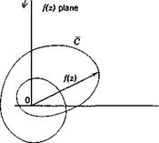
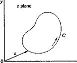
Let S be a region on the (x, y) plane bounded by a simple closed curve C. A complex-valued function f(x, у) = ф(х, у) + іxp(x, у) defined in S may be regarded as a function of a complex variable z — x + iy and written as f(z). When 2 traces the curve C, the locus of the complex

TRANSFER FUNCTIONS
TRANSFER FUNCTIONS

number f(z), when plotted on a complex plane, gives a curve C (Fig. 10.15). Now there is a theorem in the theory of functions of a complex variable which states that iff(z) is analytic in S and continuous on C, and does not vanish on C, then the excess of the number of zeros over the number of poles of f{z) within C is (1/277) times the increase in argjz) as z goes once around C in the positive direction.[28] This result is sometimes called the principle of the argument, and is easily derived from the theorem of residue, considering the residue of the function f'(z)/f(z) in C. A zero of order r is counted as r simple zeros, and a pole of order s is counted as j simple poles. The positive direction of C is so defined that, if an observer

Fig. 10.15. Locus of/(z) as z traces a closed curve C.

moves along the curve C in the positive direction, the region S enclosed by C appears to his left-hand side.

This principle can be applied as follows. If we wish to find the number of zeros of f{z) in a contour C, we determine (a) the change in the argu­ment of f(z) as г goes around C in the positive direction, and (b) the number of poles off(z) in C. Then

о. ^ change of argument of f(z) . , . „

No. of zeros in C — —:———————————— + no. of poles in C

277

The number of poles can usually be determined by inspection. In particular, iff(z) is a polynomial, it has no pole in any contour C.

As a particular application, if the number of zeros of jz) in the right half-plane, R1 z > 0, is to be found, we may consider a contour C con­
sisting of a large semicircle of radius R in the right half-plane (Fig. 10.16). In the limits when R tends to infinity, the entire right half-plane will be enclosed in C. Observe the locus off(z) as г goes round C once. If it encircles the origin of the f{z) plane n times in the counterclockwise direction, f{z) changes its argument by Ъпт. If the number of poles in the right half-plane is known to be p, then the number of zeros in the right half-plane is n + p.

TRANSFER FUNCTIONS TRANSFER FUNCTIONS

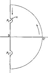
The contour C must not pass through any pole or zero of /(г). If there are zeros and poles on the desired contour C, the difficulty can be

Fig. 10.16. A semicircular Fig. 10.17. A deformed semicircular contour. contour.

avoided by making a deformation of the contour in the neighborhood of these points. Thus, as shown in Fig. 10.17, if pt, p2 are poles on the imaginary axis and C is chosen as semicircle, we may take a deformed contour C which circumvents the poles by small semicircular arcs of radius e and let e 0. If px is a pole of order n, we may write, in the neighborhood of px,

where g(z) is finite in the neighborhood of px. Let z — px = sea, ‘then
№ = £ Ырд + 0(e)] Є~іп0

Thus, when z goes around the small arc from в = тт/2 to в = — w/2, the change in phase off(z) is rm.

When the contour C is symmetrical with respect to the real axis, it is useful to remember that, when f{z) is a polynomial or a rational function with real coefficients, or is a combination of elementary functions with real coefficients,

/©=/(г)

where z and / denote the complex conjugate of z and /; i. e., z — x + iy, z = x — iy, etc. Thus, if f(z) corresponding to the upper half of the contour C is known, that corresponding to the lower half can be obtained by a mirror reflection in the real axis.

RESPONSE TO GUSTS—RIGID AIRPLANE, PITCHING NEGLECTED

Let us assume, as in § 8.2, (1) that the airplane is initially in horizontal flight at a constant speed U, (2) that the gust is normal to the flight path of the airplane and has a velocity distribution w in the direction of flight and is uniform spanwise, (3) that the variation of the forward speed of the airplane as it traverses the gust can be neglected, and (4) that the gust intensity and the induced motion are so small that the linearized aero­dynamic theory is valid. Whereas in § 8.2 the quasi-steady aerodynamic coefficients are used, we shall now show how the unsteady aerodynamic forces can be taken into account.

The equation of motion of the airplane having one degree of freedom is

mz = — L (1)

where m is the total mass, z the downward displacement, and L the upward lift.

The lift consists of two parts; that arising from the motion of the airplane, and that induced by the gust.

The lift induced by the motion of a two-dimensional airfoil in an incom­pressible fluid has been derived in § 6.7. As in § 6.7, it is convenient to introduce the dimensionless time parameter r: 2

Подпись: L(r)=~plPSa Подпись: - г'(0)Ф(т) c Подпись: — Г Ф(т — a) z"(a) da A,— z"(r) c Jo c Подпись: (3)

where c denotes the chord length. A dot will indicate a differentiation with respect to the physical time t, whereas a prime will indicate a differ­entiation with respect to r. Thus z — dzjdt, z’ — dzjdr, z = (2 Vjc)z’. According to Eqs. 8 and 9 of § 6.7, we may write the lift induced by an airplane motion which starts at r = 0 as

In the above equation, p is the density of the fluid, S is the wing area, a = dCLjdct. is the steady-state lift curve slope (per radian), and Ф(т) is Wagner’s function. Whereas the equations in § 6.7 are written for a two – dimensional flow of an incompressible fluid, Eq. 3 may be considered applicable to compressible fluids when Ф(т) is properly modified for Mach number. Strip assumption is assumed for the aerodynamic action, and the finite span effect will be corrected in an overall manner by correcting the lift curve slope a for aspect ratio as in a steady flow.

The lift induced by the gust can be expressed by a similar equation, based on a fundamental function T(t), which represents the ratio of the transient lift to the steady-state lift on an airfoil penetrating a sharp-edged gust normal to the flight path. Let the speed of the sharp-edged gust be w; then by definition the transient lift coefficient is

CjJr) = a ~T(t) (4)

where a is the steady-state lift-curve slope, and т is the dimensionless time parameter as before. It is convenient to interpret т here as the distance traveled by the airfoil, measured in semichords.

Tables 10.2 and 10.3 give the approximate expressions of Ф(т) and T"(r) at Mach number zero, obtained by R. T. Jones15-43 for elliptic wings. For T(t) it is assumed that the leading edge of the airfoil en­counters the sharp-edged gust at the instant r — 0.

Table 10.2. Wagner’s Function Ф(т) at M = 0

Ж

Ф (t)

a

3

1 – 0.283e-°-S4OT

1.27Г

6

1 – 0.361e-°-38lT

1.577

CO

1 – 0.165e-°-04Sr

– 0.335°—°-300t

277

Table 10.3. Kiissner’s Function ‘F(t) at M — 0

Ж

‘F(t)

а

3

1 – 0.679е~°-558т – 0.227е-3-20т

1.2тг

6

1 – 0.448е~°-290т – 0.272е-°-725т – 0.193<?-3-00т

1.5тг

CO

1 – 0.500е-°-130г – 0.500е~г

27т

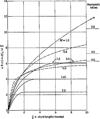
Figure 10.4 shows the results of a linearized theory for the indicial admittance of a two-dimensional airfoil entering a sharp-edged gust. In

RESPONSE TO GUSTS—RIGID AIRPLANE, PITCHING NEGLECTED

Fig. 10.4. Indicial admittance of the lift of a restrained wing to unit sharp – edged gust. Two-dimensional wing for several Mach numbers. From Lomax, Ref. 15.84. (Figure reproduced by courtesy of the NACA.)

order to indicate the effect of compressibility, the ratio dCL/d = аТ(т)

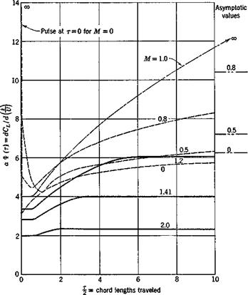
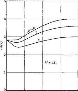
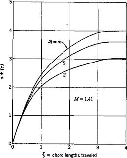
is presented. Figure 10.5 shows the indicial admittance of a two-dimen­sional airfoil to a sudden sinking speed, i. e., ЭСХ/Э = а Ф(т). The

effect of finite-aspect ratio at Mach number 1.41 is shown in Fig. 10.6. These results are given by Lomax.15,84

RESPONSE TO GUSTS—RIGID AIRPLANE, PITCHING NEGLECTED

Fig. 10.5. Indicial admittance of the lift to a sudden sinking speed as a function of chord length traveled. Two-dimensional wing for several Mach numbers. (Figure reproduced by courtesy of the NACA.)

The lift induced by a variable gust can be written as a Duhamel integral. Since Y(0) = 0, we obtain, according to Eq. 27 of § 8,1,

. Ur) = plPSa Ґ ^ – a) da

2 Jo U

RESPONSE TO GUSTS—RIGID AIRPLANE, PITCHING NEGLECTED

0 12 3 4

j = chord lengths traveled


RESPONSE TO GUSTS—RIGID AIRPLANE, PITCHING NEGLECTED

Fig. 10.6. The effect of finite-aspect ratio on аФ(т) and aV(r) at Mach number 1.41. Rectangular wings of aspect ratios 2, 5, and со. (Courtesy of

the NACA.)


Again the strip assumption is used here and a is corrected for aspect ratio. The prime over Y’ indicates differentiation with respect to the variable r. The equation of motion of the airplane is therefore

(s + 0.130X5 + l)(s3 + axs2 + + a3) (1 )

where

0.345,m + 0.3363 0.0135,m + 0.1436

^ + 0.25 * "2 ~ 7+^25

0.006825 ’

3 ju + 0.25

z"(t) can be found from Eqs. 13 according to Heaviside’s expansion as demonstrated in § 10.2. From z"(t) the acceleration z in physical units is obtained:

5 = U2 Z"(T) (15)

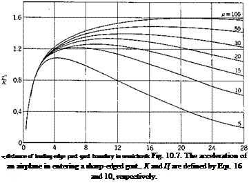
Подпись: T, distance of leading edge past gust boundary in semichords Fig. 10.7. The acceleration of an airplane in entering a sharp-edged gust.. К and Ц are defined by Eqs. 16 and 10, respectively.

The maximum acceleration calculated from Eq. 15 is smaller than that given by Eq. 9 of § 8.2, where quasi-steady aerodynamic coefficients are

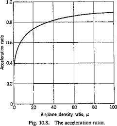
used. The ratio between the values of the maximum acceleration given by Eq. 15 and Eq. 9 of § 8.2 represents the effect of the lag in time for the circulation to grow after encountering the gust. This ratio can be obtained by dividing smax by the quasi-steady value — (U//tc)w0.

The calculated result of z" in an incompressible fluid, expressed in units of K, where

Подпись:(16)

is shown in Fig. 10.7. The true value of z" is the value shown in the

figure times the value of K. The acceleration ratio 2rnax/(maximum quasi­steady acceleration) is shown in Fig. 10.8. The importance of the airplane density ratio ц on the gust-response characteristics of an airplane is evident.

For other gust profiles, we may either use Eq. 9 directly with proper to find the inverse transform, or use the response to a sharp-edged

RESPONSE TO GUSTS—RIGID AIRPLANE, PITCHING NEGLECTED

gust obtained above to generalize by a Duhamel integral. The latter is a more practical procedure.

ORDINARY LINEAR DIFFERENTIAL EQUATIONS WITH CONSTANT COEFFICIENTS To solve the equation

with the initial values x0, xlt • • •, xn_1 for x, dxjdt, • • •, dn~1xjdtn’1 when t = 0, where аъ a2, ■ • ■ are constants., we transform every term of the equation into its Laplace transform. Remembering the differentiation rule, we obtain the transformed equation:

examples appear in the classical theory of airplane dynamics. When the deformation of the main structure is described by a few generalized coordinates, ordinary linear differential equations are obtained. The principal assumptions responsible for such great simplification are (1) that the motion of the airplane consists of infinitesimal disturbances about a steady symmetrical flight, and (2) that the dependance of the aero­dynamic forces on the rate of change of linear and angular velocities can be neglected except for the lag of the downwash between the tail and the wing. With the second assumption the unsteady aerodynamic action is expressed as a linear function of the linear and angular velocities, the coefficients being defined ‘as “stability derivatives.”

The extensive and intricate subject of airplane dynamics, however, will not be discussed here. (See Refs. 10.10-10.13.) In the following sections, illustrations of the application of Laplace transformation will be given in the gust-response and flutter problems.

APPLICATIONS OF LAPLACE TRANSFORMATION

The method of Laplace transformation can be applied to a number of aeroelastic problems. In this chapter the mathematical background will be outlined briefly, and’ its applications will be illustrated by examples in gust response and flutter.

10.1 LAPLACE TRANSFORMATION

The method of Laplace transformation is extremely powerful in treating certain response problems. Its mathematical foundation and refinements cannot be treated in this book because of the limited space. However, there exist many good books on this subject.101”10-7 Hence, in the following, we shall only quote the rules of the method of Laplace trans­formation, and give some heuristic derivations to help understand them.

The Laplace transform of a function F(t), which vanishes for t < 0, is defined by the integral

Подпись: (R1 s> a)Подпись:&{F{t)s} =^e~slF{i) dt

The inverse transform is given by the equation

F(t) = ——. f es,£F{Fs) ds (c > a)

2m Jc—i oo

where a is a real number greater than the real parts of all the singular points of SF{Fs). Whenever these integrals exist, F(t) and ££{Fs) are called the original and the image, respectively. If there is no confusion, the image £f{Fs} will be written as ^£{F).

The conditions for the validity of the reciprocal relations 1 and 2 depend much on the sense of integration of the integrals. If the integrals are taken as Cauchy principal values in the Riemannian sense, a set of sufficient conditions which guarantees the validity of the Laplace trans­formation is

1. The integral 1 is absolutely convergent in the region Rl. s > a.

2. Fit) is of bounded variation in any finite interval, and F(t) = 0 for t < 0.

APPLICATIONS OF LAPLACE TRANSFORMATION
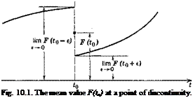
Подпись: Fig. 10.1. The mean value F(ta) at a point of discontinuity.

If these conditions are satisfied, the reciprocal relations between F(t) and £F{Fs) are essentially unique.

Example 1. Let F(t) = l(t); i. e., Fit) — 1 when t > 0, Fit) — 1/2 when t = 0, and F(t) = 0 when t < 0. Then

&{Чф} = e~sldt=-~e-st Jo S 0

Hence, when R1 s > 0,

Example 2. Let F(t) = ekt when t > 0. Then

f OO,

FF{ekt} = e~st eu dt =—————- (R15 > R1 k)

Jo s — к

Following van der Pol and Bremmer,10-7 we shall regard the method of Laplace transformation as a language. In actual applications we first transpose the problem under consideration, which is formulated in terms of the variable t, into a new problem in the variable s; i. e., the functional relations (such as differential and integral equations) in which the problem is first stated are transformed into their operational equivalent. This is done by multiplying the given relation or relations by the function e~st and then integrating from t = 0 to t = oo. This is a transition from the t language to the s language. In many problems the new problem in the ■s language is considerably simpler than the original one in t, and therefore leads to an easier solution. Once the problem is solved in terms of s, it only remains, as the second stage of the method, to translate the і solution back into the physical language of t.

For the purpose of such translation between the s and t languages, a “dictionary” is necessary. An abridged one is given in Table 10.1. A complete dictionary is given by Erdelyi.108

The user of the language must know the “grammatical” rules by which the 5 and t languages are translated into each other. A few basic rules are quoted below. They are constructed on the basis of Eqs. 1 and 2. But, in applying the dictionary and grammar, these integrals need no longer be used explicitly.

Linearity. The Laplace transformation is linear; i. e., if A and В are constants, then

££{A F(t) + В G(t)} = A ££F) + BF£{G)

Подпись: Example 3. Подпись: 1 1 2 s -f к
APPLICATIONS OF LAPLACE TRANSFORMATION APPLICATIONS OF LAPLACE TRANSFORMATION

This follows from the definition of the transformation. Hence, a multi­plication of the original by any constant A corresponds in the s language to a multiplication of the image by A, and the image of the sum of two originals is equal to the sum of the separate images.

i. e.,

.5?{sinh kt} = —

S’" K~

Similarity Rule. Let

JF{F(t)} = f(s) (a < Rlj < oo)

Then, if A is a positive real constant,

SF{F{k)} = j j (Aoc < Rb < oo)

Example 4.

-5P{cos t} = – r-y—г; SO ^{cos kt} — S

sz + 1 sz + кг

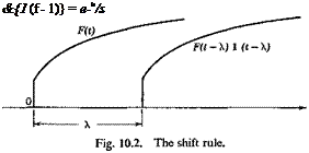
Shift Rule. If /(s’) is the Laplace transform of F(t), then e >sf(s), Я > 0, is the transform of the function F(t — Я) 1 (t — Я), where 1 (t — Я) is the unit-step function.

This is seen from the following equation:

ГF(t – Я) l(r — X)dt = Ге-Н F(t – Я) dt = e~u (“e~a F(t) dt JO J A Jo

Note that

(0 when t <X

F(t – Я) 1 (t — A) = !

1 F(t — A) when t > A

The function F(t — Я) 1 (t — A) is obtained by shifting the original function F(t) to the right through a distance X (Fig. 10.2).

Example 5. Since

^{1(0} =

Подпись: &{1 (f - 1)} = e-u/s

we have

and the Laplace transform of a square wave of band width 2a is (Fig. 10.3)

&{1 (t — A) —(t — A — 2a)} = і (e’u – е~и’ш)

= – e-<A+als sinh as s

Example 6. In automatic control of airplane lateral stability, it is sometimes advantageous to gear the rudder angle 6r to the yawing acceleration ip, but lagging by a specified time interval, т:

The factor e_TS is often called a lag operator.

Attenuation Rule. If

£Є{Р(()} = f(s) (a < R1 j < oo)

then

Подпись: [a + R1 A < R1 (s + A) < со]£’{e-uF(t)}=f(s + A)

■ПШ =Ms)

= Л(*)

Подпись: (oq < R1 s < со) (а2 < R) s < со)

This follows directly from substitution into the definition integral (Eq. 1).
Convolution Rule. If F*(/) and F2(/) are piecewise continuous and

then

fi(s)f2(s) == ^{F^tfF^t)} (max (oq, a2) < R1 s < oo) where Fx{t)*F2(t) is the so-called convolution integral:

F&YF&) = f Vx(r) F2(t – r) dr = Pfx(/ – r) F2(r) A-

Jo Jo

This is probably the most important of all rules.

A formal derivation of this rule is as follows:

J

* 00 /*00

e~m FJu) du I e~nF4p)do

0 Jo

= f00 f °V(“+,,,S Fx(u) F2(v) du dv Jo Jo

Introducing a new variable t — и – j- v, and letting the variables (и, v) be transformed into (и, /), we have

fi(s)Ms) =j^ J e~ts Fx(m) F2(/ – u) du dt

Подпись:Fx(m) F2(/ — u) du

The role of iq and F2 are obviously interchangeable. Hence, the last equation is equal to

Ms) 40) = І е~л dt f Fx{t – u) F2(u) du Jo Jo

The last two equations state the convolution rule.

Differentiation Rule. Let

JF{F(t)} = f(s) (a < R1 j < oo)

If F(/) has a derivative F'(t) for t > 0, and if the Laplace transform of F'(t) exists, then

nnt)} = Ф) – Я0 +)

where F(0 +) means the limit lim F(0 + є), є > 0.

e—>0

Hence, a differentiation of the original with respect to t corresponds to a multiplication of the image by a factor s.

A formal derivation of this rule is as follows. By a formal integration by parts, we have

ЩПО} = Гe~st F'(t) dt
Jo

Подпись: F(t) dtAPPLICATIONS OF LAPLACE TRANSFORMATION‘ Д0

provided that the limit of e~siF(t) tends to zero as t —> cc.

Let us remark that the continuity of the function Д0 is important for the validity of the above formula. If Д0 is continuous except for an “ordinary” discontinuity at t — t0, we would have

ЩРЩ = sf(s) – ДО +) – [Дг0 + 0) – Дг0 – 0)] є"’"8

where the quantity in the brackets is the jump of Д0 at t = t0.

Repeated application of the above rule leads to the following: Successive Differentiation Rule. Let the function F(t) be n times differentiable for t > 0, and let the Laplace transform of the uth derivative Fln)(t) exist for a < R1 s < oo. Then F(t) has a Laplace transform for all s, R1 s > a, and