Category An Introduction to THE THEORY OF. AEROELASTICITY

STATISTICAL ASPECTS OF DYNAMIC-STRESS PROBLEMS

In the preceding section the response of an airplane to a specific gust is discussed. In applying such an analysis to the practical design of an aircraft, we must know how to specify the gust profile.

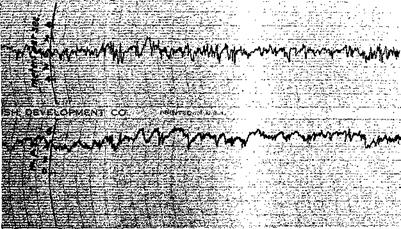
Figure 8.6 shows a record of vertical gusts measured by a hot-wire anemometer carried on a stationary balloon (fastened to the ground by wires) 146 meters above the ground.[22] It is similar in nature to the anemometer records of wind-tunnel turbulences. From such a figure it is indeed impossible to say what kind of an isolated gust profile can characterize the real picture.

Similar difficulty arises in other dynamic-stress problems. In fact, one of the most difficult problems in structural design with regard to transient loads is the determination of the forcing function, or the selection, among

STATISTICAL ASPECTS OF DYNAMIC-STRESS PROBLEMS

Fig. 8.6. A gust record. (Courtesy of Dr. P. MacCready of the California Institute of Technology.)

the great variety of possible forcing functions, of those to be used as a basis for design. The exact form of the forcing function is always uncertain to some extent because of the large number of variables entering the problem. Thus, when a few important variables are considered in a calculation, other variables appear as disturbing influences. The rartdom nature of the atmospheric turbulence as shown in the records of Fig. 8.6 are due to the influences of the viscosity, pressure, density, temperature, and humidity of the air and the initial velocity distributions, varying in such a complicated manner that a mechanistic prediction based on the hydrodynamic equations is practically impossible.

If the uncertainty of predicting the forcing function is recognized, the problem becomes statistical. One then tries to state the main features of the response, as well as those of the forcing function, in terms of

statistical averages and probability distributions. The statistical termin­ology will first be explained in the next three sections. The “gust” response of an airplane, to a continuous atmospheric turbulence such as the one recorded in Fig. 8.6, is then calculated.

RESPONSE OF AN AIRPLANE TO A GUST OF SPECIFIED PROFILE

One of the critical design conditions for airplane structures is the gust loading, which the airplane encounters when flying through a turbulent atmosphere. It is customary to assume that the nonuniformity in the flow consists of small disturbances superimposed on a uniform steady flow. Generally, only the component of the disturbing velocity normal to the flight path is considered. Such normal disturbances are called gusts.

To study the response of an airplane to a gust, let us make the following assumptions

1. The airplane is rigid.

2. The disturbed motion is symmetrical with respect to the airplane’s longitudinal plane of symmetry, but the pitching motion can be neglected.

3. The airplane is initially in horizontal flight at constant velocity U.

4. The gust is normal to the flight path, and is uniform in the spanwise direction.

5. The variation of the forward speed of the airplane can be neglected.

6. The quasi-steady lift coefficient may be used, and the chordwise distribution of the gust velocity may be regarded as constant at any instant and equal to the gust at the mid-chord point.

The disturbed motion of the airplane, consequently, has only the degree of freedom the vertical displacement z (measured at the airplane’s center

of mass, positive downward). According to Newton’s law, the equation of motion is

mz — — L (1)

where m is the total mass of the airplane, L is the total lift (positive upward), and a dot indicates a differentiation with respect to time. To derive an expression for the lift L, the gust profile must be specified. Evidently, it is the gust distribution relative to the airplane that is of significance. Hence, no generality is lost by regarding the gust speed, w(t), as a function of time. Then, according to assumption 6, the lift can be written as

RESPONSE OF AN AIRPLANE TO A GUST OF SPECIFIED PROFILE

where p is the density of the air, and 8 is the wing area. Using Eq. 2 and introducing a parameter A, of physical dimension [Г-1],

(3,

2m ax

we can write Eq. 1 as

z = — A(w + z) (4)

This equation is to be solved for the initial conditions

z = z = 0 when t — 0 (5)

An integrating factor of Eq. 4 is easily seen to be eu. Equation 4 may be written as

j

— (zeu) = — hv{t) eu at

Integrating, and using Eqs. 5, we obtain

z(t) = — Ае_Д( J w{x) dx

A second integration gives

z(t) — — А Г е“Дт dr f w(x) elx dx Jo Jo

Changing the order of integration, we have

z(t) = — A f w(x) elx dx f e~x~ dr Jo Jx

i-e.,

If w(x) is a step function, the so-called sharp-edged gust, so that ii’(a;) is equal to a constant w0 for x > 0 and vanishes for x < 0 (Fig. 8.5), then an integration of Eq. 6 leads to

<t) = j w0(l – e~u) – иу (7)

and

z(t) = — Xw0 e~u (8)

The acceleration reaches the maximum when / = 0.

Подпись: (9)2wn

Dividing zmax by the gravitational acceleration g, we obtain the sharp – edged gust formula

_ Anax _ ^ ^0__ pU Sw, dCL

g g 2 mg d*

(10)

where An denotes the increment of load factor. The product of An and the weight of the structures gives the acting inertia force.

Equation 7 is the indicial admittance of the displacement z for a sharp – edged gust. Equation 6 is the Duhamel integral for an arbitrary gust

RESPONSE OF AN AIRPLANE TO A GUST OF SPECIFIED PROFILE

w0

Sharp-edged gust

Fig. 8.5. Sharp-edged gust.

profile. According to § 8.1, the same problem can be as easily solved by the method of mechanical impedance, in which the response to a sinu­soidal gust, w0 sin mt, is first obtained. The response to an arbitrary gust can then be obtained by a Fourier integral. It is easy to show that the results obtained by these two methods agree with each other.

The sharp-edged gust formula is derived under the six simplifying assumptions named above and the idealized gust profile of Fig. 8.5. In reality, none of these assumptions can be fulfilled. Nevertheless, the formula is convenient for use in airplane design. If the gust speed is based on an “effective” value which is derived by reducing the experi­mental acceleration data according to Eq. 10, the result can be used to predict the gust load factor on similar airplanes. The effective gust speed Wo, however, would have to be determined for each type of airplane, because the effects of the simplifying assumptions are different for different airplane size, geometry, flexibility, center-of-gravity location, dynamic stability characteristics, and flight Mach number.

Much work has been done in the direction of relaxing one or another of the assumptions made in deriving the sharp-edged gust formula. Using aerodynamics of an unsteady incompressible flow, KUssner8,20 obtained in 1931 the response of a rigid airplane, restrained against pitch, to a gust with a finite velocity gradient. KUssner also extended his analysis to take into account the elasticity of the wing in bending, but assumed the deflection mode to be of the same form as the static deflection curve under a uniformly distributed load. He concluded that the stresses in an elastic wing may be considerably higher than that in a rigid wing. In addition, he showed that, for a gust of given intensity, the load factor reaches a maximum when the gust is inclined at 65° to 70° to the flight path, but the load factor due to a normal gust (gust velocity perpendicular to the flight path) differs from this maximum by less than 10 per cent. The response of a rigid airplane free to pitch is treated by Bryant and Jones in 19328,5 under the assumptions of quasi-steady lift, and in 19368,6 for a semirigid wing including the unsteady-flow characteristics as given by Wagner. Similar extensions were made by Williams and Hanson8-36 in 1937, Sears and Sparks8,32 in 1941, and Pierce8-24 and Putnam8,27 in

1947.

More extensive investigation on the effect of elastic deformation was made by Goland, Luke, and Kahn8,10 in 1947. Jenkins and Pancu8,16 in

1948, Bisplinghoff, Isakson, Pian, Flomenhoft, and O’Brien8,3’8,4 in 1949. In these studies the bending and torsion deflections of the wing are approximated by a number of deflection modes.

A comprehensive analysis of the effect of the gust gradient and the airplane pitching was made by Greidanus and van de Vooren8,11 (1948). The allowance of the pitching degree of freedom introduces great compli­cation into the analysis because of the phase lag in the downwash between the wing and the tail.

Further extensions were made by Bisplinghoff and his associates, Mazelsky, Diederich, Houbolt, and others, to account for aerodynamic forces in a flow of a compressible fluid.

Since transient problems can be best treated by the method of Laplace transformation, details of some of these extensions will be discussed in Chapter 10. In the remaining sections of the present chapter, let us turn to the statistical aspects of the dynamic-stress problem.

SOME MATHEMATICAL CONCEPTS

The Concept of Complex Impedance and Admittance. In § 1.8, it is shown that the steady-state solution of the equation

272

SEC. 8.1

SOME MATHEMATICAL CONCEPTS

273

d2x

m~di2

dx

+ p – + Kz = (p> 0)

(1)

may be written

as

F Jut

(2)

where

Z(/a>) = m(ico)2 + f>(ioj) + К

(3)

Equations 1 and 2 may be compared to the relations between the electromotive force E{t) and the current I{t) flowing in an electric circuit:

L~ + Rl+r; (Idt = E dt C Jo (4)

/(0 = E(t)IZ

where Z is the impedance of the circuit which depends on the frequency со of the electromotive force, the inductance L, resistance R, and the capitance C of the circuit:

Z = icoL + R + (5)

icoC

By the anology between Eqs. 2 and 4, Z(iaj) is called the impedance of the system represented by Eqs. 1. – If Eq. 1 represents a mechanical system, Z(ico) may be called the mechanical impedance. Its inverse, l/Z(ico), is called the admittance.

The response of a linear system to an exciting force that varies har­monically is simply given by multiplying the exciting force by the admit­tance.

In engineering literature a different notation is often used by putting s = /со and writing Z(s) instead of Z(ico). Note that Z(s) can be obtained directly from the differential equation by a formal process of replacing

the operator d/dt by the symbol s, and J dt by 1 js.

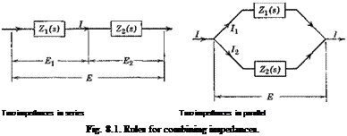
The rules for calculating the impedance of a circuit are the same as those for combining the electrical resistance. Thus (Fig. 8.1), if Z1 and Z2 are in series, the resultant impedance is

Z = Zi + Z2 (6)

On the other hand, if Zx and Z2 are in parallel, the resultant Z is given by the equation

1 = 1 + 1 z Zj z2

The Principle of Superposition. Since the differential equation 1 is linear, the principle of superposition holds. In particular, if the right – hand side of Eq. 1 is

Fft) + Fft) = F10eM + F20ei2ra( a particular solution will be

Подпись: Two impedances in series Two impedances in parallel Fig. 8.1. Rules for combining impedances.

■’T і 2_ Z(ia>) Z(i2a>)

More generally, if the right-hand side is given by a Fourier series

(8)

then

As a further generalization, if F(t) is represented by a Fourier integral

m =

where

V2t7 . 1

| А{ы)еш dm

)— CO

Г c°

(10)

А(ш) =

V2tt.

F{t)e-Wt dt

) — 00

then a particular solution is

x(t) =

1

s/2n *

(11)

These processes can be justified if the right-hand sides of Eqs. 9 and 11 converge (see Chapters IX and X of Karman and Biot154).

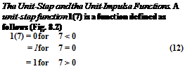
Подпись: The Unit-Step and the Unit-Impulse Functions. A unit-step function 1(7) is a function defined as follows (Fig. 8.2) 1(7) = 0 for 7 < 0 = І for 7 = 0 (12) = 1 for 7 > 0

m

1

Подпись: t = 0 Fig. 8.2. t——— *-

Unit step function.

If the point of jump is moved to the point t = t, the unit-step function is written as 1(7 — r) for which

1(7 — r) = 0 for 7 < r

= | for 7 = t (13)

= 1 for 7 > r

SOME MATHEMATICAL CONCEPTS

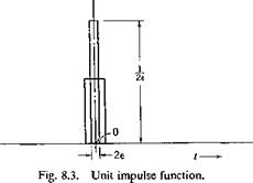
A unit-impulse function (5(7) is a function that is zero for 7 < — e and t > є, є being any positive number, but tends to oo when 7 = 0, and

the integral of (5(7) taken over the interval — £ to є is equal to 1 (Fig. 8.3). Thus, if (5(7) denotes the unit-impulse function, then (5(7) = 0 for 7 Ф 0

lim Г (5(7) dt = 1 (14)

£—>■0 J — Є

Whereas the unit-step function is well defined, the unit-impulse function, mathematically speaking, is not. But, since its introduction by Dirac,
the unit-impulse function (often called the Dirac (5-function) has become a powerful tool for physicists.[21]

Let us quote without proof (for a proof, see, for example, K&rm&n and Biot,154 pp. 394-396) the following integral representations of the unit-step and unit-impulse functions

(15)

(16)

Indicia! Admittance. The response of a physical system to a unit-step function is called the indicial admittance. In some cases the indicial admittance can be found by elementary methods. In general, the method of Laplace transformation (Chapter 10) gives the solution readily.

Подпись: Example 1.

SOME MATHEMATICAL CONCEPTS Подпись: (17)

Consider the equations

The general solution of the differential equation is

x = —- + Cx sin co0t + C2 cos co0t Щ

Using the initial conditions, we find Cx = 0, C2 = — l/co02. Hence, the indicial admittance is

A(t) = x = – i; (1 — cos «„01(0 (18)

COq

SOME MATHEMATICAL CONCEPTS SOME MATHEMATICAL CONCEPTS Подпись: (e > 0) Подпись: (19)

Example 2. Consider the same problem with the right-hand side replaced by a unit-impulse function.

Integrating the differential equation from — e to є, where є is a small number, we obtain

f£ d2x Ce

L^dt+^Lxdt = 1 (20)

The first integral in the above equation can be written as fe d ldx fe,(dx dx e (dx

J-. dt W dt Ы “ Jt Ы1-. (21)

since (dx/dt=_e — 0. The second integral in Eq. 20 tends to zero when є tends to zero, because, in the neighborhood of f = 0, |ж| is a finite number, say < K, and the integral is bounded by 2Ke, which vanishes in the limit є -> 0. Hence, in the limit, Eq. 20 becomes

The given system (Eqs. 19) is then equivalent to the following d*x

Подпись: 1

Подпись: + ш02х — 0, Ul~ л ^ і -_i„ Подпись: t > 0 t = (0 +) Подпись: (22)

dt/t=e

the solution of which is

Подпись: (23)h(t) = — sin co0t 1(f) co0

Note that the results of Exs. 1 and 2 are related by the equation

Подпись:dA

dt

A more general result, valid also when A(0) Ф 0, is (see Karman and Biot,1-54 p. 402)

Подпись: (24)Подпись: h{t) = zf(0) (3(f) +dA

dt

where A(t) is the indicial admittance and h(t) the response to a unit – impulse function.

Duhamel’s Integral. When the governing equation is linear, the principle of superposition holds. Thus, the response to the sum of two

step functions is the sum of the indicial admittances. In other words, the response to a function

C 1(0 Ч – c2 io t)

is

cx A(t) + c2 A(t — r)

where A(t) is the indicial admittance to 1(0- Now any function f(t), having a continuous derivative, can be repre­sented in the integral form

Л’)-/т+[£(г)4г

= /(0) 1(0 +£ f(0 10 – r) dr (25)

Since an integration is the limit of a summation, and since for each

jf

element “ (т) 1(г — r) dr the response is dt

Jt (0 A{t — t) dr

we obtain by the principle of superposition that the response to the function f(t) is

x(t) =/(0) A(t) + [ I(r) A(t – r) dr (26)

Integrating by parts, we obtain an equivalent form:

rt dA

x(t) =/(0 Д0) +Jo/(r) — 0-t) dr (27)

The integrals in Eqs. 25, 26, and 27 are known as Duhamel integrals.

By Eq. 24, the Duhamel integral 27 can be written as

SOME MATHEMATICAL CONCEPTSДт) hit — r) dr (28)

where h(r) is the response to a unit-impulse function.

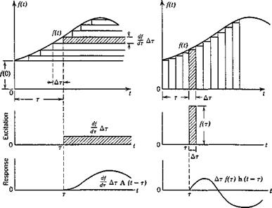
A graphical interpretation of these results is originated by von Kdrmdn and Biot1-64 and is given in Fig. 8.4 which seems to be self-explanatory.

Relation between the Admittance and the Indicial Admittance. Perhaps the harmonic function is the simplest periodic function, and the unit-step function is the simplest nonperiodic function. Nevertheless, any arbitrary function, under very mild mathematical restrictions on continuity and differentiability, can be resolved, either into simple-harmonic components

in the form of a Fourier integral, or into unit-step functions by means of a Duhamel integral. Knowing either the impedance or the indicial admittance, we can derive the response to an arbitrary forcing function by a single integration. Hence, the problem of dynamic responses resolves ultimately into finding either the indicial admittance or the impedance.

In particular, the indicial admittance can be determined from the admittance by an integration, and vice versa. In fact, since the Fourier representation of the unit-step function is Eq. 15, and since the impedance

SOME MATHEMATICAL CONCEPTS

Fig. 8.4. Duhamel integral. Illustrations by von Karmdn and Biot, Ref. 1.54. (Courtesy of McGraw-Hill Book Co.).

of a component eim4{(S + im) is (fi 4- im)Z(im), we can write the indicial admittance A(t) as

J Л CO gialt

A(,) – 2- s J-. <p+»№) (29)

If the physical system is undamped, so that Z(im) vanishes at some real number со, the integral in Eq. 29 becomes divergent. A convergent result can usually be obtained by introducing a “convergence factor,” /8 > 0, into the impedance Z(/co), and writing

1 fю еш

A(t) = — lim ——————– —————- dm

2tt p-+o J-ш (/? – f io))Z(f> 4- m)

Подпись: s
Подпись: then

This is a Fourier integral. If we put

SOME MATHEMATICAL CONCEPTS(31)

where c is a positive number greater than the real part of all the roots of Z(s) = 0. But Eq. 31 is the Bromwich’s integral which represents the inversion of a Laplace transform (cf. Eq. 2 of § 10.1). By the transform pair of Laplace transformation, we obtain

SOME MATHEMATICAL CONCEPTS(32)

In other words, l/sZ(s) is the Laplace transform of A(t), and A(t) is the inverse Laplace transform of 1 /sZ(s).

TRANSIENT LOADS, GUSTS

Transient loads occur in aeronautics either through airplane maneuver or through external excitations such as gusts and landing impacts. In general, the determination of the loading, as well as that of the response, requires the solution of the equations of motion of the aircraft.

In many dynamic-stress problems, of which the gust loads on aircraft structures is one, the time history of the external load assumes such a wide variety of shapes and magnitudes that any particular solution, derived with respect to a special load-time history, cannot characterize the whole situation. When an attempt is made to measure the external load-time history on an actual airplane flying through a turbulent atmos­phere, the statistical nature of the gust problem is revealed. How to derive from the experimental data on atmospheric turbulences the statistical information that is useful in airplane design is an interesting problem. How to predict, theoretically, the airplane responses (acceler­ation, inertia load, stresses, etc.) with respect to such statistical information of atmospheric turbulences is of practical importance.

Some mathematical concepts useful in the dynamic-stress analysis will be discussed in §8.1. The unit-step and uriit-impulse functions, the indicial admittance, complex impedance, Duhamel integral, etc., are briefly explained. The response of an airplane to a gust of specified profile is treated in § 8.2. From § 8.3 on, the statistical aspects of the dynamic – stress problems are considered. In § 8.4, the concepts of the mathe­matical probability and distribution functions are explained. In § 8.5, the question of choosing proper statistical averages to be measured and calculated is considered.

As an illustrative example, the problem of gust loading is discussed. In § 8.6, the mean square value of the response is calculated on the basis of the power spectrum of the excitation. The interpretation and use of such results are discussed in § 8.7.

FLUTTER PREVENTION OR FLUTTER CONTROL

The following measures may be used to secure stability in the design airspeed range:

1. Provide sufficient stiffness, so that the critical speeds of aeroelastic instabilities are inherently high.

2. Furnish good aerodynamic design, so that the flow remains un­separated in service conditions. If, on the other hand, the aerodynamic force is undesirable, as in a suspension bridge, attempt should be made to render the structure aerodynamically ineffective, to reduce the lift and drag. Drag reduction is especially beneficial in the case of stall flutter.

3. Break the inertia and aerodynamic couplings:

(a) By a suitable arrangement of mass and elasticity distribution so that the elastic axis, the inertia axis, and the line of aerodynamic centers are as close to each other as possible.

(b) By addition of masses to achieve dynamic mass balancing.

(c) By arrangement of mass and elasticity so that the lower modes of free oscillation of the structure do not have a nodal line close to the 3/4-chord point.

4. Provide servomechanisms to control the phase relationship between various components of motion.

To put any of these measures on a quantitative basis, a detailed analysis of the special type of structure under consideration is necessary.

A successful aeroelastic design secures stability without adding much material to the structure in excess of what is required to carry the live and
dead loads for which the structure is intended. Proper mass distribution is of supreme importance. For example, in a particular transport design, it is found that the mass of the fuel in the outer panel of the wing (near the wing tip) has a very strong destabilizing effect; and a more economical design results if the fuselage or the inner panel of the wing is made larger to carry the excess fuel so that the wing tip region will be relieved of heavy masses. Considerations of this nature indicate clearly that a compre­hensive flutter analysis which is made at the early stages of an airplane de­sign, and which takes into account a wide range of variations of structural parameters, can be of vital importance.

Aircraft design has advanced to a stage where the safeguarding against aeroelastic instabilities demands as much attention as providing sufficient strength for flight and ground loads. One wants an airplane of minimum weight that has structural integrity for prescribed design requirements (loads, geometry, etc.). Although in the early stages of avidtion history the structural integrity against flutter could be achieved by minor changes in the design, with little cost in weight, the new trend toward optimum design of high-performance airplanes creates a very different picture.

We have seen that, other things remaining equal, the rigidity of the structure is the ultimate safeguard against flutter. Although the rigidity depends on the manner in which the structure is fabricated, the ultimate limitation always lies with the materials of construction.

In comparing different materials for aircraft construction, an interesting criterion is the speed of propagation of sound in the material. To realize this let us consider two airplanes identical in geometry and construction, but differing in material. Let the density of the two materials be a and a’ and their Young’s moduli be E and E’, respectively. For dynamic similarity the dimensionless parameters alp, Ef(pU2) must have the same values for both airplanes. Hence,

In other words, the higher the Eja ratio of a material, the higher will be the critical speed. Since the sound speed in a material is proportional to VHfo, we may say that the critical speed is directly proportional to the speed of sound in the material of construction.

The speeds of sound VE/a at room temperature in several materials are approximately as given in Table 7.1. The speeds of sound in most

structural metals and wood are surprisingly close to each other. Plastics have lower E/a ratios.

Table 7.1

E,

Tension, 106 psi

E/ag, 106 in.

Speed of Sound, 103 ft per sec

Metals

Steels

30

100

16.3

Aluminum alloys

10

102

16.5

Magnesium alloys

6.5

103

16.6

Titanium

16

100

16.3

Molybdenum

46

125

18.2

Tungsten carbide

96

111

21.8

Titanium carbide

55

280

27.4

Beryllium

42

640

41.4

Wood (veneer)

Spruce

1.3

75

14.1

Mahogany

1.5

59

12.5

Balsa (at 8.8 lbs per ft3)

0.5

98

16.2

Plastics

Cellulose acetate

0.22

4.8

3.6

Vinylchloride acetate

0.46

0.5

5.1

Phenolic laminates

1.23

25.6

8.2

OTHER FLUTTER PROBLEMS

In the flutter problems discussed so far, the chordwise deformation (distortion of the airfoil cross section as distinguished from its rigid body motion) is of minor importance, and can be neglected entirely except for wings of small aspect ratio. However, there is another type of flutter in

u

Подпись: Fig. 7.1. Deformation of a two-dimensional panel.

which the chordwise deformation is of paramount importance. A typical example is a flat plate which spans two rigidly supported edges, as shown in Fig. 7.1. Let the air flow over one side of the plate and remain stagnant on the other side. In a supersonic flow, a type of self-excited oscillation may occur in certain ranges of critical dynamic pressure, whose value depends on the initial curvature and the stiffness of the plate, the ratio of the density of air to that of the plate, the dimensions of the plate, and the thrust exerted by the supports at the edges of the plate. This is called panel flutter.

Aircraft wings of high-speed aircraft are often of multi-spar multi-rib construction. The spars and ribs support the skin against flexural deflec­tion. In some cases the resistance of the spars and ribs to displacements in the plane of the skin is small, then panel flutter can be treated by a line­arized theory.7,120"7,122 In other cases the spars and ribs are of such rigid construction that they resist displacements in the plane of the skin; then the thrust offered by the spars and ribs is a nonlinear function of the deflection of the skin. This nonlinearity may induce a “relaxation” type
of oscillation which is associated with the “oil canning” or the Durchschlag of the skin.7-119

One of the practical causes of panel flutter is the thermal stress induced in the skin due to aerodynamic heating in flight at high speed. If the skin is hotter than the supporting structures, compressive stress may be induced in the skin. If the temperature difference between the supporting structures and the skin is sufficiently large, the skin may become buckled (one can easily verify that often it takes only a few degrees of temperature difference to buckle a plate). A buckled skin has a much lower critical dynamic pressure than an unbuckled one.

The most practical method of preventing panel flutter is to introduce tension into the skin, for example, by internally pressurizing the wing or the fuselage.

LIMITATIONS OF THE THEORY

It is of basic importance to remember that all we discussed above is based on the linearized theory. Since real physical phenomena are not linear, the question always arises how good the linearized theory is as an approximation to the real case, and to what order of magnitude of the variables concerned is the linearized theory valid.

Unfortunately, so little is known about the nonlinear case that the questions so raised cannot be answered. At present, it can only be said that experimental evidences show that the linearized theory of flutter represents fairly closely the real situation in the neighborhood of the critical flutter speed, provided that the amplitude of motion remains neither too small nor too large.

Phenomena that disagree with the linearized theory are often attributed to the nonlinearity of the system. For example, it is often observed that it is possible to exceed the critical flutter speed without encountering flutter, whereas a sufficiently large disturbance may at once initiate flutter with great violence. This is often regarded as a consequence of the nonlinear characteristics of the structural damping, particularly of dry friction. Kiissner7,42 also points out that at very low amplitudes the laws of potential flow do not hold, because of the effect of viscosity of the air. If the amplitude is of the order of the thickness of the boundary layer, the aerodynamic forces induced by the oscillations are probably smaller than would be expected from the potential theory. It seems plausible to assume that a disturbance of certain minimum value is required to initiate flutter.

On the other hand, violent flutter motions cannot be treated by the linearized theory. Thus it is impossible, within the scope of the linearized theory, to trace the divergent flutter motion. Flutter has been observed whose amplitude does not increase indefinitely at super critical speeds. On the contrary, definite maximum amplitudes are often recorded. The prediction of the violence of the fluttering motion can be made only if the nonlinear characteristics of the structures, as well as those of the aerodynamic forces, are allowed.

For control surfaces, the natural frequencies often depend on the amplitude of oscillation, because of dry friction. This may cause some peculiar behavior in control-surface flutter.

Even within the framework of a linearized theory, flutter analyses are not generally made to their full logical extent. Additional assumptions are introduced to simplify the calculation. Examples of these are: (1) A three-dimensional body is replaced by a system of simple beams. (2) The elastic model is replaced by a mechanical substitutional system having only a finite number of degrees of freedom. (3) The “strip” assumption is used to simplify the aerodynamic expressions. (4) The compressibility effect of the air is sometimes neglected. (5) The aerodynamic coefficients are computed for flat-plate airfoils at zero mean angle of attack.

. Of these additional simplifying assumptions, the first and the second have been discussed in § 7.2. The effects of the remaining assumptions vary with the wing planform, Mach number, and flutter mode. They are subjects of current research.

The Effect of Finite Span. The effects of finite span on flutter are complex. The trailing vortices shed from the wing as a result of the spanwise variation of circulation, induce a downwash distribution that is not always negligible. This induced downwash field, however, depends not only on the geometric aspect ratio but also on the mode of deforma­tion. Its theoretical prediction is naturally complicated. Owing to the complexity, flutter analysis based on the finite-span theory is rarely made.

A few examples, incorporating three-dimensional wing theory, seem to show that an increase of the critical flutter speed of the order of 10 to 15 per cent above that computed by the strip theory might be expected as a result of the finite-span effect. The effect is more pronounced for wings of small aspect ratio and low reduced frequency, but tends to be negligible for high-frequency oscillations.

The Effect of the Compressibility of the Fluid. For a flow of sufficiently high Mach number, say M > 0.5, the aerodynamic coefficients differ considerably from those for an incompressible fluid. As was shown in § 6.10, however, the formal flutter analysis can be made in the same way for all Mach numbers.

In a subsonic flow, for Mach numbers below the critical Mach number Garrick7110 concluded that, for an ordinary wing of normal density and low ratio of bending-to-torsion frequency, the compressibility correction to the flutter speed is of the order of a few per cent. There are experi­mental indications that this is true through the transonic speed range, provided that the wing is not stalled.

The character of a supersonic flow differs entirely from that of a sub­sonic flow, and the’ effect of the compressibility of air must be taken into account. Large effect of compressibility at supersonic speeds is expected, not only because of the larger effect of finite span on the transient lift distribution, but also because the flutter modes of a supersonic wing can be very different from those of subsonic wings. For example, a delta wing may exhibit a flapping motion at the wing tip, which cannot be described adequately by bending and pitching about an elastic axis. Whereas under static loading condition it may be a good approximation to assume that the streamwise cross sections remain rigid, such an as­sumption is in general not very good in the flutter analysis of a delta wing. In other words, the location of the nodal line becomes very important in the flutter problem. The use of normal modes of free vibration of the wing is very helpful in such cases. The flutter mode usually approaches one of the higher modes of free vibration.

In the transonic-speed range, the effect of shock waves on the aero – elastic properties of a wing are not yet entirely clarified. The legitimacy of treating transonic-flow problems by means of linearized aerodynamic equations is often questioned, although it has been shown that the familiar singularity (of infinite lift) at M = 1, which occurs in a steady flow, disappears if the flow is unsteady; thus there exists no fundamental contradiction within the linear theory itself (see references 14.26-14.31).

Airfoil Angle of Attack, Camber, and Thickness. Since in flutter calculation only the deviation from the wing’s steady-state configuration need be considered, it is implied by the linearized theory that the actual

angle of attack, camber, and thickness of the airfoil section have no effect. However1, experiments do show the effect of finite angle of attack, camber, and thickness of the wing. The effect of angle of attack can often be detected at angles considerably below the static stalling angle. This is particularly evident for thin wings at transonic speeds. Finite angle of attack usually results in a reduction of the critical flutter speed. As the angle of attack approaches the static stalling angle, very severe drop in critical flutter speed occurs, accompanied by other important changes in the fluttering motion. This is the stall flutter to be discussed in Chapter 9.

When great accuracy is desired, the linearized strip theory alone can hardly be trusted. Experimental model investigations, flight tests, etc., must be performed in conjunction with the theoretical analysis.

CHOICE OF THE GENERALIZED COORDINATES

Representing the deformation of a continuous elastic structure by a finite number of generalized coordinates is equivalent to imposing certain constraints on the elastic body. The structure is no longer elastic, but “semirigid.”

A choice of the generalized coordinates in describing the elastic dis­placements is a choice of the semirigid modes. When the generalized coordinates are chosen, the equations of motion can be derived according to Lagrange’s equations. Explicit use of the differential equations of the theory of elasticity is avoided. The elastic properties of the structure are summed up completely in the expression of the elastic strain energy.

The crucial question remains whether such a simplified model can yield sufficiently accurate results for engineering purposes. The answer is affirmative provided that the semirigid modes were properly chosen. Guidance to this choice has to be sought from model tests and mathe­matical experiments.

Some of the consequences of the semirigid approximation can be clarified at once. To be concrete, consider the particular representation of a cantilever wing as adopted in Eqs. 1 of § 7.1. This representation implies (1) that the wing-bending deformation can only assume the form f(y), the torsion ф(у), the aileron g(y), for all airstream speed, density, and direction of flow; (2) if f ф, g are real-valued functions, no phase shift occurs across the span in bending, torsion, or aileron deflection. Now it is known that a wing is capable of oscillating in many different modes when immersed in a flow of a given speed and density. But most of these multitudes of modes are irrelevant to the flutter problem, since at a critical speed the flutter mode assumes a definite form. At, or near, the critical flutter speed, the other oscillation modes, if accidentally excited, are relatively heavily damped and quickly die out. Thus, if the assumed semirigid mode closely approximates the actual displacements which occur in flutter at the critical speed, little error will result from neglecting other possible modes.

As for the phase shift across the span, examples show that generally considerable phase shift exists in the bending displacement, but not in the torsional motion. In many examples the bending phase shift across the span is unimportant. Duncan7-25 offers the following explanation: In flutter the motion is much larger near the wing tip than inboard. Thus, at half the wing span from the wing root, the amplitude is of the order of one quarter of that at the tip, which implies that the dynamical importance of the motion at half-span is only of the order of one sixteenth of that at the tip. Thus, phase differences are only of importance when they occur in the region near the tip, and within this region they are in fact very small for both bending and torsion. This argument, of course, fails when a wing carries large isolated masses, for then a motion of small amplitude may be dynamically important.

Duncan and his associates6,6,5-24,5,25 have shown that, for a cantilever wing of uniform rectangular planform and uniform cross sections along the span, of either (1) a two-spar construction which derives its torsional stiffness entirely from the differential bending, or (2) a monocoque structure with bending stiffness negligibly small in comparison with its torsional stiffness, the semirigid assumption is exact—meaning that

{a) The distribution of the bending and torsion displacements along the span are independent of air speed for the mode of oscillation which develops into flutter at the critical speed, and

(b) For this mode, the bending oscillations at all parts of the span are in phase, and likewise for the torsional oscillations.

Generally speaking, the application of the semirigid concept has been extremely successful. Disagreement between the calculated flutter speed and the experimental value can usually be attributed to other causes than the semirigidity approximations. In general, the calculated flutter speed is remarkably insensitive to the exact form of the semirigid modes, but it is rather sensitive to the aerodynamic assumptions. Thus, in the past, efforts have been made repeatedly to replace one or a few of the aero­dynamic coefficients according to the experimental evidence. Such partial tampering with aerodynamics often leads to inferior results. Better results are obtained by using either the whole set of coefficients exactly as given by the linearized aerodynamic theory or the whole set of experimental derivatives.

There are two ways of representing the deformation of a structure: (1) by a series expansion in terms of a set of continuous functions, (2) by recording displacements at a number of points on the structure. The first type leads to generalized coordinates such as those used in §7.1, whereas the second type leads to the so-called lumped-mass method. In the lumped-mass method, a wing is divided into a number of strips, each of which is supposed to move as a unit. For certain types of electrical analog computors, this is the most convenient method. A full description of the lumped-mass method can be found in Myklested’s book6,17.

If the strip assumption for aerodynamic force is relaxed and the finite – span effect is to be estimated, the method of generalized coordinates is preferred, because the deformation pattern of the whole wing is fixed for each coordinate, and the aerodynamic problem can be solved. On the other hand, in the lumped-mass method the deformation pattern across the span is not known until the displacements at all sections are deter­mined; thus finite-span effect cannot be easily accounted for.

The idea of Rauscher’s “station-function” method7-53 stems from a desire to adopt the simplicity of the lumped-mass method to the calculation of the aerodynamic finite-span effect. Consider the deflection of a wing as an example. The deflections Z1( Z2, • • •, Z„ at a series of stations Уі> Уї> ‘ • ‘,Уп are chosen to describe the wing deformation. The deflec­tion curve of the entire wing, expressed as a continuous functionf(y), may be approximated by

M = zjm + • • • + zjm

where/iQ/), • • – yfniy) are certain functions of y, independent of Z1( • • •, Zn. Each of the reference deflections Z1( • ■ •, Zn thus makes its own contribution to f(y): As f{y) must satisfy the boundary conditions regard­less of the values of Zlt • ■ •, Z„, the component functions f^(y), • • -,fn(y) must individually satisfy all boundary conditions. In order that f(y) may have the value Zx at the station yv irrespective of the values Z2, • • •, Z„, it is necessary that f^) = 1, and/2(г/,) = • • • =/п(уг) = 0. In a like manner, for all /, j — 1, 2, • • •> tv, we must have ft{y^ = 1, and ffyjj) = 0 if і Ф j. The functions ffy) so defined are called “station functions.” Their application to the flutter problem is similar to the generalized coordinates used in § 7.1.

A question of paramount importance is the minimum number of degrees of freedom (i. e., the number of generalized coordinates) that should be allowed in each particular problem to insure reasonable accuracy of the final result. For example, for a multi-engined airplane wing, or for a wing having a large fuel tank attached to the outer span, a simple semirigid representation, with one pure bending and one pure torsion mode of deflection, is, in general, inadequate. Better results can be obtained by using the first few normal modes of free oscillation of the wing as generalized coordinates, or by numerical integrations of the differential equations of motion (see Runyan and Watkins7-97). In some cases the flexibility of the engine mount and the fore and aft motion of the wing are important, and must be accounted for.

The most complicated case is probably the tail flutter. A large number of distinct kinds of deformation of the tail unit and the fuselage are possible, and the effect of the freedom of the airplane as a whole is serious.

To reduce the complexity of the analysis, one may first distinguish the symmetrical and antisymmetrical types which are independent of each other. In the former, the motions occur symmetrically about the fuselage centerline; in the latter, antisymmetrically. The number of degrees of freedom for the general case of each type is so great that it is impractical to make routine calculations of critical speeds without introducing simplifying assumptions, which must be guided by experimental results (see Duncan7,25).

Unless there are reasons to believe otherwise, at least the following degrees of freedom should be considered.7,25

For symmetrical tail flutter:

1. Elevator rotation about the hinge line (elevators treated as a single rigid unit).

2. Vertical bending of the fuselage.

3. Bending of the horizontal tail surface.

4. Pitching of the airplane as a whole.

For antisymmetrical tail flutter:

(a) Elevator flutter:

1. Rotation of elevators about their hinge line, in opposition.

2. Torsion of the fuselage.

3. Bending of the horizontal tail surface.

(b) Rudder flutter:

1. Rotation of the rudder about its hinge line.

2. Lateral bending of fuselage.

3. Fuselage torsion or bending of the fin.

FLUTTER OF A THREE-DIMENSIONAL WING

As a concrete example, let us consider an unswept cantilever wing with its root fixed in space while an airstream flows over it. We shall assume that the wing has an elastic axis that is a straight line, which is then chosen as the reference line for measuring the wing deflections. Assume that the wing deformation of each chordwise section can be described by three quantities: the bending (positive downward) of the elastic axis, the pitching (positive nose up) about the elastic axis, and the rotation (positive trailing edge down) of the aileron about the aileron hinge line. Let these

be denoted, for a section located at the spanwise coordinate y, and at time t, by h{y, t), a(y, t), fly, t), respectively. A complete description of the arbitrary functions fly, t), <x(y, t), and fly, t) requires a complete set of generalized coordinates. As is usual in the vibration analysis, however, let us choose a few, say three, generalized coordinates as representative of the fluttering wing. As an example, let

Подпись: (1)КУ, t) = flt) fly) fly, t) = flt) ф{у) fly, t) = flt)g(y)

where flt), a(/), and Д(г) are unknown functions of time, whereas f(y), ф(у), g(y) are three assumed functions of y. By fixing fly), ф(у), g(y), the deformation pattern of the wing is restricted.*

If Ay)> ФІУ)> g(y) were suitably chosen, a good approximation of the true flutter speed can be obtained. These functions are termed semirigid modes of deformation, or simply modes, on the basis of which the general­ized coordinates flt), a(/), flt) are defined. We shall assume that the functions flt), v.(/), flt) have the dimensions of h, a, and fl respectively, so that f(y), ф(у), g(y) are nondimensional functions.

Generally, the functions fly), ф(у), and g(y) may be chosen as the uncoupled modes of free vibrations of the wing. f For ease of computa­tion, they may also be chosen as polynomials or other elementary functions approximating the uncoupled vibration modes. The boundary conditions specifying the end constraints must be satisfied. As examples, the

* Usually the control surface may be regarded as a rigid body, and g(y) can be taken as a constant. A sufficient condition for this is that the fundamental torsional frequency of the surface, with the control lever rigidly attached to the wing, shall be well above the flutter frequency (see Duncan7,25). This is one reason why the control lever should be located at, or near, the middle of the span of the control surface. For the same reason the balancing masses should be located near the control lever, or at least not far away from it.

t Better results can be obtained by using the normal modes of free vibration of the wing. For example, if the first three normal modes are represented by the columns

FLUTTER OF A THREE-DIMENSIONAL WING

Подпись:Ky, t) = 94(0/1(2/) + 92(0/2(2/) + 9з(0/з(2/) «(2/, 0 = 9i(0 ‘МгО + 9г(0 Фг(у) + 9з(0 Фз(У) Р(У, 0 = 1i(<)gi(y) + 92(0^2(2/) + 9з(0^з(2/)

where 9j(0, 9г(0, 9з(0 are generalized coordinates.

following sets of functions may give a fair representation of a cantilever wing with the root section fixed in space:

FLUTTER OF A THREE-DIMENSIONAL WING(2)

f(y), Ф(у) given by Eqs. 11 and 12 of § 6.4, g(y) = 1 (3)

If more than three generalized coordinates were taken, we have lengthier expressions. Thus, instead of Eqs. 1 we may write

Ky, t) = K(t)A(y) + h2(t)fM + • • • + hn(t)fn(y) (4)

etc., where fx(y), • • •,fn{y) are modes, on the basis of which the generalized coordinates h^t), ■ ■ •, hn(t) are defined. A comparison of the flutter speed obtained by using n generalized coordinates with that obtained by using n – f 1 generalized coordinates will give some indication of the degree of accuracy achieved. A rigorous proof of convergence by successively in­creasing the number of degrees of freedom, however, is rarely undertaken.

Let us take Eqs. 1 as an explicit example for the application of the method of generalized coordinates. Let m(y), Ia{y), Sa(y), Ip(y), S^(y), b(y), Cj)(y), and ah(y) be the mass per unit length, moment of inertia per unit length, etc., at the spanwise station y, corresponding to the same sym­bols used in § 6.10 (p. 223). We can write the kinetic energy per unit span for a section at у as

T'(y) = m{y) hii) + ШУ) *Ку) + Ш ky) КУ)

+ ‘S’a(y) %) %) + {Sp(y)[cf,(y) – ah(y)]b(y) + Tp(y)} fi(y) %) (5)

Substituting h, a, /3 from Eqs. 1 and integrating with respect to у over the wing span, we obtain the total kinetic energy of the wing:

t = mK + + де + 8$ + sM + pjtf (6)

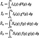
Подпись: where

m = f m(y)P(y) dy


Jo

FLUTTER OF A THREE-DIMENSIONAL WING


Pap =| {РрШсрІУ) ~ b(y) + K(y)s 4>(y)g(y) dy

The symbol / denotes the semispan of the wing, and 1Ъ /2 denote, respec­tively, the spanwise locations of the inner and outer ends of the aileron. m, Ia, etc., are called the generalized mass, generalized mass moment of inertia, etc.

The strain energy stored in the wing is

The Lagrange’s equations of motion are

d (3T ЭК dt Эqj + dqt *

Using Eqs. 6 and 13, we obtain the equations of motion:

m h + BJi + Sp(i + mcofh = Qh BXR + /хЙ + Papfi + 7«W«2* = Qa Bp h + Pxpoi + Ір’/І + Ip<op2fi = Qp

FLUTTER OF A THREE-DIMENSIONAL WING

FLUTTER OF A THREE-DIMENSIONAL WING

(10)


and Kp is the torsional “spring constant” of the aileron control system. As in § 6.9, the generalized spring constants Kh, Ka, Kp may be replaced by the corresponding “uncoupled” free-vibration frequencies. Thus, if toh is the uncoupled free vibration frequency in the h degree of freedom, we have


Kh = mojf


(И)


Similarly,


Ka = W, Kf = faf


Hence, Eq. 9 may be written as

V = inwfh% +


(13)


(<]i = к Д)


FLUTTER OF A THREE-DIMENSIONAL WINGFLUTTER OF A THREE-DIMENSIONAL WINGFLUTTER OF A THREE-DIMENSIONAL WING

At the critical flutter condition, the wing motion is simple harmonic. We may write, in complex representation, (§ 1.8)

h{t) = h^ ЦІ) = /3(0 – (15)

Such a simple-harmonic solution is possible if we assume that the ampli­tude of oscillation is very small, because then the generalized forces Qh, Qa, Qp are linear functions of ft, a, /3, and Eqs. 14 become a system of linear equations. A solution of the form of Eqs. 15, with h0, a0, /?0 complex valued, is admissible for such a system of equations. When we substitute Eqs. 15 into Eqs. 14 and canceling the factor еш, the time-free equations of motion are obtained. If, in these equations, the elastic-

restoring-force terms are multiplied by factors of the form (1 + ig) to

represent the structural damping forces, in phase with the velocity and opposing the motion (see § 6.9), we obtain

— mmh + Д*a + 8ф) – f (1 + ig^rrtmff = Qh

— <x>Sji + 7aa + Дхд/З) + (1 + igffojfd. = Qol (16)

— m2(Sph + Дцз& + їф) + (1 + igp)Ipa>p2fi — Qp

The generalized forces Qh, Qx, Qfl must be computed. The aero­dynamic forces and moments at a section at у are given by Eqs. 15 of §6.10. For a three-dimensional wing, however, the coefficients Lh, La, Mh, Ma, etc., are not only functions of the Mach number M and the reduced frequency k, but also of the aspect ratio of the wing, the wing geometry (taper ratio, sweep angle, etc.), the wing deflection mode (the nodal-line location and the shape of the deflection curve), as well as the spanwise location y. To simplify the calculation, the strip assumption is often introduced, which states that the aerodynamic force acting at any section is the same as if that section were a part of a two-dimensional wing. Furthermore, the induced downwash due to trailing vortices is neglected. Therefore, the coefficients Lh, La, etc., are given by the same tables as those for the two-dimensional case.

Since к = ab/U is proportional to the semichord b, it generally varies across the span. If a particular cross section of the wing is defined as a reference cross section, of which the semichord and the corresponding “reference” reduced frequency are denoted by br and kr — mbfU, respec­tively, then any other cross section with a chord b(y) will have the reduced frequency

FLUTTER OF A THREE-DIMENSIONAL WING

The coefficients Ьъ, Lx, etc., being functions of k, can thereafter be com­prehended as functions of y, with the reference reduced frequency kr as a parameter.

The generalized force Qh for the oscillating bending motion is obtained by considering the virtual work due to a variation of the generalized coordinate 8h, which corresponds to a virtual displacement 8hf(y). This gives*

Q„(t)bh = – J’le. a.fy, t)8hf(y)dy

i. e.,

Qi,(t) = – f LKJ1(y, t)f(y)dy (17)

J 0

Similarly,

Qa(t) = J Мея(у, t) ф{у) dy, Qp(t) = ТшреІУ, t)g(y) dy (18)

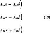
Substituting Eqs. 15 of § 6.10 into the above equations, we obtain
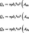
FLUTTER OF A THREE-DIMENSIONAL WINGFLUTTER OF A THREE-DIMENSIONAL WINGR

* In Eq. 7 of § 1.6, the generalized coordinate qn and the generalized force Q„ are real valued; then the virtual work 6W is simply S Q„8q„ If the motion q„ is sinusoidal, Q„ is also sinusoidal, and qn, Q„ can be represented by complex representations. As is shown in Eq. 5a of § 5.4, a simple multiplication Q„ 6qn does not represent the virtual work. However, it is readily shown (Nilsson and Langefors7-50) that the sum of the product of Qn with the complex conjugate of 6q„

SfV 8q*n

represents a complex invariant with respect to coordinate transformation from the physical (real) coordinates to the generalized coordinates. The real and imaginary parts of &Wcan be interpreted physically as the “active” and “reactive” energy.

Let qn = q„oeimt, where qn0 is a real number, and Qn = (QnR + iQni)el°d then

8W= (S„r + гQ„i) ■ 6qn0

This equation can be used to compute the proper form of the generalized force Q„, since the complex invariant 6 W can be calculated in the rectangular Cartesian coordin­ates. Equations 17 and 18 are based on this argument.

where br is the semichord at a reference section, and

Ahh = Jo (j) Piy) Lh(y) dy A* =Jo f(y) ф(у) [-£» ~ (^ + dy An =| (j) f(y)g(y) An ~ A ~ e?)Lz] dy Ah = Jo f{y) m Mh ~ dy

A« =£(^-)4 ФЧУ) Ma – (I + efc) (A + Mh)

+ A dy

Подпись:An =| ^ Ф(у) g(y) мр – (^ + Lp – (cp – ep)Mz

+ (cp – ep) [X – + Lzj dy

(J+ e*) (Cfi ~

Подпись: їде FLUTTER OF A THREE-DIMENSIONAL WING

Ah =f’(^)3/(2/) g(y)[Th – {Cp – ep)Ph] dy Aa =| Ф(У) g(y) A – (cp – ep)PX — Q-+ a)j Th

Combining Eqs. 16 and 19, we obtain the equations of motion at the critical flutter condition. Comparing these equations with Eqs. 19 of § 6.10, we see that they are of the same form, except that the mass, moment of inertia, and aerodynamic coefficients must all be interpreted as the generalized quantities. The solution of the final determinantal equation can be obtained by the same methods used in § 6.11.

We have assumed in the above analysis (1) the existence of an unswept straight elastic axis, and (2) the strip assumption for aerodynamic action. Let us consider now cases in which these assumptions must be relaxed.

If the structure does not behave like a simple beam (in the sense that the formulas listed in § 1.1 hold), but its chordwise sections can be regarded as rigid, then the simplest procedure is to choose any convenient straight line as a reference line; the vertical deflection of a point on this line may be denoted by h, and the rotations of a cross section normal to the reference line in its own plane may be denoted by a. The expressions of the kinetic energy T and the generalized forces Qh, Qa, etc., take the same form as those presented above, except that the word “elastic axis” must now be interpreted as the “reference line.” The strain energy, however, cannot be obtained from Eq. 8 or 13, whose validity depends on the concepts of shear center and elastic axis. Nevertheless, from the general principles of elasticity, we can conclude that the strain energy must be expressible as a quadratic function of elastic displacements. (By Castigliano’s theorem the elastic displacements are linearly proportional to the loading only if the strain energy expression is quadratic.) In the present case, the strain energy is a quadratic function of h, a, and /5. A practical way of deriving such a strain energy expression is to use the stiffness influence coefficients, as shown in Eq. 7 of § 1.4.

For a monocoque wing with cutouts or with restrained cross-sectional warping, it is necessary to solve the shear lag problem in order to obtain the “flexibility” influence coefficients, from which the stiffness influence coefficients can be derived by a matrix inversion. If a structure is avail­able for testing, the influence coefficients can be measured directly. The use of stiffness influence coefficients avoids differentiation of the assumed semirigid modes in computing the strain energy, and thus is favorable for numerical accuracy.

If the chordwise sections cannot be regarded as rigid, the deflection surface must be described by a continuous function in more than one dimension. For example, if a wing occupies a region on the (x, y) plane, the deflection w(x, y; t) may be expressed as

w(x, y, t)= q{t)f(x, y) + q2(t)f2(x, «/) + •••+ qn(t)fn(x, y)

where fx(x, y), f2(x, y), etc., are the modes on which the generalized co­ordinates qx, q2, ■ ■ •, etc., are defined. The calculation of the kinetic energy presents no difficulty. The strain energy can be expressed in terms of stiffness-influence coefficients. The aerodynamic force, how­ever, would have to be calculated from the general theory of oscillating airfoils.

When the strip assumption for aerodynamic action is relaxed, it is necessary to solve the three-dimensional oscillating-airfoil problem for the oscillation mode of each generalized coordinate. This can be done in principle, but so far no convenient table of aerodynamic coefficients

exists. For low-aspect ratio wings, the wing-fuselage interference effect can also become important.

It is evident that in all cases Lagrange’s equations reduce to a set of linear equations in the generalized coordinates, and the methods of § 6.11 are sufficient to derive the flutter conditions.

ENGINEERING FLUTTER ANALYSIS AND. STRUCTURAL DESIGN

Extension of flutter analysis of the preceding chapter to three-dimen­sional structure is straightforward. In § 7.1, a practical approach, based on generalized coordinates, will be outlined in greater detail. The underlying principles for the selection of generalized coordinates is discussed in § 7.2. The limitations of the theory are then pointed out in § 7.3. Some general remarks on the control and prevention of flutter are presented in § 7.4.

Flutter analysis should be comprehensive so that no factor is overlooked. We know many instances in which the crucial factors that caused com­mercial disaster or loss of lives were so hidden that they were forgotten. One fine turboprop plane had several disastrous flutter failures because of an ignorance of the propeller yawing effect (oscillatory aerodynamic force acting on the propeller in a direction perpendicular to the axis of the propeller). One high performance fighter development lost many millions of dollars because of the use of a rubbing block (for dry friction) in the control system. A famous company which made very extensive flutter analysis in the course of development of an airplane was met with flutter failure because the engineers employed the same simplifying assumptions in building the mathematical model for analysis and the wind tunnel model for testing; in which case the confidence derived from the agreement between theory and experiment was meaningless with regard to the prototype.

On the other hand, the varied conditions in the service of the aircraft must be considered. Icing, fuel displacement, minor structural damages, may cause flutter. One small private airplane crashed because of accumu­lation of dust in the wing.

Safety can be purchased only with exhaustive care!