Category An Introduction to THE THEORY OF. AEROELASTICITY

TWISTING OF PROPELLER BLADES

Divergence has an important bearing on many phases of the aeroelastic stability of propellers, not only because the steady-state instability in itself must be avoided, but also because of its close relationship to flutter. It was shown by Theodorsen and Regier4,36 that in some cases the blade simply twists to the stalling angle and initiates stall flutter when the speed is too close to the divergence speed. Thus the problem of pre­dicting propeller flutter is resolved primarily into the calculation of the speed at which the propeller will stall due to its aeroelastic twist, and the critical-divergence speed becomes a convenient criterion.

The divergence of propellers can be analyzed by the same methods as those exposed before, except that the effect of the centrifugal force must be added.

In a good propeller design, large bending stresses are avoided by making the normal component of the centrifugal force balance approximately the aerodynamic lift. Hence, it is a fair approximation to assume that the twisting moment acting on the blade consists in a couple formed by a lift force and a centrifugal-force component which is assumed equal to the lift.

Consider a representative se. ction of the propeller (Fig. 4.12). Let c be

the length of the chord, and xc be the distance from the center of mass to the leading edge. Then the twisting moment is

(Lift) • c(x — I)

This is balanced by the elastic moment. Let К be the torsional stiffness of the representative section defined as in Eq. 5 of § 3.3; then the equili­brium condition is

Кв = scx — )qa(xr + в — a0) (1)

where ar is the angle of attack of the section if the blade is perfectly rigid, в the angle of twist due to elasticity, oc0 the angle of attack for which there is no twist (to be explained later), q the dynamic pressure of the relative airstream, у a representative length of propeller blade, and a the lift-curve slope of the section.

The condition of divergence of the blade is that в -> со; i. e.,

в

*, + в — a0

The critical-divergence speed is then given by

Подпись: (2)К

TWISTING OF PROPELLER BLADES Подпись: (3)

Uv ~~ sc*a{x – 1)

From this equation, we see that the angle of twist increases rapidly when Ц f7div*

The conventional propeller design is based on the assumption of perfectly rigid blades. The design condition is stated in terms of ar or the corresponding lift coefficient CLr. The true lift coefficient CL of the elastic propeller is related to CLr by the relation

CL — CLr + ав (4)

The angle of attack for zero twist a0 can be calculated from the equi­librium of aerodynamic force and the centrifugal force. In the no-twist condition, the couple of the centrifugal force and the lift just balances the aerodynamic moment about the aerodynamic center, for which the moment coefficient is C:m. Hence, the equilibrium condition is

Cjiro + acr. Q(x i) = 0 (5)

provided that the angles a0 and ar are measured from the zero-lift line. Combining Eqs. 3 and 5 with 4, we obtain

TWISTING OF PROPELLER BLADES(6)

(7)

Подпись: LI~ Подпись: C
TWISTING OF PROPELLER BLADES Подпись: (8)

The second term of the right-hand side of Eq. 7 is the increase in lift coefficient due to the elastic twist of the blade. This increase will be zero, and the blade will not be twisted, if the design lift coefficient is

This is the ideal design lift coefficient given by Theodorsen and Regier. For the Clark-Г airfoil with center of gravity at 44 per cent and CM0 = — 0.07, CLI is 0.37. In this case the angle of attack at zero elastic twist is not very far from the optimum angle of attack of the Clark – Y airfoil, which is at CL — 0.40. Since operating a blade at CLI delays the stall, and thus causes an increase in the flutter speed, it is desirable to operate the propeller at the ideal angle of attack.

In using Eq. 2 to determine the divergence speed, the choice of the radius of the representative sections is open to question. Usually the 80 per cent radius section is taken as the representative section, at which L, c, x, and the corresponding stiffness К are measured. A more rational basis is to use Lagrange’s equations or a method of successive approxima­

tion, similar to those of §§ 3.4, and 3.5. The arbitrariness of choosing a representative section can thus be avoided.

The closeness of the elastic axis, the inertia axis, and the line of aero­dynamic centers of practical propeller or helicopter blades makes such blades inherently strong against flutter. An exact flutter analysis, how­ever, must consider the nonuniform flow condition across the span, the centrifugal force, and the Coriolis force, and is not simple. See papers by Morris, Rosenberg, Duncan, Turner, etc., listed in the bibliography of Chapter 7.

THE EFFECT OF ELASTIC DEFORMATION ON THE STATIC LONGITUDINAL STABILITY OF AN AIRPLANE

The static longitudinal stability is measured by the derivative dCM/dCL at the symmetrical level flight condition, where CL is the total lift coeffi­cient and CM is the coefficient of the pitching moment about the airplane center of gravity. An airplane is statically stable when 5CMjc>CL is negative. In power-off condition and for the rearmost center of gravity location, a value of — ЪСм/дСь from 0.10 to 0.15 usually leads to satis­factory results. A study of the pitching moment about the center of
gravity in steady flight is a very complex one when the effects of power, component interference, and free controls are taken into account. How­ever, a large amount of experimental data has been gathered in the past, and the determination of the dCMjdCL derivative for a rigid airplane offers no serious difficulty, even in the most complicated cases.[12]

If the airplane is not rigid, the static longitudinal stability derivative will be affected by the elastic bending of the fuselage and the twisting of the wing and tail surfaces. Let us consider, as an example, an airplane with unswept wing and tail and having the control stick fixed (i. e., elevator locked). To account for the effect of elastic deformatioft approximately, we shall take a reference section of the wing and a reference section of the tail determined in the same manner as in § 4.6.t Let the angles of attack of the wing and the tail be a„j0 and at0 respectively, when the total lift coefficient CL vanishes. If the fuselage is now rotated through an angle a about the airplane center of gravity, the new angle of attack of the wing will be (аю0 – far 9W), and that of the tail, (a(0 + a – f 0t); 6W, 6t being the elastic twisting angles of the wing and tail, respectively. 6t can be found from the equations of § 4.6. In the case of a locked elevator, we may regard the tail as a full-chord elevator and put

m = 0, a2 = at, /3 = а + а<0 from which (1)

A=qtlqm v, B=-A

To derive an expression that gives the total angle of twist of the tail as a result of the rotation a, let us add a term CMotqtStct to the right-hand side of the expression for Mt in Eq. 7 of § 4.6, to represent the moment about the aerodynamic center at zero lift. Substituting Lt and Mt from Eqs. 7 of § 4.6 into the relation

Подпись:Подпись: ■ («• + <*«)THE EFFECT OF ELASTIC DEFORMATION ON THE STATIC LONGITUDINAL STABILITY OF AN AIRPLANE(2)

THE EFFECT OF ELASTIC DEFORMATION ON THE STATIC LONGITUDINAL STABILITY OF AN AIRPLANE

and solving for 0t, we obtain

where K3 denotes the spring constant for wing twisting with respect to airplane c. g., K3 is the torque required to act at the wing-reference section to produce a change of angle of attack of 1 radian at the wing-reference section with respect to a fuselage that is clamped at the c. g. Equation 4 is a slightly more general expression than Eq. 7 of § 3.1.

Neglecting the tail lift in comparison with the wing lift, we obtain the total lift coefficient of the airplane from Eq. 4:

С/, —■ aw(ctw0 + a + 8.J


кя


a •


(5)


Aw0


THE EFFECT OF ELASTIC DEFORMATION ON THE STATIC LONGITUDINAL STABILITY OF AN AIRPLANE

THE EFFECT OF ELASTIC DEFORMATION ON THE STATIC LONGITUDINAL STABILITY OF AN AIRPLANE

Solving Eq. 5 for a, and substituting into

CLt = a I a(0 + a + 01)

we obtain

THE EFFECT OF ELASTIC DEFORMATION ON THE STATIC LONGITUDINAL STABILITY OF AN AIRPLANE

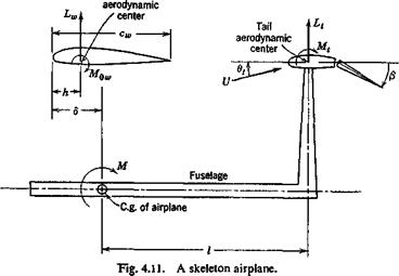
If the airplane were perfectly rigid, then qw alv and qt div are infinitely large and CLi and Cm are obtained from Eqs. 6 by putting all terms involving qw div, qt div, K2, and K3 to be zero. Therefore the change of CLt and Cm due to the elastic deformation of the airplane can be easily calculated. The total pitching moment about the airplane c. g. is, clearly from Fig. 4.11,

M = Lw(d – h) + M3W ~ Ltl + Mt (7)

or, in coefficients form,

THE EFFECT OF ELASTIC DEFORMATION ON THE STATIC LONGITUDINAL STABILITY OF AN AIRPLANE

(8)


‘M


THE EFFECT OF ELASTIC DEFORMATION ON THE STATIC LONGITUDINAL STABILITY OF AN AIRPLANE

where 8 is the distance of the airplane c. g. behind the wing leading edge, h is the location of wing aerodynamic center behind the wing leading edge, and M0w is the aerodynamic moment of the wing about its aerodynamic center. Hence, the change of the static longitudinal stability derivative due to the elastic deformation of the airplane is

А = 1 л /ЭСЦ CtqtS idCMt

3CL) cw qSw bcLJ cwqSw 5CL J

Hence,

The static longitudinal-stability derivative of an elastic airplane is therefore

(13)

From Eq. 12 it is seen that, for an aeroelastically stable airplane, the effect of elastic deformation on the static longitudinal-stability derivative depends on the relative magnitude of the divergence dynamic pressures of the wing and tail. For instance, if the wing is so rigid that |?waiv| A |<fcaiv|> while the fuselage and tail are such that qt div is positive, then a strong stabilizing effect will occur as q approaches qt div. On the other hand, if qw div is nearly equal to qtdiv or, more precisely, if qw <nJqt div = q/qt then the effect of the elastic deformation on the static longitudinal stability disappears.

The same method can be used to study the change of stabilizer “trim” due to elastic deformation of the airplane. The trim problem is, for high-speed airplanes, one of the most important factors in tail design.

TAIL EFFICIENCY

Two aspects of the effect of elastic deformation of the horizontal tail and fuselage will be considered: the elastic efficiency of the horizontal tail and the static longitudinal stability of the airplane. The analysis will be made in an approximate manner. Only unswept wings and tails will be considered.

When an elevator angle changes, the pitching moment about the air­plane center of gravity (c. g.) changes. If, originally, the airplane were in the condition of rectilinear symmetric steady flight, then the change of pitching moment induced by the elevator deflection would cause the air­plane to pitch, and disturbed motion would ensue. In order to study the efficiency of the tail alone, however, it is more convenient to consider the unbalanced pitching moment, instead of the dynamics of the airplane as a whole. For this purpose, the airplane shall be assumed to be held fixed, against any disturbed motion, at the c. g. of the airplane. The wing and the structures in front of the c. g. shall not be disturbed. In this fictitious condition, the pitching moment (positive if it tends to increase the angle of attack) contributed by the horizontal tail surfaces, about the c. g., is

M = – lLt + Mt (1)

where Lt is the resultant lift of the tail, acting through the tail aerodynamic center; Mt is the pitching moment about the tail aerodynamic center; and l is the distance from the airplane c. g. to the resultant tail lift Lt. Generally, it is sufficiently accurate to assume Lt as normal to the fuselage reference axis, and to neglect the horizontal component of the aerodynamic forces. Then l is a constant independent of the angle of attack.

TAIL EFFICIENCY Подпись: (2)
TAIL EFFICIENCY TAIL EFFICIENCY

It is convenient to express the pitching moment about airplane c. g. by a moment coefficient based on wing area and wing chord; and L, and Mt by coefficients based on tail area and tail chord. Let ( )ш and ( )t denote quantities relating to wing and tail, respectively. Let q denote the dynamic pressure, S the area, c the chord length. We define

The bar over cw and ct indicates mean aerodynamic chords. qt denotes the dynamic pressure at the tail region, which, due to wing-fuselage interference and engine slip stream, may be slightly different from the free-stream dynamic pressure q.

A measure of the tail efficiency is the rate of change of the pitching – moment coefficient with elevator deflection, dCMjd/3, ft being the (sym­metric) elevator deflection angle (positive if deflected downward). Owing to the elastic deformation of the tail and the fuselage, the derivative ЗС, И/Э/3 for a real airplane is smaller than that of a rigid airplane. The ratio

Подпись: (3)ЗСм I /ЭСМ

эpiw ;rigid

+ /дч

Э/S qSw cw dp cw dp )

To compute the derivatives dCLtjdp, dCMt/dp, it is necessary to con­sider the elastic deformation of the airplane. The airplane structure can be represented by a skeleton system of beams as shown in Fig. 4.11. The tail angles of attack shall be represented by a characteristic number 0, measured at a reference section located at a spanwise coordinate rjt. If Wing

TAIL EFFICIENCY

the tail angle-ofiattack distribution is described by 60f(y), у being the spanwise coordinate, then щ may be defined according to the following equation:

= % f(Vt) = sr f ЛУ) Ф) dy (5)

where st is the tail semispan, and St is the tail area. Hence 6t is a weighted average of the tail angle of attack. If a semirigid mode of the tail twisting f(y) is assumed, rt can be evaluated at once. Generally it lies at 2/3 to 3/4 semispan outboard from the fuselage.

The elastic property of the tail and fuselage may be described by two stiffness-influence coefficients Кг and K2 defined as follows. Let Kt be the total lift force (with KJ2 acting at each of the reference sections on the two halves of the horizontal tail) that is required to act at the tail aero­dynamic center to produce a rotation of 1 radian at the tail reference

section,* with the fuselage assumed clamped at the airplane c. g. Let K2 be the total pitching moment (with KJ2 acting at each reference section) that is required to act at the tail reference sections to produce the same rotation. Then the total change of the tail angle of attack is

Подпись: Mj *2 TAIL EFFICIENCY(6)

To evaluate the derivatives involved in Eq. 4, it is only necessary to consider a small deflection angle Д/S. In the following, the quantities /8, 0t, Lt, and Mt will denote the changes corresponding to Д/S, and the symbol Д will be omitted. Let us assume that the strip assumption may be used and that the lift-curve slope at and the derivatives dCLt/cfS == аъ 8CMt/df3 з – m of the tail airfoil section be evaluated at the steady flight conditions. Then, if 6t is defined as in Eq. 5, we have Lt = qtSt(atOt + аф)

Mt = – m(SqtStct

where**

TAIL EFFICIENCY Подпись: (8) (9)

Combining Eqs. 6 and 7, we obtain

From Eqs. 7 and 8, and according to the definitions 2, we derive

*cLt

Э/3

A

а*в +

«2

3CMt

Э/3

= —

m

(10)

Hence,

from Eq

• 4,

3CM

Г /

I A,

, et

(П)

Э/3

qSw

A

V’-B + ‘V

+ rr

m

If the

airplane

were perfectly

rigid, then Kx

= K2

=

00,

A — 0, and

B= 1,

so

(3CM

Г l

тсЛ

(12)

Э/3

‘ rigid

qSw

~ <?2

.cw

Cw .

* Actually we are interested only in small deflections, so the linearity of the structural property can be assumed.

**If the aerodynamic moment of the elevator is resisted by a control stick, the quantity m in A, Eq. 9 and Eq. 16 infra, should be replaced by 8Смі/8[} — SCm/Sf} where Chi is the hinge moment coefficient of the elevator based on the tail area and tail chord. Elsewhere no change is needed.

The elastic efficiency of the elevator is therefore

І

/

‘pcy

Э0 у

1 , Al l / mcA-1 | – 1 + ГГв2 + – J-)

rigid ■Ui"w *

(13)

(if et<l)

E #2

(14)

We may define, in analogy with the wing divergence, the critical diver­gence speed of the horizontal tail at which an infinitesimal change in /3 induces a large tail twist. According to Eq. 8 this occurs when В = 0,

i. e., when

Подпись: (15)Подпись:A

Stat

If K± is negative, then qt div given by Eq. 15 has no physical meaning, but is merely a parameter showing that the tail is stable.

*Ї_ _£*_

Stct atm

TAIL EFFICIENCY Подпись: (16)

We may also define a critical horizontal tail-control reversal speed at which a change of elevator angle produces no change in the pitching moment about the airplane c. g. This occurs when the tail efficiency becomes zero. Using the approximate formula 14, we obtain, at the reversal speed,

Note that qtiev is independent of Kb because at the reversal speed the tail lift due to elevator deflection vanishes. Using Eqs. 15 and 16, we may write

Elastic efficiency of elevator = ;——– -*(–■—v (17)

1 – qttit aw

SWEPT WINGS

For highly swept wings it is necessary to use Weissinger’s method to determine the aerodynamic loading. For approximate solutions, how­ever, the modified Schrenk’s method4-53 given by Pope and Haney offers great simplification and fair accuracy. In many occasions, the strip theory is sufficiently accurate.

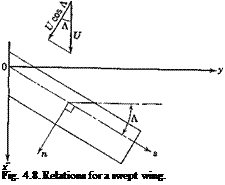
Besides the change in lift curve slope as shown by Eqs. 6, 7, 8 and 16 of § 4.3, swept wings differ aeroelastically from normal wings in the effective angle of attack due to elastic deformation (Eq. 5, § 4.4):

Подпись: a(e) = в cos ЛПодпись: (1)3w. ,

sin Л

Bs

where 9wjds is the slope of the deflection curve in the spanwise direction. Hence, whenever Л Ф 0 (Fig. 4.8), the effective angle of attack, and hence the aerodynamic loading, depends on the bending deflection as well as on the torsional deflection. The effect of the bending deflection can be seen qualitatively as follows. For a sweptback wing (Л > 0), an increase in angle of attack a(r) yields a positive slope 9wjds and hence reduces a(e). This, together with the reduction of the lift curve slope due to Л, means that the wing is not so easily twisted as a normal wing. Thus the sweep – back increases the torsional stability. Hence, the divergence speed is increased by sweepback. For a sweptforward wing (Л < 0), the effect of bending tends to decrease the divergence speed, whereas the reduction of lift curve slope tends to increase it. Generally, the divergence speed is decreased by sweepforward.

On the other hand, for a positive (downward) aileron deflection, dwjds is again positive and a(e) is again reduced if Л > 0, and increased if Л < 0. Accordingly, the effect of bending has a tendency to make the aileron less or more effective according to Л > 0 or Л < 0, respectively. In other words, the effect of bending tends to have the aileron efficiency and the aileron reversal speed reduced by sweepback and increased by sweepforward. Whether a wing’s reversal speed would actually be reduced by sweepback or not depends on the balance between several opposing influences, and a careful analysis is required.

For a cantilever wing with the wing root fixed in space, dw/ds vanishes at the wing root because of the clamping boundary conditions. It increases to a maximum toward the wing tip. Hence, the aforesaid effect of sweep is more seriously felt near the wing tip. It is therefore obvious that, when the pitching angle a(r) of the airplane is increased, the effect of sweepback is to unload the wing tips, and to cause the center of pressure of the wing to move forward. For a sweptforward wing, the load near the wing tip is increased by the elastic bending, and the center of pressure moves forward towards the wing tips. This shift of wing center of pressure has very important effect on the airplane stability.

Detailed presentation of the effects of sweepback and sweepforward can be found in Refs. 4.6, 4.10, 4.26-35.

THE EFFECT OF ELASTIC DEFORMATION ON THE LIFT DISTRIBUTION

For a wing of small aspect ratio, or arbitrary planform, or with large cutouts, or subject to serious effect of warping restraint at the wing root, it is necessary to consider the entire deflection surface of the wing (instead of assuming rigid chordwise sections), and to compute the lift distribution by a lifting-surface theory. In this case the problem of determining the effect of the elastic deformation on the lift distribution can be formulated

и

THE EFFECT OF ELASTIC DEFORMATION ON THE LIFT DISTRIBUTION

A-A

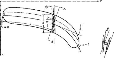
Fig. 4.7. A slender wing.

by means of influence functions into integral equations of two independent variables (involving double integrals). In most practical cases, however, the warping of the chordwise sections is not of great importance, and reasonable accuracy can be obtained by considering the deformation pattern at each chordwise section as characterized by a deflection at a reference point and a rotation in the chordwise section about that point.

For a wing other than a normal simple beam, the concept of elastic axis loses its simplicity, and it becomes more straightforward to define the wing deformation with respect to an arbitrary reference line. As re­marked in § 3.2, when an arbitrary reference line is used, two influence functions are required to specify the wing rotation and two others to specify the wing deflection. As an example, consider a wing of large aspect ratio whose cross sections normal to a reference line may be

assumed rigid. Let s be the distance measured from an origin along the reference line (see Fig. 4.7). Let w(j) be the deflection at a point s on the reference line, normal to the plane of the wing (the wing is assumed to be planar, and the displacement in the plane of the wing is assumed to be negligible), and let 6(s) be the angle of twist of a normal cross section at s about the reference line. In the lift-distribution problem, the slope dw/ds, rather than w itself, is of importance. The elastic property of the wing can be characterized by the following influence functions:

Fi(s, о),

. . dw giving —

ds

at s

due to a unit force at о

F2(s, o),

giving в

at 5

due to a unit force at a

Hi(s, <r),

. . dw giving-

at 5

due to a unit external twisting moment at о

H2(s, o),

giving в

at s

due to a unit external twisting moment at о

By an external twisting moment at the point a is meant a couple whose vector is tangent to the reference line at the point o. If there acts a unit couple at a whose vector is perpendicular to the reference line at a, which will be referred to as a unit external bending moment, the deflection surface can be obtained from the following influence functions:*

SFjCs, o) giving dw/ds at s due to a unit external bending moment do ’ at о

giving в at 5 due to a unit external bending moment at о do

In defining these influence functions, the structure is assumed to be rigidly supported in a manner appropriate to the particular problem under consideration (cf. footnote, p. 19). In order to define the positive senses of-w, 6 etc., we define a set of local orthogonal coordinates (n, s), with s tangent to the reference axis and n normal to it; n is to s as x is to у axis (see Figs. 4.7 and 4.8). The senses of the force and deflection agree, and

* This can be easily verified by considering a bending couple as the limit of a pair of equal and opposite forces, the magnitude of which increases as the distance between them decreases, in such a way that a unit moment is maintained. Thus the slope 3w/3s at a point s due to a force M/Aa acting at a – f Дег/2 and another force — M/Ao at о — Ao/2 is

Подпись:Подпись: AcrTHE EFFECT OF ELASTIC DEFORMATION ON THE LIFT DISTRIBUTION+

The limit as Atr 0 gives dw/ds = MdFJda, which verifies the statement.

are positive in the positive direction of the z axis (xyz a right-hand system). The bending moment and the twisting moment are positive when their vectors are in the positive directions of n and s, respectively.

Let the external loading be resolved into forces acting on the reference line and bending and twisting moments about it. If we denote the normal external load per unit length on the reference line by f(s), the distributed external bending moment per unit length by m(s), and the distributed external twisting moment per unit length by t(s), we have

^ (J) = f Fi(*, a)f(a) da + f У1 ^ m(a) da + Г Нг {s, a) t(a) da (1) ds Jo Jo со Jo

Cl Cl 3F (s Cl

6(s) = Ffs, a) f(a) da + —2 ’ ’ m(a) da + Нг (s, a) t(a) da (2)

Jo Jo da Jo

where the integration covers the entire length of the wing.

Consider now the lift problem. The angle of attack at any section s, denoted by v.(s), can be expressed as

a(^) = a<r) + a(e) (3)

where a(r) denotes the angle of attack of the airfoil if it were perfectly rigid’, and a<e) indicates the change due to elastic deformation. a.(s) is supposed to be measured in the flight direction and does not include induc­tion effects of the lift.

For a given <x.(s), the aerodynamic force and moment distribution can be determined by the methods mentioned in § 4.3. For a given lift and moment distribution, the elastic deformation can be computed according to Eqs. 1 and 2. The elastic deformation in turn determines a.(s). Thus the nature of an aeroelastic system as a feedback system is clearly seen.

It is natural to apply a process of successive approximation to find the effect of elastic deformation on the lift distribution, especially when the speed of flight is considerably lower than the divergence speed of the wing. In this process we start from the angle-of-attack distribution vSr)(s) of a rigid wing, find first the lift and moment distribution corresponding to txlr,(s), and then the elastic deformation a<e,(s). Next we determine lift and moment distribution corresponding to a(s) = x, r> + a(e> computed in the first cycle and determine the elastic deformation x(e)(s) again. If, by repeating the process, we arrive at a limiting function a(s), then that limiting function is the equilibrium angle-of-attack distribution of the elastic wing corresponding to a(r>(s).

Because of its importance, we shall examine the problem in greater detail and give a numerical example below.*

* The treatment follows essentially that of Pai and Sears.4-35

Equations of Equilibrium. The aerodynamic forces acting on a deformed wing can be expressed in terms of “local” lift and moment coefficients, which are defined by considering the lift and moment acting on an elementary strip of small width dy parallel to the x axis (see Fig. 4.7). The length of this strip is the chord length c measured in the free-stream direction. The lift force on the strip is qC, c dy, and the moment about the aerodynamic center of this strip is qCmc2 dy. We shall assume that the drag force is negligible and that the force normal to the wing is equal to the lift force. Let the distance between the aerodynamic center and the reference line be ec, also measured in the free-stream direction, and taken as positive if the latter lies behind the former. Then the moment about a point on the reference line due to forces on the elementary strip is qCxec2 dy + qCmc2 dy. The vector of this moment is parallel to the у axis, and can be resolved into an external bending moment — q(Cte – f – Cm)c2 sin A dy and an external twisting moment q(C, e + Cm)c2 dy cos Л about the reference line, where Л denotes the sweepback angle at the point ^ as shown in Fig. 4.7.

THE EFFECT OF ELASTIC DEFORMATION ON THE LIFT DISTRIBUTION

Let w and Cj be positive when the wing tends to deflect upward. Let в and the twisting moment be positive when the wing tends to increase the angle of attack. Since only the aerodynamic loads need be considered, we have, replacing dy by cos Л da, and using Eqs. 1 and 2:

A similar equation for 6(s) is obtained by replacing Fv H1 by F2 and H2, respectively, on the right-hand side.

The elastic angle of attack a(e) is given by

Подпись: (5)x{e) = в cos Л — — sin Л ds

THE EFFECT OF ELASTIC DEFORMATION ON THE LIFT DISTRIBUTION

which can be derived as follows: Let the wing-deflection surface be denoted by w(x, y); then the slope in the x direction is

Подпись: cos Л, and —- = — в dn Подпись: (7)
THE EFFECT OF ELASTIC DEFORMATION ON THE LIFT DISTRIBUTION

where (^, n) are local orthogonal coordinates in directions parallel and perpendicular to the reference axis (Fig. 4.8). But

Hence, Eq. 5, because a(e) is equal to the negative of the slope dw/dx in the particular coordinate system chosen.

Подпись: X Fig. 4.8. Relations for a swept wing.

The determination of Ct(s) and Cm(s) from a(.s) = a(r) + a(<!) is a problem in aerodynamics. When a definite theory is adopted so that a relation

between a(s) and Ct and Cm is known, that relation, in conjunction with Eqs. 4 and 5, determines the functions a(j), Ct(s), and Cm(s).

Подпись: 'o

As an example, assume that Л is small so that Prandtl’s lifting-line, theory can be used, a and Ct are therefore related by Eq. 1 of § 4.3. Combining that equation with Eqs. 4 and 5, we obtain the integral equation for C,:

Подпись:

Подпись: [CM e(a) + Cm(a)]ca) rfa)

~ a{r)(s) + ? [F2(s, a) cos A(s) — Fx(s, a) sin Л(^)] Сг(а) c(a)

THE EFFECT OF ELASTIC DEFORMATION ON THE LIFT DISTRIBUTION

fo.

(8)

where y, t] are, respectively, the projections of s, a on the у axis, a0(s) is the two-dimensional lift-curve slope at s, and the integrals are taken over

the entire span. The integral on the left hand side of the equation is a Cauchy integral.

Equation 8 can be solved by the method of successive approxima­tion,312 but the most expedient method for practical application is to reduce it into a matrix equation (§ 3.7). If the approximation of the “strip” theory can be accepted, the second term, which is a singular integral, drops out, whereas a0 is replaced by the over-all lift-curve slope of the wing.

Reduction to Matrix Equations. For a numerical solution, a, Ci( Cm at a number of spanwise coordinates are sought. It is best to approximate the integral equation by a matrix equation.4-20’4 35 The column matrix {cCij can be regarded, of course, as a product of a square matrix c with the column matrix Сг, c being a diagonal matrix with the fth element in the principle diagonal equal to the chord length ct at s = st.

Let a(s), Ct(s), and cCt(s) be represented by column matrices а, Сг, and cC, with elements a1; oc2, • • a„; Ca, C!2> • • •, Cln, and сгСп, c2C!2, • • •, cnCln specified at s = q, q, • • •, sn, respectively. The relation between a and Сг is as follows:

1. Strip Theory.

Сг = aa (9)

where a is the lift-curve slope of the wing corrected for the aspect ratio and planform.

2.

Подпись: m = 1
Подпись: sin my> — a0 (a Подпись: sin ту) I sin y) I Подпись: (10)

Lifting-Line Theory. Glauert’s Solution. Prandtl’s lifting-line equa­tion, in Fourier series form, is (p. 139 of Ref. 1.43)

THE EFFECT OF ELASTIC DEFORMATION ON THE LIFT DISTRIBUTION Подпись: (i = 1, 2, • • •, n) Подпись: (11)

where b denotes the total span, c denotes wing chord, у = arc cos (2yfb), and Am are unknown coefficients. If we write this equation for n values of y, using the known values of b, c, a0, and a, we obtain n linear equations for Am:
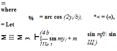
Подпись:ci (C =y,

(m, і = 1, 2, • • •, я) (12)

then Eq. 11 may be written as

A’ E = a (13)

where A’, a’ denotes the transpose* of A and a, respectively. Hence,

A’ = a’ E-1

(14)

Let

© = {©mi} = 4b {sin my,}

(15)

Then, according to Eqs. 10, 14, we obtain

CC;’ = A© = ctE-1©

(16)

Hence,

cC, = ©'(Z-^’a

(17)

or

a = E'(0-1),cC[

(18)

Similar matrix representation for other methods of solving the lifting­line equation can be made.4,38 In all cases, we may write the result as

Подпись: (19)cC; = yga

where Л is a square matrix, to be identified as ac according to Eq. 9, or as ©'(Z-1)’ according to Eq. 17.

Подпись: a
Подпись: <r) Подпись: ld£i a0 dp Подпись: (20)

The deflection of the control surface may be regarded as an initial twist and can be included in a(r). The equivalent angle of attack corresponding to a control-surface deflection p is

where a0 and dCjdp are the two-dimensional values of the airfoil section. Of course, Cm must be properly related to p.

Equation 4 can be represented in matrix form as follows:

Подпись: Sw 8s Fi cosЛ cSC; + (Hj cos2A – ^ sin A cosA j c2S(eC, + CMj

(21)

A similar expression for 0 is obtained by replacing Hj by F2, H2, respectively. In Eq. 21. e, sin A, cos A are diagonal matrices whose elements are, respectively, values of e, sin Л, and cos Л evaluated at the points (лі, л2, • • •, sn). S is a diagonal matrix of “weights” defined by Eq. 14 of § 3.7.

* Interchange of rows and columns.

Combining Eq. 21 with Eqs. 3, 5, and 19, we obtain сСг = Jfa. = A[a(r) + ot(e)]

Подпись: a(r) + cosAO — sin AПодпись: (22)3w

3s

= AWT) + ?E cC, + gGc2Cm]

Подпись:Подпись:/ 8F, 3F, 1

— I cos A ——– sin A —— I sin A cos A ceS (23)

Эо 8 a / J

/ 8F, 8F,

G = (cosAH2—sinAH1)cos2A— I cos Asin ЛI sinAcosA S

For conventional airfoils Cm depends on /3, but is independent of a. Equation 22 can be written as

(I – q№)cCt = A[*{r) + ?Gc2CJ (24)

Hence,

сСг = (I – qAE)-1 AWr) + ?Gc2CJ (25)

The lift per unit span qcCt can therefore be obtained by matrix operations. For a given value of q, the inverse (I — qAJ&T1 can be calculated by Crout’s method.

When the matrix I — qA& is singular, i. e., when the determinant |I — qAM vanishes, the inverse (I — qAEY1 does not exist. The lift distribution corresponding to a change in angle of attack <x(r) becomes indeterminate (tending to infinity). The value of q that satisfies the condition

|I – qAE| = 0 (26)

is the dynamic pressure at divergence.

An eigenvector (i. e., a column matrix) u satisfying the equation

(A$——- —-11 u = 0 (27)

‘ 7tiiv ‘

can be determined by a method of iteration as follows. Starting with an arbitrary nonvanishing vector % we compute successively the following sequence:

“o

Ui = Л&Щ

u2 = = (j№)2u0 (28) u„ = A^in-1 = (№)’

It can be shown that, if qilv is the smallest, (in absolute value), simple, real eigenvalue,*

lim —-^aiv (29)

n-*co U-п

and, aside from a numerical factor,

lim u„ – s – u (30)

П—У 00

where u is an eigenvector satisfying Eq. 27 and the ratio un_-Jun means the ratio of the corresponding elements in the column matrices and u„. Equation 29 is useful for calculating the divergence speed.

Let us choose a particular vector u0:

Uo = AWr) + *Gc*CJ (31)

Equation 25 can be written as

cC; = (I – qMY

00

= «о + ^iq£Ef% (32)

= 110 + ^% + q% u2 + ■■■ + qkuk + – ■ ■

Let m be so large that um approximates the eigenvector u with negligible error. Then, for k^m,

= G€e)4 = (-M Щ (33)

Vfdiv’

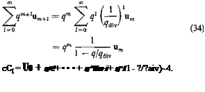
The remainder after m terms in the series on the right-hand side of Eq. 32 can be summed as follows:

Подпись: cC( = Uo + q»! + • • • + q^Um-i + qm( 1 - ?/?aiv)~4. (35)

Therefore,

The series expansion can be justified* for q < |^dW|. The form of the

* See Ref. 3.20, §§4.14-4.17, p. 134. The existence of a real eigenvalue cannot be assured when the matrix AE is unsymmetric. For Eq. (35), see Ref. 3.20, §3.9, p. 81.

solution 35 was first given by Pines.4,30 In practical applications, it is often sufficient to take m = 2 or 3.

For certain sweptback wings, <jrdiv is negative. Physically the wing will not diverge. Yet the convergence of the series in Eq. 35 fails when q > |?divl – A method of extending the radius of convergence is discussed by Gaugh and Slap.4-29

Aileron Reversal. The rolling moment about the airplane centerline is

THE EFFECT OF ELASTIC DEFORMATION ON THE LIFT DISTRIBUTION(36)

where {;у„}’ is a row matrix with yn as elements.

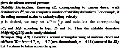
If we take a(r) and CM in Eq. 25 as those corresponding to the aileron deflection /5, the solution q of the equation

Подпись:

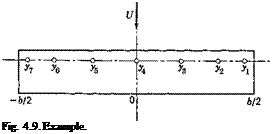
Подпись: gives the aileron reversal pressure. Stability Derivatives. Knowing сСг corresponding to various down- wash distributions a(r), we can compute a number of stability derivatives. For example, if the rolling moment Мф due to a steady rolling velocity cCt and Мф according to Eqs. 25 and 36. Then the stability derivative дМф/d(pbj2U) can be easily obtained. Example (Fig. 4.9). Consider a normal rectangular wing of uniform chord and stiffness. Ж = b/c = 5.7, a0 — 5.7 (two-dimensional), a = 4.16 (corrected for JR). Let 7 stations be taken across the span:

Мф.= 0 Ф Ф 0)

Using Prandtl’s lifting-line theory, find the symmetrical lift distribution corresponding to a change of angle of attack at the wing root.

Подпись: H2(s, a) = THE EFFECT OF ELASTIC DEFORMATION ON THE LIFT DISTRIBUTION Подпись: (39)

Since Л = 0, only F2(s, a) and H2(s, a) are needed. For a uniform beam having a straight elastic axis, F2(s, a) = 0, and

Подпись: Fig. 4.9. Example.

In Eq. 39, s, a are measured from the wing root. These expressions are valid for positive s, a. For the other half of the wing, the sign on the

right-hand side of Eq. 39 should be changed so that H%(s, a) remain positive.

* a~* (у,) (ys)

(yi) 0.92388 0.70711 (у г) 0.70711 0.70711 (У.) 0.38268 0.38268 (у.) 0 0

THE EFFECT OF ELASTIC DEFORMATION ON THE LIFT DISTRIBUTION Подпись: (Уз) (У») 0.38268 0' 0.38268 0 0.38268 0 0 0 Подпись: (40)

In expressing H2(s, a) in the form of a matrix, let the points of loading be уъ у2, ‘ ‘ Уп specified by Eq. 38. Then

Подпись:Подпись: (41)The auxiliary matrices {cos2 Л) and {ce} are diagonal matrices, this example Л and ce are constants, we have

{cos2 Л} = cos2 ЛI = I, for Л = 0

{ce} = cel

The matrix /I is to be found by the Glauert’s method. The lift distribution
being symmetrical, only terms of odd indices in Eq. 10 differ from zero. Hence, let m = 1, 3, 5, 7:

4 b V’

Подпись: c АГ = 1,3, 5, 7 Ci = — / An sin тв (42)

The matrix defined by Eq. 12 depends on the quantity 4b/a0c which is 4 in this example:

Подпись:4 b.

Its inverse is*

THE EFFECT OF ELASTIC DEFORMATION ON THE LIFT DISTRIBUTION THE EFFECT OF ELASTIC DEFORMATION ON THE LIFT DISTRIBUTION

Then 2 can be easily calculated:

0. Подпись: AПодпись: (48)29503 0.12520 0.04353 0.02010

0. 06777 0.46898 0.14736 0.03394 |

0. 01799 0.11275 0.55790 0.11970

0. 01536 0.04796 0.22120 0.54776

* Though not tabulated here, 5 significant figures were obtained for S_1 and were used for subsequent calculations.

The matrix S is the weighting factor for the integration. Using Multhopp’s formula, (§ 3.7, Eq. 16), we have


‘ sin 6t

0

0

0

0

sin 02

0

0

0

0

sin 63

0

V. 0

0

0

C/a) sin

0.38268

0

0

0

0

0.70711

0

0

0

0

0.92388

0

0

0

0

0.5


(49)


THE EFFECT OF ELASTIC DEFORMATION ON THE LIFT DISTRIBUTION

Hence,


0.14456 0.022189 0.16396 0

7rcebs I 0.17244 0.30825 0.24187 0

32 GJ 1 0.11857 0.21634 0.24347 0

0.05080 0.09152 0.10059 0


M"


(52)


THE EFFECT OF ELASTIC DEFORMATION ON THE LIFT DISTRIBUTION

THE EFFECT OF ELASTIC DEFORMATION ON THE LIFT DISTRIBUTION

THE EFFECT OF ELASTIC DEFORMATION ON THE LIFT DISTRIBUTION

where

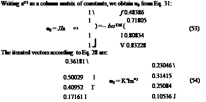
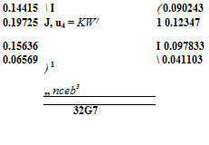
Подпись: 0.14415  I ( 0.090243 0.19725 J, u4 = KWr) 1 0.12347 0.15636 I 0.097833 0.06569 ) 1 „ nceb3  0.041103 32G7 Подпись: u, = Ksba.(r)

THE EFFECT OF ELASTIC DEFORMATION ON THE LIFT DISTRIBUTION Подпись: Щ ; «d
THE EFFECT OF ELASTIC DEFORMATION ON THE LIFT DISTRIBUTION

The ratio of the corresponding elements of the successive iterated vectors is:

Clearly the convergence of the ratios to qdiv is approximately established by n = 3, and we may take

32 GJ

qdiv= 1.598 —дг (56)

According to Eq. 35, the lift distribution across the span is given by

сСг = u0 + + q*u2 + qs "3 (57)

Подпись: (r) THE EFFECT OF ELASTIC DEFORMATION ON THE LIFT DISTRIBUTION

Using Eq. 56, and defining iq, fl2, etc. to be the column matrices given by Eq. 54 but with the factors Knba.{r) removed, we can write Eq. 57 as

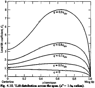
where a0 is the two-dimensional lift-curve slope which is equal to Ж = bjc in this particular example. For a few special values of the ratio qjq^, the results shown on the next page are obtained. This is plotted in Fig.

4.10 for a change of angle of attack a<r) = 1 /a0 radian.

If the wing were perfectly rigid, then H2 = E == 0, and the lift distribution is simply given by u0> This is also plotted in Fig. 4.10 as the q = 0 line.

?/?div

0

0.5

0.7

0.8

0.9

C; matrix for

0.4839

1.0671

1.8495

2.8289

5.7691

0.7180

1.5196

2.7011

3.9316

7.9551

a0 a(r) = 1

0.8083

1.4552

2.3098

3.3752

6.5675

0.8323

1.1037

1.4626

1.9101

3.2512

Подпись: Fig. 4.10. ' Lift distribution across the span. (aw = 1 /я0 radian).

THE LIFT DISTRIBUTION ON A RIGID WING

In previous sections the spanwise-lift distribution over a finite airfoil is generally assumed to be given by the strip theory, according to which the local lift coefficient is proportional to the local angle of attack a. This approximation is a crude one, but is sufficient for certain purpose.

* Except possibly when h2(y) is orthogonal to the eigenfunction.

To account for “induction” properly, more refined theory should be used.

For a wing with very small angle of sweep, Prandtl’s lifting-line theory may be used. In this case the local lift coefficient Cfy) is given by the following integral equation:*

THE LIFT DISTRIBUTION ON A RIGID WING(1)

Подпись: * The integral in Eq. 1 is divergent in the ordinary sense, but can be defined by its Cauchy principal value. The Cauchy principal value of an integral is defined as follows: where is a singular point of f(x) in (a, b). t For Glauert’s method, see his book, Aerofoil and Airscrew Theory (1926), and R. F. Anderson: NACA Rept. 572 (1940). For Lotz’s method, see her paper in Z. Flugtech. u. Motor lyft. 22, 189-195 (1931), and H. A. Pearson, NACA Rept. 585 (1937). For Hildebrand’s'method (a least-squares procedure), see NACA Tech. Note 925 (1944). For Multhopp’s method, see Luftfahrt-Forsch. 15, 153-169 (1938). For Sears’s method, see Quart. Applied Math. 6, 239-255 (1948). J See Eqs. 36, 37 of Ref. 4.58. See also Ref. 4.57.

where у is the spanwise location, afy) is the two-dimensional lift-curve slope of the airfoil section at y, and <x(y) is the angle-of-attack distribution required to produce the lift-coefficient distribution Cfy). <x(y) is the geometrical angle of attack between the zero-lift line of the section and the flight direction. Methods of solving Eq. 1 have been proposed by Glauert, Lotz, Hildebrand, Multhopp, and Sears. f For swept wings and wings of small aspect ratio (say less than 5) Prandtl’s lifting-line theory does not apply. To obtain accurate results it is necessary to use a lifting-surface theory in which an airfoil is replaced by a continuous distribution of vorticity over a surface. Unfortunately the calculation becomes involved and only a small number of solutions exist at present (see refs. 4.39, 40, 41, 44, 45, 48, 49, 50, 56). However, a modification of the Prandtl theory, known as Weissinger’s method, gives a good approximation for swept wings. In Weissinger’s method the bound vorticity of the wing is concentrated into the x/4-chord line, and the downwash is calculated at the 3/4-chord line. The condition that the down wash angle be equal to the slope of the wing with respect in the direction of flow is then applied at the 3/4-chord line. This results in an integral equation governing the lift distribution similar to Eq. 1, but with a continuous function added to the original kernel.^ Practical methods of solution are given by Mutterperl4-52 and Weissinger.4 58

A short empirical approximate method for estimating the spanwise lift distribution is given by Schrenk4-54 for a normal (unswept) wing, and is extended to sweptback wings by Pope and Haney.4 53

So far the compressibility effect is neglected. The compressibility of the fluid is expressed in terms of the Mach number M*

When the airfoil speed is subsonic (M < 1), the change in the lift-curve slope is given approximately by Glauert’s formula4 46:

ag — — ag (2-dimensional) (2)

VI — M2

THE LIFT DISTRIBUTION ON A RIGID WING THE LIFT DISTRIBUTION ON A RIGID WING Подпись: unswept, subsonic, 144 symmetric loading, I moderate Ж / (3)

where a0 is the value of ЭСг/За for a compressible fluid, and ctg that for an incompressible fluid (M = 0), both in a two-dimensional flow. f The effect of finite span is then approximately given by the following formulas:

Подпись: a Подпись: a o(l + T) 77Ж Подпись: unswept, subsonic, sym- J metric loading, small Ж / Подпись: (4)
THE LIFT DISTRIBUTION ON A RIGID WING

where a’ is the lift-curve slope of a wing of finite aspect ratio in a com­pressible flow, and г is the same Glauert’s correction factor for nonelliptic planform (Fig. 1.13, p. 35). For very small Ж, we have

Equation 4 yields the correct limiting value for wings of very low aspect ratio.§

77 /unswept, incompressible

Лa ~ 2 symmetric loading, Ж 0/ ^

(*7o)swept ‘ «0 cos A

Подпись: incompressible, infinite span, swept wing Подпись: (6)

The effect of sweep angle is incorporated in the following formulas:

_____ (Vo)*wept____________ ,

(VoXweptV, pXweptO T) (

ttJR / ‘ ттЖ

THE LIFT DISTRIBUTION ON A RIGID WING THE LIFT DISTRIBUTION ON A RIGID WING THE LIFT DISTRIBUTION ON A RIGID WING

where a0 is the lift-curve slope of the airfoil section normal to the leading edge.

where JR is the aspect ratio b2jS (b — the wing-span from tip to tip, S = the wing area).*

If the wing is tapered, the sweep angle A should be measured along the V4-chord line. The values of т are given in Fig. 1.13 (p. 35).

For antisymmetric spanwise lift distribution, the effective aspect ratio is approximately one-half that of the entire wing. Therefore, an approxima­tion is obtained by replacing JR in Eq. 8 by

JRe — JR/2 (antisymmetric loading) (9)

Eqs. 3, 4, 8, and 9 are useful in aeroelasticity. By means of these corrections, the errors of the strip theory are greatly reduced.

Because of the difference in the effective aspect ratio for the symmetric and antisymmetric spanwise load distributions, the corrected values of a should be distinguished for the two cases. Let the spanwise angle of attack a(y) be separated into two parts, one symmetrical in у and another antisymmetrical in y,

<У) = asym(2/) + “antisym ІУ) (Ю)

then we may write

CM = OV-ayrniy) + ««antisym ІУ) (1 0

For a, Eq. 4 or 8 can be used. For 3, the aspect ratio in Eqs. 4 and 8 should be replaced by JRe = JR/2.

The equations quoted above are not valid when the wing approaches stalling, either because of too high an angle of attack or because of too high a speed of flight. The former is stalling in the conventional sense; the latter is called shock stall, and is due to the formation of shock waves over the wing. Both involve a loss of lift and an increase of drag. Shock stall occurs when the free-stream Mach number exceeds the Mach number

* T. A. Toll and M. J. Queijo, NACA Tech. Note 1581 (1948); F. W. Diederich, NACA Tech. Note 2335 (1951).

of “divergence” MCI which is defined as the point of inflection of the curve of lift coefficient plotted against the Mach number (see Fig. 4.6 and Fig. 9.2).

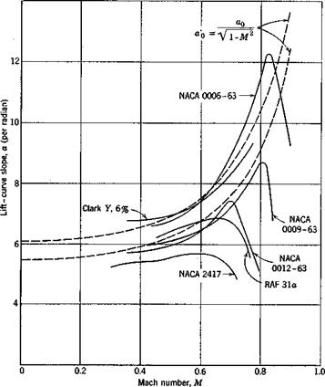
In Fig. 4.6 the lift-curve slope is plotted against M for several airfoils. It is seen that Glauert’s formula (Eq. 2) gives a fair approximation for

THE LIFT DISTRIBUTION ON A RIGID WING

Fig. 4.6. The variation of lift-curve slope with Mach number.

lower Mach numbers, and that, when MCI is exceeded, the lift-curve slope decreases sharply.4-37

When the free-stream Mach number is sufficiently large, both subsonic and supersonic regimes are present in the field of flow. This is the transonic regime in which both the force and moment coefficients and the angle of zero lift change substantially. The variations are too complicated to be reviewed here.

When the free-stream Mach number is larger than one, the flow is supersonic. When M is sufficiently high, the linearized theory again gives a good approximation.* Let a pressure coefficient be defined by the equation

Подпись:C – p ~Po

9 W/2

Подпись: (Qu Подпись: dY Подпись: (13)

where p is the local pressure, and p0, p0, U refer to quantities at a large distance from the airfoil. Then, according to the linearized theory, the pressure coefficient at any point on a two-dimensional airfoil is propor­tional to the local slope of the surface. If the surface of a two-dimensional airfoil is represented by the function у = Y(x), thenf

where the subscript “upper” indicates the upper surface of the airfoil. The corresponding formula for the lower surface is obtained by replacing the right-hand side with a negative sign. The total lift coefficient is given ЬУ

4 t

CL =-—==- (two-dimensional, supersonic) (14)

VM:2 — 1 c

where c is the chord length, т is the normal distance between the trailing edge and the line parallel to the flow direction passing through the leading edge, r/c can be identified as the angle of attack. Hence,

a = = – г:" , = (supersonic) (15)

0 Эос /0 VM2 – 1

For a flat-plate airfoil, the slope dYjdx is constant; Eq. 13 implies that the center of pressure is at the mid-chord point.

For wings of finite span a supersonic flow differs from the two-dimen­sional one only in the tip region. For wings of small aspect ratio, the lifting-surface theory must be used. Many cases of lifting-surface theory have been worked out for a linearized supersonic flow.4,47

For a swept wing of large aspect ratio with a measured in the free-stream direction, we obtain, analogous to 7,

THE LIFT DISTRIBUTION ON A RIGID WINGЭCL _ 4 cos Л /supersonic leading edge,

до: */M2 cos2 Л — 1 cos Л > 1

* See for example, R. E. Bolz and J. D. Nicolaides, J. Aeronaut. Sci. 17, 609-621 (1950).

t See Liepmann and Puckett, Ref. 1.46, p. 145.

AILERON REVERSAL—GENERAL CASE

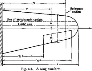
Let us consider a wing without sweep and having a straight elastic axis when the aileron is locked, and again make the strip assumption on aerodynamic forces. The wing is assumed to be built in at the fuselage which is immobile in roll. Let the aileron deflection angle be denoted by P(y) and the corresponding wing twisting angle about the elastic axis by

9(y).* These functions are linearly related through elastic equilibrium. We shall write

%) = 00f(y) (0 < у < s)

0ІУ) = Pog(y)>

where g(y) in (y-Ls < у ss: y2s) (1)

g(y) = 0 elsewhere

AILERON REVERSAL—GENERAL CASE

0o and are constants, and the functions f(y) and g(y) define the deforma­tion pattern of the wing and the aileron, respectively. The ranges of definition off(y) and g(y) are indicated in the parentheses, where yxs and

y2s are locations of the inboard and outboard ends of the aileron, respec­tively (see Fig. 4.5).

In accordance with the strip assumption, the lift acting on a chordwise element of span dy is given byf

Подпись:Подпись: cdyПодпись: (2)L'(y) dy — q

* 0(2/) and P(y) are measured from the steady-flight values. Initially, at the flight speed U, the airplane wing may have some twist, and the aileron may have some deflec­tion for trimming, but the whole airplane is in a steady-state equilibrium. These initial values do not affect our problem.

t The lift-curve slope a should be corrected for finite-aspect ratio (cf. § 1.5 and § 4.3) parent.

Подпись: Aft AILERON REVERSAL—GENERAL CASE Подпись: су dy Подпись: (3)

The total induced rolling moment about the airplane centerline is therefore

Подпись: i.e., Подпись: (4)
AILERON REVERSAL—GENERAL CASE

At the critical aileron-reversal speed, a deflection of the aileron produces no resultant rolling moment, so that

The relation between^?/) and g(y) and the ratio d6Jd80 must be found from the condition of elastic equilibrium of the wing. Again, by the strip assumption, the contribution to the aerodynamic twisting moment about the elastic axis from an element dy is

ЭС

M’a dy = L'(y) e(y) c(y) dy + q c2(y)8(y) dy (5)

dp

Let G(x, y) be the influence function of wing rotation at x due to a unit couple at y; then, the wing being in static equilibrium, the total angle of rotation б at a; is

Подпись: (6)в(x) = £ G(x, y) M’a(y) dy

According to the strip-assumption equations 2 and 5, the above integral becomes

Подпись:в(х) = G(x, y) ja e(y) 6{y) + or, substituting Eq. 1,

% f{x) = G(x, y) ja e(y) 60 fly) + e(y) + ^j 80 g(y) j cy) dy

(8)

A second equation governing the angle of aileron deflection P(y) across the aileron span can be derived in a similar manner. Generally, however, the aileron may be regarded as perfectly rigid. Then P(y) is constant, and we may assume g(y) = 1. This approximation is sufficiently accurate
for most ailerons. For more flexible ailerons a semirigid mode of the aileron deflection may be assumed. Thus g(y) may be regarded as a known function of y.

The function g(y) being known, the function 60f(x)jfj0 will be given by Eq. 8. The solution depends on q. By substituting g(y) and 60j'(y)lfi0 = (d0o/d(3o) f(y) into Eq. 4, the critical value of q can be computed.

Semirigid Solution. As a first approximation let us again apply the semirigid theory. We assume that the modes of the aileron deflection and the wing twisting are known; i. e., reasonable forms of the functions f(y) and g(y) are assumed. A process of reasoning entirely analogous to that in § 3.3 may be used to derive the solution corresponding to the assumed semirigid modes. We choose first a reference section at у — r, transfer all aerodynamic moments about the elastic axis to the reference section, and consider the rotation of the reference section to obtain the final result. For a greater variety in the ways of reasoning, however, we may proceed slightly differently as follows: Since the wing twisting mode f(y) is assumed not to vary with the load distribution, it also represents the deformation pattern of the wing due to a couple acting at the reference section. Let an angle of rotation at the reference section 6r – ff0/(r) correspond to a couple M acting at the reference section, so that

M = KOJ(r) (9)

К being the torsional stiffness at the reference section as defined by Eq. 5 of § 3.3. Then a unit moment at the reference section will produce a rotation

ОоЛу) = 1Ш

M К f(r)

across the span. This is, by Maxwell’s reciprocal theorem, precisely the influence function G{r, y). Hence, the semirigid assumption implies an approximation

Подпись: (И)r( , і f(y)

а^~кт

«да-*»*

л* г

= A)?’"2 :

Jo L

Подпись: 60K-qc AILERON REVERSAL—GENERAL CASE AILERON REVERSAL—GENERAL CASE

Substituting Eq. 11 into Eq. 8, putting x = r, dividing through by /(r) (Ф 0), rearranging terms, and introducing the mean aerodynamic chord c as a characteristic length, we obtain

Подпись: where AILERON REVERSAL—GENERAL CASE AILERON REVERSAL—GENERAL CASE

Substituting this relation into the critical reversal condition (Eq. 4), we obtain the critical reversal speed

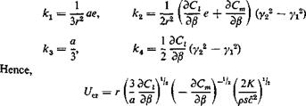
The U„ so obtained is influenced by the arbitrariness in the choice of the reference section. To remove such arbitrariness, the method of generalized coordinates (see § 3.4) may be used. The details are left to the reader.

AILERON REVERSAL—GENERAL CASE

Example. Consider a rectangular wing with a rectangular aileron, and assume

AILERON REVERSAL—GENERAL CASE

g(y) — 1 when < у < y2s, = 0 elsewhere Let the reference section be taken at у = rs; then

This should be compared with the two-dimensional result (Eq. 9 of § 4.1). In this particular case, the critical reversal speed is independent of the aileron span.

The above example shows that the terms involving the eccentricity e do not appear in the critical-reversal-speed expression for a uniform rectangular wing with a rectangular aileron. This suggests that in the general case the contribution of the terms involving e is small. Pugsley proposes to neglect these terms entirely.412’49 Equation 15 is then simplified into

Подпись:Подпись: U„(17)

where

Подпись: (18)і [v*zcn№g(y)c-

S Jns Э/8 /2(r) c2

In an incompressi ble fluid, the error induced by neglecting e is unlikely to exceed 4 per cent in any conventional tapered wing.4-9 Equations 15 and 17 show that the aileron-reversal speed can be raised by increasing the wing torsional stiffness.

AILERON REVERSAL—GENERAL CASE Подпись: c2(y)g(y)dy Подпись: (19)

Solution by the Method of Successive Approximations. If the aileron is sufficiently stiff so that g(y) — 1, or if g(y) can be assumed as a known function of y, we may put

Equations 4 and 8 then become, respectively,

Подпись:a f f(y) c(y) у dy = – hM Jo 110

AILERON REVERSAL—GENERAL CASE Подпись: (22) (23)

f(pc) = qajo G(x, y) e(y) c2(y)f(y) dy + q h2(x) ^

K(x, y) is a continuous function of x, y. Equation 22 is a homogeneous Fredholm’s integral equation of the second kind, of the same form as the divergence equation 3 of § 3.2. The method of successive approximations

AILERON REVERSAL—GENERAL CASE

described in § 3.5 can be applied here. The smallest positive eigenvalue b is the physically significant reversal dynamic pressure.

Equation 21, regarding h2(x) as a known function, is a nonhomogeneous Fredholm integral equation of the second kind. If we compare Eq. 21 with Eq. 3 of § 3.2 it is seen that they are identical but for the last term.

tion for which nontrivial solution f(y) exists only for the eigenvalues qdiv. It is well known that a nonhomogeneous equation such as 21 has no solution when q is equal to an eigenvalue,* whereas a unique solution f(x) exists if q is not an eigenvalue. Physically, if q — qi[v there will be no question of aileron reversal since control is impossible. If q Ф qdiv, then, for each specified deflection of the aileron, there corresponds a unique deflection curve of the wing.

The method of successive approximation can be applied to Eq. 21 as follows. Let

ф(рс) =- ~q h2(x)

H(x, y) =- a G (x, y)e(y)c2(y)

Подпись: (24)
AILERON REVERSAL—GENERAL CASE

We compute the following sequence of functions: f0(x) = ф(х)

The sequence converges to a unique solution f(x) of Eq. 21 for values of q within a finite radius of convergence r < |<7div|.

LOSS AND REVERSAL OF AILERON CONTROL-. TWO-DIMENSIONAL CASE

Ailerons control the rolling motion of an airplane. When an aileron is displaced downward, the lift over the wing increases, thus producing a rolling moment. But the aileron deflection also creates a nose-down aerodynamic pitching moment which twists the wing in a direction tending to reduce the lift and hence reducing the rolling moment. As the elastic stiffness of the wing is independent of the flight speed, whereas the aerodynamic force varies with U2, there exists a critical speed at which the aileron becomes completely ineffective. This critical speed is called the critical aileron-reversal speed. When the airspeed is higher than the critical reversal speed, the aileron control is reversed; i. e., a downward movement of the aileron on the starboard wing produces a rolling moment which moves the starboard wing tip downward. The closer the speed is to the critical speed, the less effective is the aileron control. The effectiveness of the aileron control may be expressed in terms of the rolling power of

LOSS AND REVERSAL OF AILERON CONTROL-. TWO-DIMENSIONAL CASE
the wing, which may be defined as the ratio of the steady rolling velocity of an airplane, due to a unit deflection of the aileron, to that of an other­wise identical airplane in the same flight condition but with an infinitely rigid wing. However, in order to simplify the problem and to obtain a convenient index for the aeroelastic characteristics of the wing itself, we shall consider the aileron control problem in a strictly static sense. We define the elastic efficiency of the aileron, or simply the aileron efficiency, as the ratio of the rolling moment produced by an aileron deflection to that produced by the same deflection on a hypothetical rigid wing of the same planform, while the wing root is rigidly held against roll. The situation may be conceived as existing in a wind-tunnel testing. The airplane

fuselage is fixed in the tunnel, while the aileron is deflected and the rolling moment measured.

Since the net rolling moment vanishes at the reversal speed, both the “rolling power” and the “elastic efficiency” become zero at the critical condition.

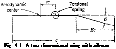
Let a be the geometrical angle of attack (measured from the zero-lift line) at a section of the main airfoil, and (j the angle of deflection of the aileron (positive downward) with respect to the main airfoil at that section (see Fig. 4.1).

LOSS AND REVERSAL OF AILERON CONTROL-. TWO-DIMENSIONAL CASE

The lift coefficient and the coefficient of moment about the aerodynamic center can be written in the form

„ЗС,

c, = «« + ^

(1)

Cm = /3 -^r + OnO

(2)

1 ЭС /ЭС ~~i

Подпись: where E is the ratio of the flap chord to the total chord (Fig. 4.1). For a finite wing with partial-span aileron, corrections are needed; but the

Подпись: Э/3

Подпись: - - (1 - E)VE( 1 - E)
Подпись: (p in radians) (4)

effect of finite aspect ratio on the combination – —^ I, which

a op Op /

LOSS AND REVERSAL OF AILERON CONTROL-. TWO-DIMENSIONAL CASE

appears in the reversal problem, is small, provided that the lift-curve slope

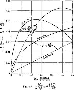
a is properly corrected for finite aspect ratio. Comparison with experi­mental results418 shows that the mean values of both (1/а)(ЭСг/Э/3) and at “incompressible” speeds lie at about 80 per cent of the theo­retical values. The experimental values are, however, scattered and are influenced by the design details of the flap, such as its nose shape, nose gap, and aerodynamic balance.

The theoretical values of the ratios (1 /aXBCJdfi) and (1/а)(ЭСт/Э/1) are summarized in Fig. 4.2 for both the subsonic and the supersonic cases.

Let us consider a two-dimensional wing with chord length c and aileron chord length Ec, constrained by a spring to rotate about an axis at

Подпись: U = qc LOSS AND REVERSAL OF AILERON CONTROL-. TWO-DIMENSIONAL CASE Подпись: (5)

distance ec aft of the aerodynamic center. In this case we shall say that aileron reversal occurs when the change of lift due to an aileron displace­ment vanishes. The lift per unit length of this airfoil is, according to Eq. 1,

Подпись: i.e., LOSS AND REVERSAL OF AILERON CONTROL-. TWO-DIMENSIONAL CASE Подпись: (6)

Hence, at the critical reversal condition,

Now the angle of twist a of the airfoil is related to the angle of deflection of the aileron through the elastic constraint. The aerodynamic pitching moment per unit length of span about the axis of rotation is, according to Eq. 2,

M’ = q<*(eC, + P^ + cJ)

This pitching moment is balanced by the elastic restoring moment. Let К be the stiffness of the torsional restraint per unit span of the airfoil. The elastic moment induced by a rotation of the airfoil through an angle a is а К. Hence,

«К = qc2 [eCi + £“■+ Cm0j = qc2 {eav. + e$ + Q. o)

(7)

Differentiating with respect to /?, we obtain (Cm0 being a constant)

Эа / Эа ЭС, ЭСт

кЩ-**(аЩ + ег?+-гё

=)’ (7 a)

LOSS AND REVERSAL OF AILERON CONTROL-. TWO-DIMENSIONAL CASE

Substituting Эа/Э/? from Eq. 6, we obtain the critical dynamic pressure

LOSS AND REVERSAL OF AILERON CONTROL-. TWO-DIMENSIONAL CASE

Hence, the reversal speed is given by

which shows that the critical reversal speed increases with increasing stiffness К of the airfoil. Note that the quantity e is absent from this

formula; i. e., the position of the torsional axis does not affect the reversal speed. The reason is that the net change of lift due to aileron displace­ment is zero at the reversal speed.

Подпись: da LOSS AND REVERSAL OF AILERON CONTROL-. TWO-DIMENSIONAL CASE

In order to compare the loss of controlling power of an aileron due to the elastic deformation, let us define, in the two-dimensional case, the elastic efficiency of the aileron as the ratio of the lift force produced by a unit deflection of the aileron on an elastic wing to that produced by the same aileron deflection on a fictitious rigid wing of the same chord length. Now, from Eq. la, we obtain

Подпись: dL dp Подпись: J ЭС, эсж aqcew+w) К — qc2ea Подпись: ЭQ 3/Ї.

Hence, the rate of change of lift due to an aileron deflection is, according to Eq. 5,

On the other hand, if the wing is perfectly rigid so that К -> со, then dajdP = 0, and the rate of change of lift would be

dL’ о Э C,

dp qC dp

The elastic efficiency of the aileron is, therefore,

dL’jdp

dL’jdp

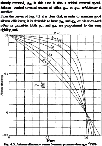
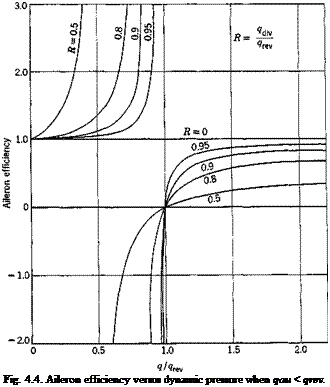
Introducing the critical-divergence dynamic pressure qdly given by Eq. 6 of § 3.1, and the critical aileron-reversal dynamic pressure qiev given by Eq. 8, we can write the above ratio as

Elastic efficiency = – J—— — (10)

1 – ?/?div

When qiev < qdiv, the aileron efficiency decreases to zero when q -> qKV, as shown in Fig. 4.3, where the aileron efficiency is plotted against q/qKV, with the ratio R = qdiv/qTeY as a parameter. On the other hand, if qiev > qilv, dL’/dp -> со when q -> qdiv, as shown in Fig. 4.4; but, for qdiv < q < qlev, the aileron efficiency is negative, and the control is

Подпись: already reversed, qdly in this case is also a critical reversal speed. Aileron- control reversal occurs at either qlev or qdlv, whichever is smaller. From the curves of Fig. 4.3 it is clear that, in order to maintain good aileron efficiency, it is desirable to have q№y and qdiv as close to each other as possible. Both qKV and qdlY are proportional to the wing rigidity, and ll^rev Fig. 4.3. Aileron efficiency versus dynamic pressure when qdw ^rev-

can be raised by increasing the rigidity. But qdlv ~ l/e, and qKy ~

Подпись: ±1 ВВ/ p Hence, the requirement qKy = qd[v implies an optimum

relation between the aileron dimensions and the wing aerodynamic center – elastic-axis eccentricity. In the two-dimensional incompressible case, an optimum aileron chord ratio as a function of the eccentricity e is given by the condition

LOSS AND REVERSAL OF AILERON CONTROL-. TWO-DIMENSIONAL CASEПодпись: (П)ffrev

9div

and Glauert’s formulas (Eqs. 3 and 4); i. e.,

Подпись: (12)(1 – E)VE( 1 – E)
arc cos (1 – 2E) + 2/£(l – E)

Подпись: Fig. 4.4. Aileron efficiency versus dynamic pressure when qau < qrev.

For example, if the elastic axis is located at 40 per cent chord behind the leading edge, the optimum aileron chord ratio is 31 per cent.

GENERAL

Generalization of the analysis of the previous chapter to include the more accurate aerodynamic theories will be considered in this chapter together with other steady-state problems. The problem of loss of aileron efficiency and reversal of control will be discussed in §§ 4.1 and 4.2. Although the nature of the reversal problem is entirely different from that of the divergence problem, the methods of solution are analogous. Hence, we shall emphasize only the physical aspects of the problem without going into the details of calculation.

In § 4.3, the aerodynamic-lift distribution over a rigid wing is reviewed. In § 4.4, the effect of elastic deformation on the lift distribution is treated. These are followed by discussions of swept wings in § 4.5, tail efficiency in § 4.6, static longitudinal stability of an airplane in § 4.7, and twisting of propeller blades in § 4.8. It is possible to formulate many other steady-state problems, but the typical methods of analysis are well illus­trated by the examples treated here.

NUMERICAL APPROXIMATIONS — REDUCTION OF INTEGRAL EQUATIONS INTO MATRIX EQUATIONS

In practical numerical calculations, the integral equations of the pre­ceding sections can be replaced by matrix equations. As a physical * Sometimes also called latent roots, or eigenvalues.

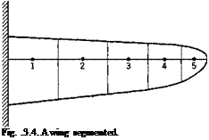
example, consider the divergence of the cantilever wing shown in Fig. 3.4. In analyzing the wing deformation approximately, it is natural to divide the wing into a number of segments. The loading on each segment may be assumed as concentrated at a reference point in the segment. The average angle of rotation in each segment is represented by that measured at the reference point. Let ві be the angle of rotation of the ith segment, and Mt the aerodynamic moment in the same. Let the influence coefficient

Подпись: Fig. .3.4. A wing segmented. у

for rotation at the rth segment due to a unit moment at the y’th segment be denoted by ctj. Then the total rotation at і is obtained by summing over the effects of all the moments:

Подпись: П j=i (1)

NUMERICAL APPROXIMATIONS — REDUCTION OF INTEGRAL EQUATIONS INTO MATRIX EQUATIONS Подпись: (2) Подпись: e = R}
NUMERICAL APPROXIMATIONS — REDUCTION OF INTEGRAL EQUATIONS INTO MATRIX EQUATIONS
Подпись: M = {Mi) =
NUMERICAL APPROXIMATIONS — REDUCTION OF INTEGRAL EQUATIONS INTO MATRIX EQUATIONS

where n is the total number of segments in which the wing is divided. It is convenient to write в{ and Mt as matrices в and M:

Then Eq. 1 can be written simply as

9 = c • M or {0J = {cw}{M,} (4)

M is a linear function of 6 and is proportional to the dynamic pressure q. Hence, we may write, in general,

M = #A • 9 (5)

Подпись: or

{M^ = q{AM}

NUMERICAL APPROXIMATIONS — REDUCTION OF INTEGRAL EQUATIONS INTO MATRIX EQUATIONS

where {Ah} is a square matrix. The form of the matrix A depends on the aerodynamic theory used (cf. § 4.5). In particular, if the “strip” assumption is used, A becomes a diagonal matrix:

where a is the lift-curve slope, c{ the chord length at the /th segment, and ег the eccentricity, i. e., the ratio of the distance between the aerodynamic center and the elastic axis at the /th segment to the chord length. The condition of divergence can be represented as

9 = qAivc • A • 9 (7)

from which the eigenvector 0 and the eigenvalue q can be solved. An example will be given in § 4.5. Equation 7 should be compared with Eq. 3 of §3.2.

That all the methods discussed so far can be transformed into matrix form is evident from recognizing that the matrix formulation amounts to a finite-differences approximation of continuous operations. We represent a continuous function Y(x) of x in the interval (a, b) by a numerical table:

X

a = x0

Xl

x2

Xn = b

Y(x)

Yo

Y,

Y2

Yn

If the divisions (xj — Xf_j) are sufficiently fine, this table will represent sufficient information for the function Y(x). The value of Y(x) at a point x other than the x-s can be obtained by interpolation.3-21"3 2"

By using the method of finite differences, the derivatives and integrals of Y(x) can be replaced by a suitable combination of Y(x{), and equations governing Y(x) can be written as matrix equations with Y(x{) as elements. From a mathematical point of view, the introduction of finite differences to replace continuous differential and integral operators is an approximation

whose convergence can be rigorously treated. From an engineering point of view, the finite-differences method is the only natural method of specifying any physically measurable quantities. For example, in order to record the deflection curve of a beam under certain specified loading condition, the best an engineer can do is to measure the deflection at as many stations as possible. The result is a numerical table of the deflection function.

An integral is approximated as follows. Let Y(x) be given at the points xm = — (b — a) (m — 0, 1, • • •, n), the points xm being equally spaced. Let us write

Подпись: Then

Y(xJ = Ym

(8)


NUMERICAL APPROXIMATIONS — REDUCTION OF INTEGRAL EQUATIONS INTO MATRIX EQUATIONS

The “weights” sm are taken from the well-known rules of integration. For example,

Sq Si ^2 ‘

Sn-2 $п—1 ^Vi

1. Trapezoid rule

і 1 1 1 •

• 1 1 і

2. Simpson’s rule (я, even)

1 4 2 4-

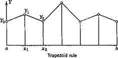
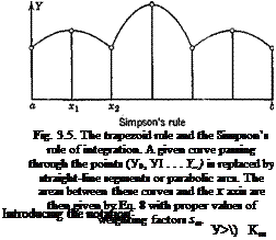
• 2 4 Ї

There are other more complicated rules which, however, are often inferior to the simple rules quoted above, save for exceptional cases. Represented graphically, these rules are illustrated in Fig. 3.5. Equation 8 can be written as a matrix product

fy(x)dx = hsY (9)

Ja

where Y is a column matrix, s is a row matrix of “weights,” and h is a constant:

Y0

Подпись: яг= 6 Yi

Similarly, a function of two variables K(x, y) can be represented as a double-entry table. Let the domain of (x, y) be the square (a < x, у < b), and let the interval (a, b)2 be divided into n2 subdivisions by the points

Уо = а, yn = b

xo — at xl> ‘ " "> Xn—1* Xn — ^

NUMERICAL APPROXIMATIONS — REDUCTION OF INTEGRAL EQUATIONS INTO MATRIX EQUATIONS


NUMERICAL APPROXIMATIONS — REDUCTION OF INTEGRAL EQUATIONS INTO MATRIX EQUATIONS

(И)

(12)


we may write


І’ЬК(х, у)ф{у)<іу = ЖБФ

Ja


where

кп

• •

• к1п

Knl

Kn г

■ • кпп

Ф>

Подпись: (14)
NUMERICAL APPROXIMATIONS — REDUCTION OF INTEGRAL EQUATIONS INTO MATRIX EQUATIONS

ft is gven by Eq. 10, and S is a diagonal matrix of “weights”:

The integral equation

ф(х) — A f K(x, уЩу) dy =f(x)

Ja

is then replaced by the approximate matrix equation

Подпись:Ф – МКБФ = f

where f is a column matrix with elements (/г,/2, • • •,/„)■

The matrix equation 15 can be made a starting point for a rigorous treatment of integral equations. The mathematical theory has been completed by Volterra, Fredholm, Hilbert, and others.

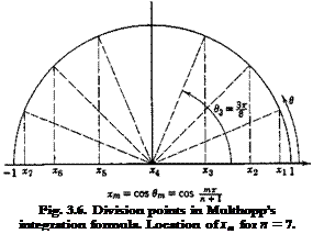
Подпись: Fig. 3.6. Division points in Multhopp’s integration formula. Location of xm for n = 7.

In Eqs. 8, 9, and 12 it was assumed that the intervals between the sub­divisions (xt — xt_j) are equal. In some cases it is advantageous to use

unequal subdivisions, such as in Gauss’s integration formula (cf. p. 159 of Ref. 3.21 or p. 115 of Ref. 3.23). However, in aeroelastic problems involving airplane wings, it is usually advantageous to use Multhopp’s

Подпись: and NUMERICAL APPROXIMATIONS — REDUCTION OF INTEGRAL EQUATIONS INTO MATRIX EQUATIONS Подпись: (16) (17)

formula which emphasizes the wing-tip regions. Multhopp’s formula,4-51 as is known in the theory of lift distribution, is

NUMERICAL APPROXIMATIONS — REDUCTION OF INTEGRAL EQUATIONS INTO MATRIX EQUATIONS Подпись: (18)

This formula holds exactly so long as the function Y(x) can be represented by a series of the following form:

Clearly, with a suitable modification of the constants slt • • -, ^r„ the method of reducing an integral equation into a matrix equation remains the same for unequal subdivisions (cf. sections on “divided differences,” pp. 20, 96, 104, Ref. 3.21).

3.4 CONCLUDING REMARKS

Throughout this chapter the aerodynamic moments have been based on the “strip” assumption. Relaxation of this assumption leads to compli­cated equations. For a normal wing without appreciable sweepback angle, the over-all effect of finite-aspect ratio on the divergence speed can be accounted for by taking the lift-curve slope a corrected for aspect ratio.

The effect of compressibility can be included by using proper aero­dynamic coefficients which correspond to the Mach number at which divergence occurs. The calculation can be made by a process of trial and error.