Category BASIC HELICOPTER AERODYNAMICS

Wind Tunnel Test Results

To examine the real effects of descent rate on the vortex wake streaming from a rotor the results of a wind tunnel test on a model rotor are presented.

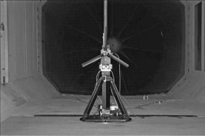
The model installation is shown in Figure 2.19.

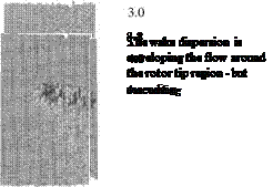
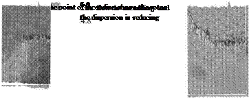
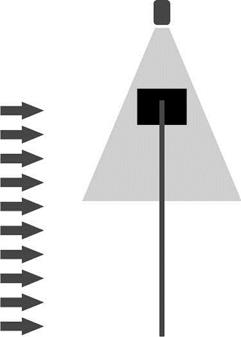
A particle image velocimetry (PIV) study was performed which enables laser light to be used to determine the flow velocity components in a geometric plane which is that swept out by the laser light beam – see Figure 2.20. In this experiment, the plane is normal to the rotor disc plane and includes the outer end of the blade and the initial part of the vortex wake. The velocity data are processed to give the vorticity variation across a part of the plane. Table 2.2 shows the vorticity maps for a range of wind speeds, which are effectively the descent rate of the rotor. For scaling purposes, the hovering induced velocity takes the value of 1.1 m/s.
The rotor rig details are:

Rotor speed

1200 RPM

Rotor radius

254 mm

Blade chord

34 mm

Number of blades

3

Blade twist

Collective pitch

10°

Table 2.1 Rotor flow states in axial flight

In climb and hover the flow retains the streamtube concept. Throughout the length of the streamtube, the velocity is in a downward direction

Actuator disc theory can be applied with due regard to its inherent simplicity. This is known as the normal working state

At low rates of descent a toroidal type of vortical structure begins to form around the tip region. Actuator disc theory can be applied but this is the sensible limit of its use. There is a small amount of upward flow, relative to the rotor, but the majority is in a downward direction still

At moderate rates of descent – equivalent to the induced velocity in hover – the rotor becomes immersed in a large toroidal vortex type of structure. As already explained, this is a very unsteady type of flow state. Actuator disc theory is totally unsuitable for this situation. This is known as the vortex ring state. The velocity direction is varied across the rotor throughout this flow state

As the descent speed increases, the wake now begins to move above the rotor. Its characteristics are similarto the wake behind acircular disc, hence its name – the turbulent wake state. There is still a difference in velocity direction. It is difficult to justify using actuator disc theory unless the descent velocity is approaching twice that of the induced velocity in hover

As the descent rate increases further, the wake is now moved further above the rotor and the velocity is now upward throughout. The streamtube concept is now appropriate. Actuator disc theory can be applied with due regard to its inherent simplicity. This is known as the windmill brake state

The illustrations show the gradual transition from a hover flow state to that of a descending windmill brake state. The character is a balance of clean wake flow at each end of the table and that of a dispersing wake where the vortex ring state region is found. It should be emphasized that the illustrations are a mean flow. The vortex ring state is a very unsteady flight regime and this must be borne in mind.

Figure 2.19 Rotor rig in wind tunnel

Table 2.2

Vorticity maps for a range of axial wind speeds

Vz/Vo

PIV image Vz/V0

PIV image

0

Подпись: 1.6

Table 2.2 (Continued)

VZ/V0 PIV image VZ/V0 PIV image

Descent

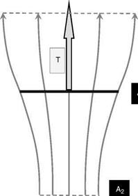
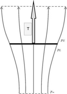
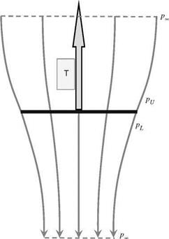
In modelling the actuator disc in descent, the air enters the streamtube from below the rotor with velocity VD and then acquires a reduction in velocity of V as it passes through the rotor disc. It finally forms the wake with a velocity decrease of V2. In this situation, the upward-going air has its velocity reduced as it passes along the streamtube from below the rotor to above the rotor where the wake forms. This is an effective increase in downward momentum of the air and this is how an upward thrust force can be generated from upward-moving air. The situation is shown in Figures 2.11-2.13.

Figure 2.12 Streamtube in descent


A


The rotor thrust force, T, can be evaluated by considering this momentum increase. With reference to Figures 2.11 and 2.12, the continuity of the flow through the streamtube can be expressed thus:

pAi (Vd-V2) = pA(VD-Vi) = M2(Vd) (2.36)

The rate of change of momentum gives the rotor thrust as:

T = pA(VD-Vi)V2 (2.37)

The thrust can also be expressed in terms of the difference of air pressure on both sides of the rotor disc – see Figure 2.13 – where we have the following:

T = A(pl-Pu) (2.38)

Подпись: pi + 2 p(VD—V2) Подпись: pu + 2 p(VD—Vi) Подпись: (2.39)

As before, Bernoulli’s equation can be applied to the flow above or below the rotor disc, but not through it. Above the rotor we have:

while below the rotor:

Подпись: (2.40)Pl + 2 P(Vd—vi)2 = Pi + 2 P(Vd)2

Подпись: PL—PU Подпись: 2 P(VD)2— 2 P(VD—V2)2 2 P(2VD—V2)V2 Подпись: (2.41)

Subtracting these gives:

Assembling (2.37), (2.38) and (2.41) gives the same result as in climb/hover, namely:

V2 = 2Vi (2.42)

from which we obtain from (2.37):

T = 2pA(Vd—Vi) Vi (2.43)

The streamtube modelling which was conducted for climb is now directed at descent. For the descent case, the velocity variation down the length of the streamtube again can be defined

relatively simply thus:

V = Vd-V + Vi • tanh(k0 (2.44)

where the terms are as used in the climb case (s is still positive downward).

The pressure variation now becomes as follows.

Above rotor:

Pi+ 1 P(VD-2Vi)2 = p + 2 PV

Подпись: (2.45)P-Pi _ (Vd-2Vi)2—V2 P 2

Below rotor:

Подпись:Подпись: 2(2.46)

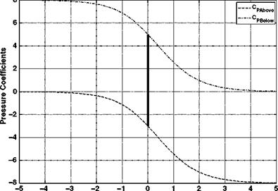
Using the pressure coefficient, based on the reference air velocity of U, we find the following results for the pressure variation for above the rotor (CPU) and below the rotor (CPL):

Подпись:(VD-2Vi)2-V2 Cpu = —U—

C _(Vd)2-V2 Cpl = U2

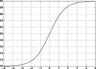
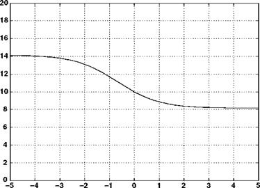
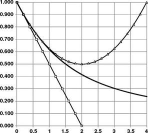
With a descent velocity of 30 m/s, an induced velocity of 10 m/s and a rotor radius of 10 m, the velocity, streamtube size and the pressure variation with axial location are as shown in Figures 2.14-2.16.

The results are similar to the climb case and the pressure jump required to generate the rotor thrust is again shown.

An examination of these two analyses might appear to give the impression that descent and climb are closely matched and that there would be no reason to foresee any difficulties. The analyses are beguiling. The sting in the tail is that actuator disc theory assumes a one­dimensional and incompressible flow. Therefore the flow direction must not change throughout the entire length of the streamtube – the constant mass flow guarantees this. In climb it must always be downward. For climb, Equation 2.32 guarantees this will happen. However, for descent, Equation 2.44 admits the possibility of a flow reversal. This begins to define the problems which are faced in modelling the lower descent rate of a helicopter rotor.

To see the potential problem, recall Equations 2.26 and 2.43. Collating the results and substituting to remove V2 terms we find the following.

Climb/hover:

Actuator Disc Theory – Descent ( VD = 30 Vi = 10 R = 10 )


Above Rotor – Streamtube Location – Below Rotor Figure 2.14 Axial velocity variation

Actuator Disc Theory – Descent ( VD = 30 V, = 10 R = 10 )


Подпись: Streamtube Radius

Above Rotor – Streamtube Location – Below Rotor


Above Rotor – Streamtube Location – Below Rotor


Figure 2.16 Axial pressure variation


Descent:


Подпись: (2.49)T = 2A • p(VD-Vi)Vi

If we now set the value of the climb/descent velocity to zero the situation of hover is achieved. Remembering that we denote the hovering induced velocity by V0, (2.48) and (2.49) become:

Подпись: (2.50)T = 2pA •

T = -2pA •

The upper (climb) equation produces a relationship which sensibly defines the hovering induced velocity as:

The second descent equation produces a conflict. The thrust force is always upward and must, therefore, always have a positive value. This cannot happen with this equation. This is an indication of a problem with actuator disc theory in descent – it cannot be extended to hover, leaving a domain which this equation cannot model. As will be seen, the theory works for
appropriate values of descent rate but, as just described, it cannot be extended back to the hovering condition.

Combining the results (2.51) with (2.48) and (2.49) gives:

Подпись: (2.52)= 2ТЇ =(Vc + V)V

V2 = IpA = (Vd-V)V

Подпись: VC VD Vi Подпись: VC V0 VD V0 V V0 Подпись: (2.53)

If we define the following normalized velocity terms:

and make the subst tut on:

Подпись: (2.54)Vd = – Vc

(so that both climb and descent use a common velocity sign convention), we obtain the following non-dimensional equations:

(Vc + Vi) Vi = 1

Подпись: (2.55)

(Vc + Vi )V =-1

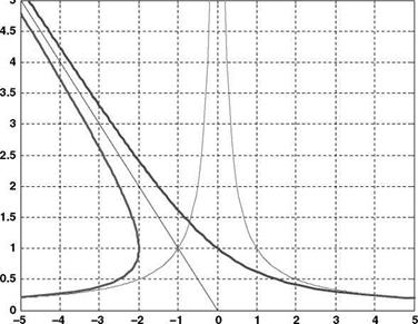
Equations 2.55 are then solved to give solutions for the induced velocity; however, only positive solutions are physically appropriate. A simple interpretation of these solutions can be obtained by re-expressing Equations 2.55 as:

Vc =± V – Vi (2.56)

These represent the sum of a rectified rectangular hyperbola and a linear function as shown in Figure 2.17.

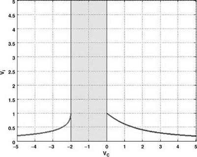
There is the requirement for the air to flow in one direction only (which was introduced earlier), and in order to satisfy this condition, limitations on the solutions must be made. Observation of the solutions shows that in order for the flow to be in the same direction at the entry, rotor disc and exit cross-sections of the streamtube, a region of axial velocity must be removed as shown in Figure 2.18.

Подпись: Vi

Vc


Figure 2.17 Solutions in axial flight


Where the limits on the vertical velocity are those which give a real mathematical solution, Equation 2.55 now becomes:

Подпись: (2.57)(VC + Vi) Vi = 1 , Vc > 0 (VC + Vi)V =-1 , VC <-2

It is therefore necessary to seek alternative solutions to the conditions experienced in this region. While this is relatively easy to write down, it is very difficult to handle theoretically. This is because the actuator disc relies on a definable streamtube while the flow conditions in the non­qualifying region are not in any way conducive to such a concept. Indeed, the actual situation isof a system of vortices being generated by the lifting rotor blades and becoming the dominant feature. In axial descent, at low speed, the downwash induced by the rotor and wake is matched by the upward motion induced by the descending rotor, resulting in the vorticity in the wake remaining in close proximity to the rotor disc. It is reasonable to observe that the rotor cannot store vorticity for ever and so there must some manner in which itcan disperse. In reality ittends to collect around the rotor giving rise to difficulties in handling and to act as a source of high – frequency vibration. Periodically, this collected vorticity releases, freeing up the rotor, whence the process can start again. This will contribute to the vibration by adding a low-frequency component to the previously mentioned high frequency. As can be envisaged, the airflow characteristics of a helicopter rotor, in what is termed the vortex ring state, are very complex and difficult flow conditions to model theoretically and have exercised many minds over the years.

Although these flight conditions are complex, it is instructive to consider what the mean flow behaviour would be. This directs the discussion to the various flow states that a helicopter rotor can experience as it moves from high-rate vertical climb to high-rate vertical descent.

These are presented schematically in Table 2.1.

Modelling the Streamtube

In order to investigate the concept, the velocity variation down the length of the streamtube needs to be modelled. Actuator disc (momentum) theory cannot give a precise solution to this velocity variation; however, a realistic and simple velocity variation can be defined thus:

V = Vc + Vi + Vi • tanh(k0 (2.32)

where s is the vertical location variable with the origin at the rotor disc centre – positive downwards; h is a distance defining the extent of the contracting streamtube above and below the rotor disc; and k is a factor which adjusts the severity of the contraction. The hyperbolic tangent function was used because of its asymptotic behaviour so the streamtube finishes as a cylinder far above and below the rotor disc.

Having defined the velocity variation, it is straightforward to determine the pressure variation: the pressure jump at the rotor disc means that the variation must be referenced to either end of the streamtube, far above and below the rotor, where the air pressure returns to ambient. So, using Bernoulli’s equation, we find that the pressure is given by the following two expressions (two are needed as described above).

Pi+; PVC = P + 2 Py2

Подпись: (2.33)

Above rotor:

pi + 2 r(vC+2Vi)2 = p + 2 pv2

Подпись:

Подпись: Below rotor:

p-Pi (VC + 2Vi)2-V2

p 2

Подпись: (2.35)

If we finally define a pressure coefficient, based on a reference air velocity of U, we find the following results for the pressure variation for above the rotor (CPu) and below the rotor (CPL):

with the following values:

Vz

10 m/s

Vi

10 m/s

R

10 m

U

10 m/s

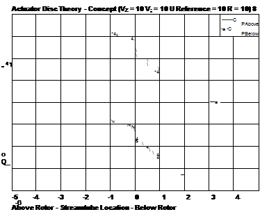
The velocity, streamtube size and the pressure variation are shown in Figures 2.8-2.10.

Actuator Disc Theory – Concept ( VZ = 10 V; = 10 R = 10 )

Above Rotor – Streamtube Location – Below Rotor


Actuator Disc Theory – Concept ( VZ = 10 V; = 10 R = 10 )

Above Rotor – Streamtube Location – Below Rotor

Figure 2.9 Axial streamtube radius variation


The velocity and streamtube radius follow from the foregoing discussion. However, the pressure variation requires some investigation. The pressure line for any location below the rotor lies above that for locations above the rotor. However, it must happen that the overall pressure variation must move, discontinuously, from one solution to the other. It is difficult to justify any movement from one line to another in the free air stream; however, a pressure jump may be successfully argued at the rotor disc. It is this pressure jump that determines the thrust achieved by the rotor and is shown in Figure 2.10.

The above discussion demonstrates the emergence of an actuator disc model which in reality cannot occur. It is not easy to envisage an airflow whose velocity is continuous but also undergoes a discontinuous pressure change at the rotor disc. Therefore one cannot buy an actuator disc; it is purely a conceptual device which describes in fairly good detail the helicopter rotor in axial flight (which includes hover). In the case of climb and hover, this method can be used quite successfully. Unfortunately, this straightforward method has a weakness as it is poor at modelling a descending rotor over a range of descent rates. This will now be investigated.

Axial Flight

When the rotor leaves the hovering condition and moves in a vertical sense the flow still remains symmetrical about the thrust force line, that is normal to the rotor disc. In climb, the situation is relatively straightforward to model; however, in descent problems arise. This comment is particularly focused on the use of a momentum-based theory. The flow details become very complex in a medium descent rate condition where the descent rate is of similar magnitude to the induced velocity in hover. A quick view of this type of condition sees opposing flows at the rotor disc of similar magnitude. In order for a momentum theory to be applicable, there must be a realistic throughput of flow along the entire streamtube length. The first situation to be investigated is climb.

2.2 Momentum Theory for Vertical Climb

Consider the rotor in climb, where, again, we observe the flow from the point of view of the rotor. The flow enters the streamtube far upstream of the rotor (because of the climb velocity the streamtube has a finite cross-section), and then passes through the rotor itself, finally passing away from the rotor forming the wake. As a momentum change must be generated, and also making the assertion that the rotor is producing a thrust force in a vertically upward direction, the air will accelerate towards the rotor disc as it approaches from the upstream direction and then accelerate further as it moves downstream into the wake. In order to analyse this situation, the flow velocities are shown in Figure 2.3, the streamtube cross-sectional areas in Figure 2.4 and pressures in Figure 2.5.

The air enters the streamtube with velocity VC and then acquires an additional velocity of Vi as it passes through the rotor disc. It finally forms the wake with a velocity increase, from Vc, of V2.

The rotor thrust force, T, can be evaluated by considering the momentum increase. The continuity of the mass flow through the streamtube can be expressed thus:

Mi (Vc) = M(Vc + Vi) = M2(Vc + V2) (2.20)

The rate of change of momentum gives the rotor thrust as:

Подпись: (2.21)T = pA(Vc + Vi)V2

Equation 2.21 represents the mass flow with the velocity increase down the entire length of the streamtube.

As discussed in the hover analysis, the thrust can also be expressed in terms of the difference of air pressure on both sides of the rotor disc – Equation 2.3. Again, the final consideration is the

pL + 2 p(VC + Vi)2 — Pi + 2 p(VC + V2)2

pL ^pU — 2 p(VC + V2)2 2 P(Vc)2

1

— 2 p(2Vc + V2)V2

Assembling (2.3), (2.21) and (2.24) gives:

Figure 2.5 Pressure variation


application of Bernoulli’s equation. Above the rotor we have:

1 2 1 / ,2 Pi + 2 pvc — pu + 2 p(Vc + Vi)


(2.22)


while below the rotor:


(2.23)


Subtracting these gives:


(2.24)


Substituting (2.25) into (2.21) we find:

Подпись:Подпись: (2.27)T = 2PA(Vc + Vi) Vi

from which we obtain:

v2 + Vc • vi-2ГА = 0

Vi2 + Vc • Vi-V2 = 0

*Y + Vc • V-1 = 0

V0 V0 V0

Подпись: V, V0 Подпись: (2.28)

(we denote the induced velocity in hover for the same thrust as V0) with solution:

Подпись: (2.29)

If the climb rate is relatively low, then (2.28) can be expanded to give:

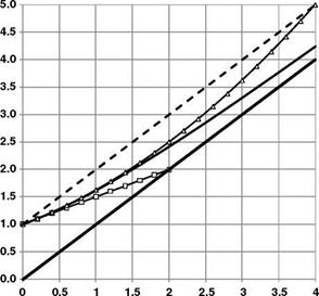
The variation in the solution and the various approximations is shown in Figure 2.6.

The first-order solution can be used for small climb rate ratios up to 0.2, the second order can be used to a value of 1.0. Exceeding these limits will give a spurious result.

The power consumed is now given by the product of the thrust and the total velocity through the rotor disc, that is:

P = T (Vc + Vi)

= T • Vc + T • Vi

(2.30)

= P CLIMB + P i

P

T = Vc + Vi

We have the induced power as before but the climb power is now added.

Considering the last equation of (2.30), the variation of the power thrust ratio (relative to the hover value) is shown in Figure 2.7.

Подпись: (Vc+Vi)/Vo Vi/Vo

— Full Solution – o – O(1)

^ O(2)


Vc/Vo


Figure 2.6 Solutions


Full Solution -°-O(1) -*“O(2)

— — Constant Climb Only


Vc / Vo


The full solution and the two approximations are shown. In addition, the variation of the climb-only power ratio and the total power ratio – assuming no change in the induced velocity – are also shown. The limitations of the approximations are as before; however, the climb-only and constant induced-velocity lines bracket the full solution. As the rotor begins to climb, the mass flow entering the rotor increases and with a constant thrust the momentum generation can be achieved with a lower induced velocity – hence the reduction in the induced power. This means that the power to climb steadily is eased by this reduction in induced velocity. In the limit, when the climb rate becomes extremely large, the induced velocity asymptotes to zero.

Подпись: CP Подпись: (2.31)

In non-dimensional terms these results become:

Figure of Merit

The induced power Pi is the major part of the total power absorbed by a rotor in hover. A further power component is needed, however, to overcome the aerodynamic drag of the blades: this is the profile power Po, say. Since it is the induced power which relates to the useful function of the rotor – that of producing lift – the ratio of induced power to total power provides a measure of rotor efficiency in the hover. This ratio is called the figure of merit, commonly denoted by M. Using the results of simple momentum theory, M may be variously

Подпись: (2.15)ideal induced power actual induced power

Pi

kipi + pP

Equation 2.15 contains a number of considerations. Firstly, there is the fact that, so far, the induced power is considered ideal. The fixed-wing world has a similar situation where the overall drag of the wing is being considered. The induced drag component has a minimum value when the wing is elliptically loaded. This condition also gives a constant downwash behind the wing. Under the majority of circumstances, a wing is not precisely elliptically loaded and so the downwash will vary across the wing span and an induced drag in excess of the minimum will be encountered. This is catered for by means of a factor applied to the induced drag. With the helicopter rotor, the downwash, or induced velocity, has been assumed constant and so the actuator disc provides the ideal solution. In reality there will be a variation in the induced velocity and so a factor (induced power factor ki) is applied. The fixed wing also generates a profile drag force due to skin friction, independent of any wing lift. The helicopter rotor also incurs a power requirement to overcome skin friction forces on the blades. The variation of the velocity over the blades requires a short integration to be undertaken, but the profile power is given by:

1

Pp = – pVT • NcR • Cd0 (2.16)

8

The expression contains an area term, which is the blade area. This is because of the way the profile drag is determined by the forces on the blades. In order to align with the induced power normalization the following expression for the profile power coefficient results:

– pVT • NcR • Cdo

Cpp =

2 pVT •A (2.17)

1 NcR

– 4 ^ ^ Cd0

Equation 2.17 contains the ratio of blade area to disc area. This is known as the solidity of the rotor and is denoted by s or sometimes s. The former will be used in this book and can take several forms thus:

NcR

Подпись:~A~

Подпись:

Подпись: expressed as:

NcR

pR2

Nc

pR

Equation 2.15 can be rewritten using these non-dimensional quantities thus:

Подпись: M Подпись: (2.19)

kicT • Ai + 4 • Cd0

(Ct )3=2

ki • (Ct)3=2 + 2 • Cd0

Подпись: k = 1.1 I Solidity = 0.1 I CD0 = 0.011 CT

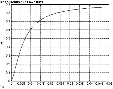
Now for a given rotor blade the drag coefficient, and hence the profile power, may be expected not to vary greatly with the level of thrust, provided the blades do not stall nor experience high-compressibility drag rise. Equation 2.19 shows therefore that the value of M for a given rotor will generally increase as Ct increases (this is illustrated in Figure 2.2). This feature means that care is needed in using the figure of merit for comparative purposes. A designer may have scope for producing a high value of M by selecting a low blade area such that the blades operate at high lift coefficient approaching the stall, but they need to be sure that the blade area is sufficient for conditions away from hover, such as in high-speed manoeuvre. Again, a comparison of different blade designs – section shape, planform, twist, and so on – for a given application must be made at constant thrust coefficient.

A good figure of merit is around 0.75, the profile drag accounting for about one-quarter of total rotor power. We may note that for the helicopter as a whole, some power is also required to drive the tail rotor, to overcome transmission losses and to drive auxiliary components: as a result the induced power in hover amounts to 60-65% of the total power absorbed.

Non-dimensionalization

In assessing rotor performance and the ability to compare calculations or different rotors, non­dimensional quantities are useful. The induced velocity is normalized using the rotor tip speed, VT. The velocity varies along the entire rotor blade but the tip speed is the defining value. In fixed-wing terms this problem does not arise, since the entire wing sees the same velocity. This defines the non-dimensional induced velocity thus: [3]

Подпись: T 1 2 2 rvT • A pR2 Подпись: (2.11)

rotor blade tips (in hover) and the area is the total disc area. A fixed wing uses the planform area which in a helicopter rotor would be the planform area of the blades. While this will be used later, with momentum theory the blades are not considered, so the overall rotor disc area is appropriate. The thrust coefficient is then defined by:

The inclusion of the half in the denominator is consistent with the lift coefficient definition for a fixed-wing aircraft. However, the inclusion of the half is not universal. The reader is urged to always check the definition of the thrust coefficient if they are consulting any technical documentation. An error here is both annoying and potentially very serious. Combining (2.8), (2.10), (2.11) gives the following non-dimensional equation:

Подпись:1 — 2 v/CT

Ct — 41?

Подпись: СРІ Подпись: (2.13)

The induced power coefficient is also normalized – noting the inclusion of an extra velocity (tip speed) in the denominator to balance the units:

Combining (2.9)-(2.13) gives:

Подпись: (2.14)

CPi — Ct •1

Rotor in Vertical Flight: Momentum Theory and Wake Analysis

We begin examining rotor aerodynamics by building models based on momentum transfer – see Glauert [1]. This allows the essential performance of the rotor to be assessed. The most straightforward flight condition is hover, which provides the first part.

2.1 Momentum Theory for Hover

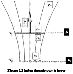
The simplest method that describes the lifting rotor is actuator disc theory. It is based on achieving a lifting force by generating a change of momentum. It assumes the existence of a streamtube which is an axially symmetric surface passing through the rotor disc perimeter which isolates the flow though the rotor. The air is assumed to be incompressible and therefore the flow past any cross-section of the streamtube is constant (Figure 2.1). This also means that because the flow is one dimensional, the flow must remain in the same direction, which for most flight conditions is appropriate. However, this does give rise to a failing of the theoretical model under certain flight conditions.

The flow enters the streamtube, is accelerated through the rotor disc and then is exhausted from the bottom of the streamtube. Far upstream of the disc, the vertical flow velocity must tend to zero making the streamtube cross-section infinite in size. However, the streamtube establishes itself and passes through the rotor disc perimeter.

The additional velocity of V as it passes through the rotor is known as the induced velocity. It finally forms the wake with a velocity increase of V2.

The rotor thrust force, T, can be evaluated by considering the momentum increase. The continuity of the flow through the streamtube allows the following:

Подпись: (2.1)pA • Vi = pA2 • V2

Basic Helicopter Aerodynamics, Third Edition. John Seddon and Simon Newman. © 2011 John Wiley & Sons, Ltd. Published 2011 by John Wiley & Sons, Ltd.

Подпись:
The rate of change of momentum gives the rotor thrust as:

T = pAVi • V2 (2.2)

Every second a packet of fluid enters the streamtube with zero vertical velocity. In that same second, an equal packet of fluid leaves the streamtube with a vertical velocity ofV2. Hence, in every second there is a momentum generation given by (2.2).

Actuator disc theory also uses the fact that the thrust can also be expressed in terms of the difference of air pressure on both sides of the rotor disc. In order to generate a thrust, there has to be a pressure difference, which is discontinuous since the rotor disc has zero thickness. However, the airflow through the rotor is continuous and forms part of the theoretical premise of the actuator disc.

We therefore have the following:

T = A(pl-pu) (2.3)

Подпись: pi Подпись: pu + 2 PVi Подпись: (2.4)

The final consideration is the application of Bernoulli’s equation. This equation can be applied to the flow above or below the rotor disc, but not through it. Above the rotor we have:

while below the rotor:

Подпись:1 , 1 , pl + 2 PVi = P1 + 2 PV2

Подпись: PL-PU Подпись: pVl Подпись: (2.6)

Subtracting these gives:

Assembling (2.2), (2.3) and (2.6) gives:

V2 = 2| (2.7)

In other words, the induced velocity is doubled as the air forms the wake far downstream of the rotor.

Подпись: Vi Подпись: v^A ГА Подпись: (2.8)

Combining (2.2) and (2.7) gives the following result:

The second expression shows that the induced velocity is dependant explicitly on the disc loading T/A.

Equation 2.8 provides the link between disc loading and induced velocity. At first sight, all this would seem to indicate is that the higher the disc loading, the greater the downdraught from the rotor. Correct, but not the real punchline. The thrust force is working on a medium passing through it at the induced velocity, V). Therefore the rotor is expending power (product of force and velocity) given by:

Подпись: (2.9)Pi = T • Vi

This power is given a suffix of ‘i’ consistent with the induced velocity. This is because this power is termed the induced power and is a result of generating the thrust force. If we now compare various rotors, it is apparent that the higher the disc loading, the higher the induced power. As will be shown later, the induced power forms the majority of the power consumed in hover, which is itself a high power-consuming flight regime. The disc loading is therefore one of the first items to be considered when designing a rotor system. Apart from the maximum all-up weight of the helicopter, the main rotor size is almost the first decision to be made.

Book Presentation

It will be helpful to explain certain logistics of the presentation. Symbols are defined when first introduced but for ease of reference are also collected in a list at the start of the book. As concerns units, where there is complete freedom of choice the metric system is preferred; since, however, much use continues to be made of imperial units, particularly in the USA, I have also employed these units freely in numerical examples, sometimes giving both. Again there are tables at the start defining primary and derived units and listing the conversion factors. Lastly, on the question of references, these are numbered in each chapter and listed at the end of the chapter in the usual way. Exception is made, however, in the case of six standard textbooks, which are referred to repeatedly, usually for further information on a topic where the present short treatment is deemed to have gone far enough. The books are:

1. Bramwell, A. R.S. (1976) Helicopter Dynamics, Edward Arnold.

2. Johnson, W. (1980) Helicopter Theory, Princeton University Press.

3. Stepniewski, W. Z. and Keys, C. N. (1984) Rotary-wing Aerodynamics, Vols I and II, Dover.

4. Leishman, J. G. (2006) Principles of Helicopter Aerodynamics, 2nd edn, Cambridge Aerospace Series, Cambridge University Press.

5. Padfield, G. D. (2007) Helicopter Flight Dynamics: The Theory and Application of Flying Qualities and Simulation Modelling, 2nd edn, Blackwell.

6. Cooke. A and Fitzpatrick, E. (2002) Helicopter Test and Evaluation, Blackwell.

In the texts, these are called upon by author’s name and no further reference is given.

With this brief introduction we are poised to move into the main treatment of our subject. Finally I would like to mention the following text, which is a source of valuable historical information on helicopters – Boyne, Walter J., Lopez, Donald S. (1984) Vertical Flight – The Age of the Helicopter, Smithsonian Institution Press.

Reference 1. Jones, J. P. (1973) The rotor and its future. Aero. J., 751, 77.

The Helicopter from an Engineering Viewpoint

It is easy to invent a flying machine; more difficult to build one; to make it fly is everything.

Otto Lilienthal, 1848-1896

Lilienthal was a pioneer of gliding flight; however, the above quote makes the reader ponder whether he had the helicopter in mind when he wrote it. So far in this chapter, the road to the modern helicopter is anything but straight, so if we examine the quotation line by line, the concept of a lifting rotor constitutes the essential invention. Making it of large radius is simply taking advantage of Newton’s second and third laws, which guarantee that in generating a thrust force, by imposing a momentum change on the air, the use of a large quantity of air allows a low – speed change in the air which can be proved to be an efficient way of producing a thrust. When it comes to building the flying machine, the problems of directing it around the sky have to be thought out and translated into hardware: ultimately, however, the solutions for the helicopter are both straightforward and impressive. Upward lift is obtained with the rotor shaft essentially vertical; forward (or backward or sideways) propulsion is achieved by tilting the rotor plane in the desired direction (the rotor shaft itself is tilted in several early designs). This tilting of the rotor disc plane permits moments about the helicopter centre of gravity to be produced, which provides for manoeuvring. Here is a system more elegant in principle than that of a fixed-wing aircraft, where such integration of functions is not possible. However, the combining of several features of rotor control in one function causes its own difficulties.

One can pursue the helicopter rotor’s virtues one stage further by noting that the direction of airflow through the rotor becomes reversed in descent allowing blade lift to be produced without power (‘autorotation’), permitting a controlled landing in the event of engine failure. This is the point where the heredities of helicopter and autogyro merge and their place on the family tree is defined. These points were made by J. P. Jones in the 1972 Cierva Memorial Lecture to the Royal Aeronautical Society [1]. To quote him at this juncture:

Can we wonder that the conventional rotor has been a success? At this stage one might think the real

question is why the fixed-wing aircraft has not died out.

If we now return to Lilienthal we see the difficulty. Making the helicopter fly involves wrestling with a long catalogue of problems, some of which have been solved while there are others still to be solved – helicopters will always remain an intriguing challenge. During the gestation of the helicopter, it was necessary to invent the use of a tail rotor to stop the helicopter spinning round on the main rotor axis. To this is added other mechanisms of controlling the helicopter in yaw. It took the genius of Juan de la Cierva to devise a system of articulated blades to prevent the aircraft rolling over continuously – his earlier working life involved structures, where the use of a pinned connection to isolate moments provided an ideal grounding. While it can take off, land and hover efficiently, the helicopter can never fly fast judging by fixed-wing aircraft standards, the restriction, surprisingly enough, being one of blade stalling. Climbing is straightforward aerodynamically but descending involves a deliberate venture into the aerodynamicist’s nightmare of vortices, turbulence and separated flow. The behaviour of vortices left by an aerodynamic device is crucial to its performance and the locations of these vortices are critical.

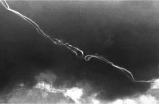
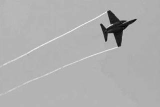
As an example, Figure 1.18 shows the location of a typical wake from a fixed-wing aircraft (AlphaJet) where the wing tip vortices stream behind the aircraft and are shown condensed water vapour acting as a tracer.

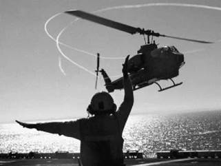
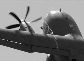
Figure 1.19 shows vortices being left by the propeller blade tips of an Alenia C27J aircraft and how they wash over the inboard wing structure. To examine a situation in the rotorcraft world, Figure 1.20 shows the vortex wake off a helicopter rotor (AH-1W). Close examination of the wake structure shows interaction with the tail rotor and the rear fuselage.

In addition to influencing any lifting surfaces, vortices interact with each other. Figure 1.21 shows the wake from the wings of a BAE Systems Hawk 200 aircraft after a tight pull-up

Figure 1.18 Tip vortices generated by a fixed-wing aircraft

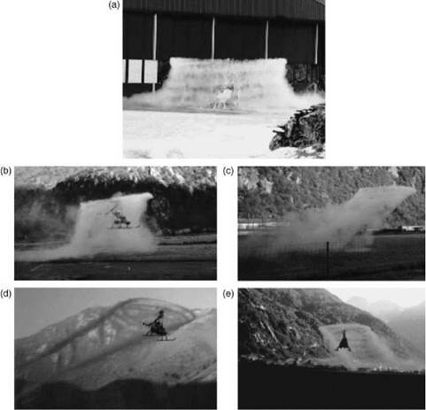
manoeuvre. The two tip vortices have closed together and on bursting (an unstable breakdown of the initial vortex structure) are beginning to form the characteristic loops associated with parallel pairs of vortices. Figures 1.22a-e show a sequence of images of a small helicopter with a tip-driven rotor. The tip jet uses fuel which produces a considerable amount of water vapour and, using this as a tracer, the exhausts show the wake structures in several different flight regimes.

Figure 1.22a illustrates a hovering condition close to the ground surface. The wake can be seen to contract immediately below the rotor but then expand as the downflow from the rotor is interrupted by the ground forcing it to spill outwards. This phenomenon is called ‘ground effect’ and is a very important feature of helicopter performance. The wake structure shows not only the ‘tube’ of vorticity, but also the individual blade tip vortices. Figure 1.22b shows the rotor at low forward speed. Ground effect is still present but the wake is now dispersed rearwards. As the forward speed increases, Figure 1.22c, the vortex ‘tube’ adopts a sheared profile for a short distance before mutual interaction between the vortices begins to distort the wake. The sheared

Figure 1.20 Rotor blade tip vortex trajectories (AH-1W) (Courtesy Safety Centre US Navy)

vortex tube concept is a useful modelling technique but, with vortex interactions, as shown in Figure 1.22c, needs care in application. As forward speed increases further, the individual wake vortices show a cycloidal shape (in plan) and a roll-up character at the lateral rotor disc edges, not unlike a fixed wing. These characteristics are well shown in Figures 1.22d and e. In order to provide rotor control, previous discussion has highlighted the necessity of allowing the blades to move out of the plane of rotation. ‘Blade articulation’ is the term used for the use of conventional rotational hinges and this can lead to comparatively sluggish control since it is really the rotor thrust line change which can impart a turning moment to the helicopter, the free blade attachment hinges contributing very little. This can be significantly improved by adopting the principle of a hingeless rotor where the blade attachment is a flexible component. This can now provide a significant addition to the rotor thrust effect and obtain a greater turning effect for the helicopter. However, this situation isa double-edged sword since the improvement in the path for controlling the helicopter also applies to vibration and other adverse effects such as worsening aircraft

Figure 1.22 Rotor wake development (Courtesy ATI Corporation): (a) hover in ground effect (IGE); (b) hover IGE to out of ground effect (OGE); (c) low forward flight speed; (d), (e) high forward flight speed

stability. With any practical combination of stability and control characteristics the helicopter remains a difficult and taxing aircraft to fly and generally requires autostabilization to restrict the pilot workload to a safe and comfortable level.

It would seem that we have on our hands a veritable box of tricks. What is certain, however, is that the modern world cannot do without the helicopter. It has become an invaluable asset in many fields of human activity and the variety of its uses continues to increase.

Moreover, to come close to the purpose of this book, the problems that have been solved, or, if only partly solved, at least understood, make good science, high in interest value. This, the book purports to show.

Up to the present, the single-rotor helicopter remains by far the most numerous worldwide and in this book we concentrate exclusively on that type. Its familiar profile, sketched in Figure 1.23, is the result of practical considerations not readily varied. The engines and gearbox require to be grouped tightly around the rotor shaft and close below the rotor. Below them the

Figure 1.23 The basic structure of a single-rotor helicopter

payload compartment is centrally placed fore and aft to minimize centre of gravity (CG) movements away from the shaft line. In front of the payload compartment is the flight cabin. The transmission line from gearbox to tail rotor needs to be as straight and uninterrupted as possible. Put a fairing around these units so defined and the characteristic profile emerges.

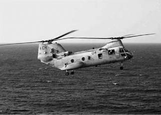
Of the other helicopter configurations, the tandem is the next to consider – a typical example, a Boeing Vertol H46 Sea Knight, is shown in Figure 1.24.

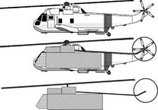
As shown in the figure, there are two rotors, placed at each end of the fuselage. They rotate in opposite senses so the aircraft will respond in yaw to the difference in torques from both of the rotors and a tail rotor is not used. The rear rotor is placed on a pylon so that in normal flight it is not immersed in the wake from the front rotor. This difference in rotation planes gives rise to interactions between translation and rotations during particular flight phases – but these are well known and appropriate action takes place. The figure shows the aircraft decelerating to a hover and to do this the entire aircraft is in a nose-up attitude. As can be seen, the rear rotor is

Figure 1.25 Mil 12 (Courtesy Agusta Westland)

now moved towards the downwash of the front rotor and this can give rise to a sinking of the rear of the fuselage unless appropriate thrust changes are made. The location of the rotors at each end of the fuselage gives this configuration a wide CG range which for the single main and tail rotor configuration is very limited. The transmission is more complicated as the rotors must be kept in synchronization as the rotor discs overlap. Typically it consists of the engines supplying a combiner gearbox from which individual shafts supply the necessary torque to the rotors.

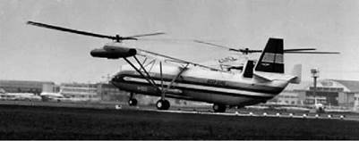
In the side-by-side configuration, there are a pair of contra-rotating main rotors, but in this configuration they are located laterally on pylons. Yaw control is by differential torque, but for this configuration the CG range is now in a lateral sense. A good example of this type is the Mil 12 shown in Figure 1.25.

This aircraft was designed, in the days of the Cold War, to carry large missiles and the lateral arrangement of the rotors gives a reduced interference between the rotors for an improved performance. The rotors require cross-shafting to keep them synchronized. The Mil 12 was described as appearing to swim through the air with the rotors advancing along the centre looking as if they are executing the breaststroke.

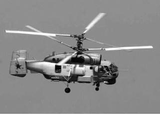
In the coaxial configuration, the rotors are contra-rotating but rotating about a common shaft. An example is the Kamov shown in Figure 1.26.

Figure 1.27 Kaman KMax (Courtesy Marcus Herzig)

As can be seen, the rotor controls have to pass along the same axis so the upper rotor controls have to pass though those of the lower rotor. The rotors are articulated and so the effect of forward speed will tend to tilt the discs rearwards and laterally in opposition so that on one side of the rotor the blade tips are moving together. To avoid any chance of a blade clash, the rotor hubs are separated by a relatively long rotor mast. This gives rise to an increase in drag. With no tail rotor and a compact footprint, they are very useful in shipborne operations.

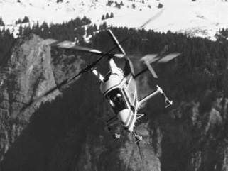
The helicopter company Kaman has for years used a dual-rotor system which occupies not much more than a rotor disc but uses two rotor shafts inclined to the aircraft’s central plane. The most recent of these aircraft is the KMax as shown in Figure 1.27.

The rotors have two blades and are phased by 90° which permits the rotors to pass without mechanical interference. Like the coaxial layout, this compact arrangement permits use in confined spaces. It has therefore contributed much effort in shipborne roles and those with very limited operational areas such as forestry.

The above discussion is concerned with proper helicopter types. If the restriction is lifted then other configurations can be examined, two of which are the tilt rotor and tilt wing.

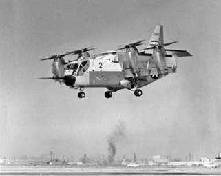
The classic tilt wing is the Ling-Temco-Vought XC142 as shown in Figure 1.28.

The rotor(s) have been replaced with propellers, two on each wing. The entire wing/engine/ propeller layout rotates through 90° so that vertical take-off and landing can be achieved with a conventional lifting through the propeller thrusts and revert to conventional wingborne flight by rotating the wing assembly back to horizontal. With the addition of wing devices such as flaps, the mechanical side of this arrangement is complex. The wing chord is always aligned with the propeller thrust line and so the slipstream can pass smoothly past the upper and lower surfaces. Transition is a difficult flight regime, particularly coming in to land when the wing is positioned with a high pitch angle and the supporting lift is being transferred to the propellers. Wing stall is a potential problem.

The more common tilt rotor variant only tilts the rotor/engine nacelle assemblies leaving the wing in a fixed position relative to the fuselage. The transition from the wing to the rotors is not applicable here, but in and around the hover, the rotor downwash is interrupted by the wing which will be close to a right angle to the flow. This will generate considerable download which

Figure 1.28 LTV XC 142 tilt wing (Courtesy McDermott Library, University of Texas)

is exacerbated by the central parts of the downwash flowing inward along the wings and then forming a fountain flow which creates a larger download still. The use of wide chord flaps aligned vertically reduces the area facing the rotor downwash. A recent example of this type of rotorcraft is the Bell Agusta 609, shown in Figure 1.29.

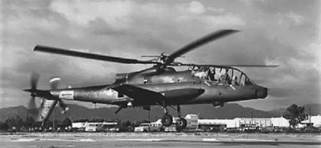
The final configuration to be highlighted within the helicopter family is the compound helicopter. There have been several companies who have pursued this variant, one of which, Piasecki, has already been mentioned in this chapter. Another landmark move into this type is the AH64A Cheyenne as shown in Figure 1.30.

This helicopter had a gyro-controlled main rotor; the tail rotor was located at the rear of a conventional tail boom alongside a pusher propeller. Stub wings were fitted to the fuselage, which gave this aircraft a fully compounded layout. They also provided an aerodynamic mounting for stores and ordnance.

Any further discussion of vertical take-off and landing (VTOL) configurations now leads into fan and jet lift which is moving away from the idea of rotorcraft and forms a natural halt to this discussion.

Figure 1.30 AH64A Cheyenne compound helicopter (Courtesy US Army)

Post-war Years

This period saw the emergence of a number of helicopter engineers whose names remain in the forefront of rotary-wing technology today. Bell had Arthur Young, who developed the Bell Bar system of rotor control. Frank Piasecki provided advancement of the tandem configuration with his own company where the compound configuration was added to the portfolio. Charles Kaman, also establishing his own helicopter company, took the Flettner type of rotor forward and also developed conventional rotorcraft layouts. His aircraft designs differed from the mainstream in that the rotor blade pitch control was achieved by using servo flaps placed on the trailing edge of the blades. This caused blade pitch change to be achieved via elastic twisting rather than using a pitch bearing at the rotor head itself. Another helicopter name was borne by

Figure 1.8 Bell 47 (Courtesy John Olafson)

Stanley Hiller. His helicopters used a method of rotor control where a servo paddle was placed underneath the rotor, in an orientation similar to the Bell Bar of Arthur Young. In the Soviet Union we have the names of Mil, Kamov, Yakovlev, Archangleis and Tischenko appearing.

The conditions under which helicopters could operate were extended by the development of de-icing to main and tail rotors, engine inlets, the use of radar altimeters, long-range navigation and Instrument Flight Rules (IFR). The loads carried by helicopter components were becoming heavier and so the move from forgings to castings was being made for rotor heads and transmission.

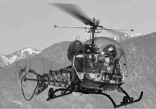
On 8 December 1945 the Bell 47 – see Figure 1.8 – made its first flight beginning a long contribution to helicopter development. In May 1946 we find the appearance of the first US commercial helicopter in the guise of the Bell 47 CAA Type Cert H-1.

In 1946 W. Laurence LePlage produced the XR1 side-by-side rotorcraft, which was notable since it extended to a tilt rotor configuration. Robert Lichten with the Guerierri Transcendental aircraft model 1G appeared the previous year and he eventually moved to Bell to take responsibility for tilt rotor development.

The year 1947 saw the first all-metal helicopter – the Kellett XR-10 – which became the first twin-engine rotary-winged aircraft for the US Air Force.

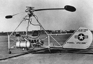
Later that year there was the appearance of the McDonnell XH-20 Little Henry – see Figure 1.9. This was the first tip-jet-powered helicopter to be driven by ramjets. This had the disadvantages of a high fuel consumption and noise production, a problem with tip-jet drives which surfaces later in the history of the helicopter.

The following year, in August, saw the Sikorsky S52 become the first helicopter to use all­metal rotor blades. The following month, the Mi-1 (Hare) became the first mass-produced Soviet helicopter.

In 1949, a Hiller Model 12flewthefirsttranscontinentalflightacross theUSAby acommercial helicopter. Also that year, in the UK, the first commercial helicopter began operation after the Bristol Type 171 Sycamore gained a commercial certificate of airworthiness.

In Europe, it was considered that Second World War designs could not be developed satisfactorily, so in 1945 England and France promoted new helicopter concepts. In 1950 Fairey considered the Doblhoff concept of the tip jet. It produced the Fairey Ultralight which

Figure 1.9 McDonnell ‘Little Henry’

was successfully demonstrated landing and taking off from a lorry at the Farnborough Air Show. This design was stopped in favour of the W14 Skeeter being produced by the Cierva Autogyro Company in Eastleigh/Southampton in England. The Cierva Company had produced its W9 helicopter – see Figure 1.10 – in 1946, which had a novel feature in the tail design. Rather than a conventional tail rotor for torque reaction, it used the tail boom as a plenum chamber and expelled air via a sideways-facing jet. This concept is now used today as the NOTAR system. It also used a different concept for main rotor control. The blades were attached to the hub with a fixed pitch angle which places thrust control on the rotor speed and has the inherent problem of a high rotor inertia preventing rapid changes in rotor speed and hence rotor thrust. The main rotor disc attitude was controlled by physically orientating the main rotor hub into the rotation

Figure 1.11 W11 Air Horse (Courtesy Solent Sky)

plane required – as already described. This required a significant effort from the pilot and powered controls were needed.

The W11 Air Horse was revolutionary in that it had three main rotors. A rather unusual layout, it was born of a combination of the tandem and side-by-side rotor layouts. It flew from Southampton but ultimately suffered a crash near Romsey about 10 miles from Southampton in June 1950. Figure 1.11 shows the Air Horse.

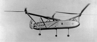
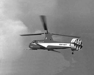
Fairey Aviation Co. produced a sequence of novel helicopter designs starting in 1947 with the Gyrodyne. This belonged to a type of helicopter known as a compound. In these designs, the main rotor forward propulsion is augmented by a separate propulsive device. In the Gyrodyne, the main rotor torque reaction was achieved with a forward-facing propeller placed on the starboard side of the fuselage. This also generated a forward propulsive thrust. In 1948 it set the world speed record at 200 km/h. In 1954-1955 Fairey developed the Jet Gyrodyne, which hovered for the first time in 1957 and into transition in 1968. The final development by Fairey was the Rotodyne – see Figure 1.12. This was a true convertiplane and demonstrated how one airframe could use powered rotors for vertical take-off and landing but perform transitions to and from autogyro-type forward flight.

The 1950s and 1960s decades saw many firsts. In June 1950 the world’s first scheduled helicopter passenger service was flown by a British European Airways S51 helicopter. Maiden flights were several: namely, the first turbine helicopter – Kaman K225 in December 1951; the first production rotorcraft with retractable undercarriage – Sikorsky S56 Mojave; the first twin – turbine helicopter – Kaman HTK-1 Huskie; the first Soviet production helicopter – Mi 6 Hook; and the development of the flexstrap rotor hub by Hughes.

In 1962, a Sikorsky S61 was the first helicopter to achieve over 200 mph in level flight; in 1963, the Alouette became the first commercial turbine helicopter in the USA; and in September 1965, the Bell AH1 Cobra became the first dedicated US attack helicopter.

In this period of time several aircraft appeared with the designation XV. In 1955 McDonnell produced the XV1 which was a compound helicopter with the main rotor being based on the Doblhoff concept of the tip jet. It had a wing, a pusher propeller and a twin boom. It achieved flight speeds in excess of 200 mph but suffered from tip-jet noise as did the Fairey Rotodyne.

Sikorsky produced the XV2 in 1952 which had a composite retractable rotor comprising a single blade with a counterbalance weight.

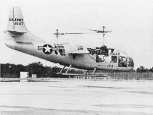
The Bell XV3, see Figure 1.13, of 1955 had a side-by-side rotor layout with each rotor having three blades. It was of the tilt rotor convertiplane configuration. It suffered from long shaft whirl mode instability. In 1958, it was redesigned to have two-bladed rotors with a short shaft.

The XV15 was rolled out in 1976 achieving its first flight in 1979. In 1980 it achieved a flight speed of 300 knots. This aircraft was the forerunner of the V22 which flew for the first time in 1989 and is in extensive use today.

The Kamov Ka22 of 1961 was developed in the Soviet Union and possessed a side-by-side layout. It was unusual in having forward-facing propellers at the wing tips.

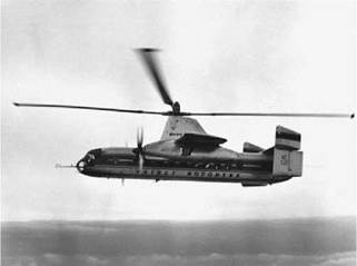
In November 1965 we find the Piasecki 16H-1 compound helicopter, see Figure 1.14, making its first flight and achieving 225 mph. This company is still active in the compound helicopter arena. The compound configuration has seen a number of efforts over the years. In the 1960s there was the Sikorsky S65 Blackhawk, a gunship based on the S61 rotor system but with a sleek fuselage shape and fitted with wings. Also in this period there was the Lockheed Cheyenne. Not only was it a compound helicopter with wings and an empennage of intermeshing tail rotor and pusher propeller, but also it had a main rotor controlled by a gyro placed above the main rotor head.

Figure 1.14 Piasecki 16H-1 (Courtesy Piasecki Aircraft Corp.)

We also now begin to see the emergence of extended mission lengths. In 1965, Gary Maher piloted a Hughes 300 to achieve the first solo crossing of the USA. It was a 10 day flight and required 33 refuelling stops. In 1967, a Sikorsky S61 was the first helicopter to achieve the notable goal of crossing the Atlantic Ocean. It took another 15 years (30 September 1982) before a Bell 206-1 became the first helicopter to achieve circumnavigation of the Earth. In July of the following year a Bell Jet Ranger was piloted to the first solo global circumnavigation.

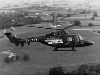
Speed has always been the touchstone of the rotary-wing aircraft and there are many attempts at achieving fast forward flight. Among many, in the UK the most notable of late happened on 11 August 1986. On this date, a Westland Lynx helicopter, flying over the Somerset Levels with Trevor Egginton at the controls, obtained the class world speed record of 400km/h – see Figure 1.15.

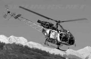
Figure 1.16 Alouette SA 315 Lama (Courtesy Steve Rod)

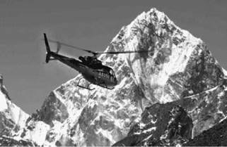
Figure 1.17 Eurocopter AS350 in the Himalaya (Courtesy Eurocopter)

The highest altitude was achieved by an Alouette SA315 Lama on 21 June 1972 when it flew to 40 820 ft – see Figure 1.16.

While this remains the altitude record it should not be forgotten that on 14 May 2005 a Eurocopter AS350 helicopter, piloted by Didier Delsalle, was the first to land on the summit of Mount Everest (see Figure 1.17), the highest point on Earth.

Just to prove the point, because of equipment difficulties, it did it again the following day!