Category Basics of Aero – thermodynamics

Transport of Mass

Governing Equations. Mass is a scalar entity. Mass transport is described by means of the (global) continuity equation (two-dimensional)

Подпись:, (V) , = 0

dt dx dy

The first term on the left-hand side represents the rate of increase of mass in the unit volume with time, the second and the third term the gain of mass by convective transport.

In the case of chemical non-equilibrium we have a “species” continuity equation for every involved species [2]15

dfH dp. jU dpi’v

dt dx dy


‘4/ ‘4/ .

dx dy


+ Smi


(4.84)


The terms in the bracket on the right-hand side represent the mass trans­port by diffusion, and Smi the source term of the species, Section 5 and Appendix A. The terms jix and jiy are the components of the mass-flux vector j. of the species i. This diffusive mass-flux is a flux relative to the con­vective (bulk-flow) mass flux pV_ [2]. Summation over all species continuity equations (4.84) results in the global continuity equation (4.83).

Hence we have the global and n species continuity equations, one more than needed. In praxis one can use the superfluous equation for an accuracy check.

The diffusion mass-flux vector, which we have mentioned already in the preceding Section 4.3.2, has four parts [2]

Подпись: —г —г(4.85)

For convenience we write these four parts in terms of a binary mixture with the species A and B:

— Mass diffusion due to a concentration gradient VcoA (Fick’s first law)

Подпись: (4.86)1{A = ~1{B = – pDabY^a-

Подпись: j(p) = _ j(p) J-A J-B Transport of Mass Подпись: (4.87)

— Mass diffusion due to a pressure gradient Ypa

— Mass diffusion due to a temperature gradient VTA (DJ is the thermo­diffusion coefficient)

lT = ~Ib] = -^Da^- (4-88)

— Mass diffusion due to body forces

£а=-£в – (4-89)

Of these four diffusion mechanisms the last two usually can be neglected in aerothermodynamics. Pressure-gradient diffusion may play a role in oblique shocks [21], curved nozzles, etc. In aerothermodynamic diffusion problems we deal with multi-component mixtures, hence we have to use generalized relations, given for instance in [2].

Transport of Mass Transport of Mass Подпись: Smi. Подпись: (4.90)

Finally we write eq. (4.84) in conservative form, and in terms of the mass fraction шр.

Подпись: (MA'U (MA'U oc PDAB (дшА/дх) PDAB (ША/L) Подпись: puCpL к Подпись: p puL pDAB P Подпись: Sc Re, (4.91)

Schmidt Number and Mass-Concentration Boundary-Layer Thick­ness. Noting that mass is a scalar entity we compare now, in the same way as we did for the energy flux, the convective and the molecular flux in x – direction, however only in terms of binary concentration-driven diffusion, eq. (4.86)

and find the Schmidt number

Подпись: Sc =pDab

This number is related to the Lewis number Le via the Prandtl number Pr

Подпись:L _ Dr _ рсрРлв _ Dab Sc к a

The following limiting cases of Sc can be distinguished:

— Sc ^ 0: the molecular transport of mass is much larger than the convective transport.

— Sc ^ to: the convective transport of mass is much larger than the molecular transport.

— Sc = O(1): the molecular transport of mass has the same order of magni­tude as the convective transport.

We compare now for Sc = O(1) the convective transport of mass in x- direction (мхи with the molecular transport of mass in у-direction jy, antic­ipating a mass-concentration boundary layer with the thickness 5M. We do this in the form given with eq. (4.84) after introducing the mass fractions xa and xb

Transport of Mass

Transport of Mass

д дшА

+ – a~(pDab—s— ду ду


(4.94)


Transport of Mass
Again we introduce in a schematic way characteristic data and find

Подпись:Подпись: (4.97)5м I Dab 1

L °V uL * y/ReLSc

Подпись: 5M 5 Подпись: 1 Подпись: (4.98)

and in terms of the boundary-layer running length x [39]

We can distinguish again three cases:

— Sc ^ 0: the mass-concentration boundary layer is much thicker than the flow boundary layer.

— Sc ^ to: the flow boundary layer is much thicker than the mass-concentra­tion boundary layer.

— Sc = O(1): the mass-concentration boundary layer has a thickness of the order of that of the flow boundary layer.

The above discussion has shown that mass transport can be described analogously to momentum and energy transport. However, the discussion is somewhat academic regarding thermo-chemical non-equilibrium flows, be­cause mass transport is not necessarily dominated by the surface boundary conditions (the thermal state of the surface), like in the case of the other entities. An exception possibly is the flow of a strongly dissociated gas past a fully catalytic surface.

Boundary Conditions. The global continuity equation, eq. (4.83), has first – order derivatives of the velocity components u, v, and the density p only. At the body surface the boundary conditions for u and v are those discussed for momentum transport in Sub-Section 4.3.1. For the density p, like for the pressure p, only a wall-compatibility equation, i. e., no boundary condition, can be prescribed at the body surface [4, 17]. Hence, if an explicit boundary condition is necessary for p, it must be described at the far-field or external boundary.

The situation is different with the species-continuity equations (4.84), (4.90). Here we have second-order derivatives with each of the diffusion­driving mechanisms. Regarding the boundary conditions at the body sur­face we note without detailed discussion four possible general cases (see also Section 5.6):

— equilibrium conditions for the species

= Ui(p, T )|ш ,

— vanishing mass-diffusion fluxes

jiy W 0,

— fully catalytic surface recombination

Шatomi lw °

— finite catalytic surface recombination (kw is the catalytic recombination rate at the wall)

Шi (kw i p, T) •

Regarding far-field or external boundary conditions the same holds for the continuity equations (global and species) as for the Navier-Stokes equations and the energy equation.

Transport of Energy

Governing Equations. Energy is a scalar entity. Energy transport is de­scribed by means of the energy equation. From the many possible formula­tions, see, e. g., [2], we choose for our initial considerations the conservative flux-vector formulation (we assume here also two-dimensional flow)[36]
The term on the left-hand side represents the rate of increase of energy in the unit volume with time, the term on the right-hand side the gain of energy.

The internal energy of our our model air—a mixture of thermally perfect gases—is defined by

Подпись:e (T, p) = cv (T, p) dT.

It is composed of the contributions of the molecular (im) and the atomic (ia) species

nm na

Подпись:Подпись: (4.54)

Подпись: d dt
Подпись: P(e + v2)
Подпись: Y-o

e ^ eim | ^ ^ &ia Є^а,

im = 1 ia = 1

which have the parts (see Section 5.2)

etranSim + erotim + evibr^m + eelim + AЄІ

and

eia = etransia + eelia + Aeia. (4.55)

etrans is the translation, erot the rotation, evibr the vibration, eel the electronic excitation, and A e the zero-point or formation energy [3].

V is the magnitude of the velocity vector

V = |V|. (4.56)

Подпись: V and </e the energy-flux vector Подпись: д d Є -1- Є ~хдх Уду’ Подпись: (4.57)

The symbol V in eq. (4.51) is the Nabla operator

q = р(є + l-V2)V +q + pV +т-V. (4.58)

—Є Z — —

The first term on the right-hand side of this relation represents the con­vective transport of energy into the unit volume, the second the molecular transport of energy, the third the work on the fluid by pressure forces (com­pression work), and the last by viscous forces (dissipation work).

The molecular transport of energy, q, in general, i. e., chemical non­equilibrium included, has two parts:

n

q = – kVT • (4.59)

І= 1

The first stands for the molecular transport of thermal energy (heat con­duction), and the second for the transport of thermal energy by mass diffusion due to chemical non-equilibrium of air as a mixture of thermally perfect gases. In eq. (4.59) hi is the enthalpy of the species i

hi = cPi dT, (4.60)

and j the diffusion mass flux.

—I

Transport of Energy

We find the heat transported towards the body surface, qgw, from the y-component of the energy-flux vector at the wall

Подпись: qgw Transport of Energy Подпись: w Подпись: du A «(— dy Подпись: w Подпись: (4.62)
Transport of Energy

If vw = 0, that is without suction or blowing at the wall, this equation reduces to

The first term is the classical heat-conduction term, the second the heat transport in chemical non-equilibrium flow, and the third finally a heat flux, which in the slip-flow regime appears in addition to the two other fluxes [21]. This third term of course disappears for non-slip flow.

Peclet Number, Prandtl Number, Lewis Number, Eckert Number, and Thermal Boundary-Layer Thickness. Noting that the energy flux is a scalar entity, we compare now—in the same way as we did it for the momentum flux—the convective and the molecular flux in x-direction.

To ease the discussion we introduce a simpler, and more familiar form of the energy equation in terms of the enthalpy h [2]

Подпись:dq. v _ d%_ dp dp

Подпись:dx dy dt dx dy

du dv du dv

rra—+TTO—+ гж,(—+ —)

By adding to the left-hand side of this equation the global continuity equation times the enthalpy we find, while expressing the mass-diffusion energy-transport term in eq. (4.59) for a binary gas, the conservative form of convective and molecular transport

Assuming perfect gas with h = cpT, and not anticipating a thermal bound­ary layer, we compare the convective and the conductive transport in x – direction (the first two terms in the first bracket on the left-hand side) after introduction of the simple proportionality дТ/дх ж T/L:

Подпись:

Transport of Energy
Подпись: +

pucpT pucpT pucpL ncp puL

—– — (Y ——– = —— = H P = ———- = НГ П P

k(dT /dx) k(T/L) к к p

Подпись: Pe Подпись: pucpL к Подпись: (4.66)

and find in this way the Peclet number:

and the Prandtl number:

Подпись: (4.67)Подпись:= P1 = pcp Re к ‘

The Prandtl number Pr can be written

Pr_ dh = Р/Р

k/pcp a

where

k

a=— (4.69)

pcp

is the thermal diffusivity [5], which is a property of the conducting material. The Prandtl number Pr hence is the ratio ‘kinematic viscosity v = p/p’ to ‘thermal diffusivity a’.

Of interest are the limiting cases of of the Peclet number Pe (compare with the limiting cases of the Reynolds number Re):

— Pe ^ 0: the molecular transport of heat is much larger than the convective transport.

— Pe ^ to : the convective transport of heat is much larger than the molecular transport.

— Pe = O(1): the molecular transport of heat has the same order of magni­tude as the convective transport.

Подпись: Le

which is interpreted as the ratio ‘heat transport by mass diffusion’ to ‘heat transport by conduction’ in a flow with chemical non-equilibrium. In the temperature and density/pressure range of interest in this book we have 0.5 < Le < 1.5 [8].

Transport of Energy Подпись: + ЕЛ + -) + dx Подпись: (4.72)

If we non-dimensionalize eq. (4.63) without the time derivative, and with proper reference data (p is non-dimensionalized with pu2), we find

All entities in this equation are dimensionless. The new parameter is the Eckert number

u2

E= —= (7-l)M2, (4.73)

CpT

with the Mach number defined by eq. (4.38). The Eckert number is interpreted as the ratio ‘kinetic energy’ to ‘thermal energy’ of the flow.

For E ^ 0, respectively M ^ 0, we find the incompressible case, in which of course a finite energy transport by both convection and conduction can happen, but where no compression work is done on the fluid, and also no dissi­pation work occurs. For E = 0 actually fluid mechanics and thermodynamics are decoupled.

We compare now for Pe = 0(1) the convective transport of heat in x- direction puCpT with the molecular transport of heat in у-direction qy, an­ticipating a thermal boundary layer with the thickness 5T. We do this in the differential form given with eq. (4.64)

Transport of Energy
Again we introduce in a schematic way characteristic data and find after rearrangement

Подпись:St k 1 1

— OC j ——— oc oc =

x Cppux Pex RexPr

Transport of Energy Подпись: (4.78)

The thickness of the thermal boundary layer St is related to the thickness of the flow boundary layer S = Sfiow by

— Pr ^ 0: the thermal boundary layer is much thicker than the flow boundary layer, which is typical for the flow of liquid metals.

— Pr ^ to: the flow boundary layer is much thicker than the thermal bound­ary layer, which is typical for liquids.

— Pr = O(1): the thermal boundary layer has a thickness of the order of that of the flow boundary layer. This is typical for gases, in our case air. However, since in the interesting temperature and density/pressure domain Pr < 1 [8], the thermal boundary layer is somewhat thicker than the flow boundary layer. This is also of importance for the wall-normal discretiza­tion of boundary-layer methods, see, e. g., [4].

Boundary Conditions. The energy equation, either in the form of eq. (4.51), or in the form of eq. (4.63), has terms of second order of the tem­perature T in both the x – and the y-direction. Hence we have to prescribe two boundary conditions. Like for momentum transport, one is defined at the body surface, the other for external flow problems (far-field or external boundary conditions) in principle at infinity away from the body. In addition we have to prescribe boundary conditions for the heat transport by mass diffusion in chemical non-equilibrium flow, and by velocity slip, eq. (4.62).

First we treat the ordinary heat-flux term. We have seen in Section 3.1 that five different situations regarding the thermal state at the body surface

are of practical interest. Before we look at the corresponding boundary con­ditions, we consider the general wall-boundary condition for T in both the continuum and the slip-flow regime, Section 2.3.

Подпись: T Transport of Energy Подпись: (4.79)

The general boundary condition for T at a body surface reads [20][37]

Here a is the thermal accommodation coefficient, which depends on the pairing gas/surface material : 0 ^ a ^ 1. Specular reflection, which means vanishing energy exchange, is given with a = 0, and diffusive reflection, indi­cating reflection accommodated to the surface temperature Tw with a = 1. Specular reflection hence indicates perfect decoupling of the temperature of the gas at the wall Tgw from the wall temperature Tw, i. e., a ^ 0: (dT/dy)w ^ 0. For air on any surface usually a = 1 is chosen.

Eq. (4.79) can be written in terms of the reference Knudsen number Knref

Transport of Energy Подпись: (4.80)

= Xref /Lref

— the classical wall boundary condition in the continuum-flow regime:

Knref < 0.01: Tgw = Tw, (4.81)

— and the temperature-jump condition in the slip-flow regime:

0.01 < Knref < 0.1 : Tgw = Tw. (4.82)

Again the reference Knudsen number must be chosen according to the flow under consideration, e. g., for boundary-layer flow it would be based on the boundary-layer thickness. And also here it should be remembered that there are no sharp boundaries between the two flow regimes.

With regard to the boundary conditions, which represent the five different situations of the thermal state of the surface (Section 3.1), we consider only the continuum-flow regime case with Tw = Tgw and find:[38]

1. Radiation-adiabatic wall: qgw = qraci —>• кЩ-ш = eaT4.

2. Wall temperature at the wall without radiation cooling: Tw.

3. Adiabatic wall: qgw = 0 —>• = 0.

4. Wall temperature at the wall with radiation cooling: Tw, and qrad =

eaTw.

5. Wall heat flux (into/out of the wall material) is prescribed: qw = qgw –

qrad.

There remains to consider the energy transport by mass diffusion in chem­ical non-equilibrium flow. The wall-boundary conditions of the diffusion flux jiy will be treated in the following Sub-Section 4.3.3. Important are the cases of finite and full catalytic recombination of atoms at the surface, Section 5.6. Catalytic recombination enhances strongly the heat transport towards the surface. On the one hand this is due to the release of dissociation energy in the recombination process. On the other hand, since the atomic species disappear partly or fully at the surface, the mass-diffusion flux as such is enlarged.

Finally the velocity-slip term in eq. (4.62) is recalled. The corresponding boundary conditions are found in Sub-Section 4.3.1.

Regarding external boundary conditions the same holds for the energy equation as for the Navier-Stokes equations. Special situations exist for in­ternal flows, e. g., in inlets, diffuser ducts etc., which we do not discuss here.

Equations of Motion, Initial Conditions, Boundary Conditions, and Similarity Parameters

4.3.1 Transport of Momentum

Governing Equations. Momentum transport is described by means of the Navier-Stokes equations. Consider, for two-dimensional flow, the equation for momentum transport in ж-direction

Подпись: дт дт у IXX diff u‘yxdiff дх ду
Подпись: du du du <’i)t + 'шні + '••%
Подпись: <>!' (дтхх дтух дх у дх ду

(4.27)

The first term on the left-hand side represents the rate of increase of momentum in the unit volume with time, the second and third the gain of momentum by convective transport. On the right-hand side the first term stands for the pressure force on the unit volume, the first bracket for the gain of momentum by molecular transport, and the second bracket for the gain of momentum by mass diffusion. This term usually can be neglected.

(4.28)

The components of the viscous stress tensor r in eqs. (4.27) and (4.28) are for a compressible Newtonian fluid7

Equations of Motion, Initial Conditions, Boundary Conditions, and Similarity Parameters Equations of Motion, Initial Conditions, Boundary Conditions, and Similarity Parameters

The equation for the momentum transport in у-direction reads similarly, with the terms having the same meaning as before

dv 2 du dv

T»» = -2% + <3“-K) {&;+ fy) – (4 31)

Here we meet another transport property, the bulk viscosity к. It is con­nected to rotational non-equilibrium of polyatomic gases [3]. For practical purposes the formulation of this connection for air and its molecular con­stituents can be found in, e. g., [16]. For low-density monatomic gases к — 0. For the flow problems considered here we can assume in general к ^ p, and therefore neglect it.

7 Note that these components often are defined with opposite sign, e. g., Txx =

~ (§d – K)(fy + If)’ see’ e-g- M-

Подпись: u Подпись: dp dpu dpv dt dx dy Подпись: 0, Подпись: (4.32)

By adding to eq. (4.27) the “global” continuity equation multiplied by u, Sub-Section 4.3.3

we find the conservative formulation for the momentum transport in x – direction, see also Appendix A[32]

d(pu) d, 2 d, . .

+ -7^; {pu~ +p + txx) + — (pvu + тху) = 0. (4.33)

(pv2 + p + Tyy)

Equations of Motion, Initial Conditions, Boundary Conditions, and Similarity Parameters Подпись: d_ dy Подпись: 0. Подпись: (4.34)

The conservative formulation for the momentum transport in y-direction is found likewise:

Подпись: Tw Подпись: ■Tyx w Подпись: du dv dy dx Подпись: w Подпись: (4.35)

The shear stress exerted on the body surface, i. e., the transport of x- momentum in (negative) y-direction towards the surface, is found from eq. (4.30)

Подпись: Tw Equations of Motion, Initial Conditions, Boundary Conditions, and Similarity Parameters Подпись: (4.36)

If distributed blowing or suction with a gradient in x-direction is not present, we arrive with dv/dxw = 0 at the classical wall-shear stress relation

For the surface pressure, which is a force normal to the surface, we do not have a relation, since it is an implicit result of the solution of the governing equations [17].

Mach Number, Reynolds Number, and Flow Boundary-Layer Thickness. We begin by comparing the convective x-momentum flux term and the pressure term in eq. (4.33):

Подпись:Подпись: (4.37)22 pu pu

p pRT

Подпись: M with a being the speed of sound Подпись: u , a Подпись: (4.38)

The Mach number M is defined by

The magnitude of the Mach number governs compressibility effects in fluid flow, Chapter 6. Here we employ it only in order to distinguish flow types:

— M = 0: incompressible flow.

— M ^ Mcrit, lower: subsonic flow.[33] [34]

MCrit, lower ~ M ~ Mcrit, upper : transonic flow.

— Mcrit, upper ^ M ^ 5: supersonic flow.

— M ^ 5: hypersonic flow.

Hypersonic flow usually is defined as flow at speeds larger than those at which first appreciable high-temperature real-gay effects occur: M « 5. K. Oswatitsch defines hypersonic flow with M [18], see also Section 6.8. In

practice this means a Mach number large enough so that the Mach number independence principle holds.

Noting that the momentum flux is a vector entity, we compare now in a very schematic way the convective and the molecular ж-momentum flux in ж-direction in the first large bracket of eq. (4.33) after introducing the simple proportionality тхх ж p(u/L), which here does not anticipate the presence of a boundary layer

Подпись:pu2 pu2 puL

— * ~пт = — = Де>

тхх ft(u/L) ft

and find in this way the Reynolds number Re. It can be interpreted as the ratio ‘convective transport of momentum’ to ‘molecular transport of momen­tum’ [4]. The Reynolds number is the principle similarity parameter governing viscous phenomena, Chapter 7.

The following limiting cases of Re can be distinguished:

— Re ^ 0: the molecular transport of momentum is much larger than the convective transport, the flow is the “creeping” or Stokes flow (see, e. g., [2, 19]): the convective transport can be neglected.

— Re ^ to: the convective transport of momentum is much larger than the molecular transport, the flow can be considered as inviscid, i. e., molecular transport can be neglected. The governing equations are the Euler equa­tions, i. e., in two dimensions eqs. (4.27) and (4.28) without the molecular
and mass-diffusion transport terms. If the flow is also irrotational, they can be reduced to the potential equation [6].

— Re = O(1): the molecular transport of momentum has the same order of magnitude as the convective transport, the flow is viscous, i. e., it is boundary-layer, or in general, shear-layer flow.[35]

We refrain from a discussion of the general meaning of the Reynolds number as a similarity parameter. This can be found in text books on fluid mechanics.

Equations of Motion, Initial Conditions, Boundary Conditions, and Similarity Parameters

For Re = O(1) the convective transport of ж-momentum in x-direction pu? is compared now with the molecular transport of ж-momentum in y-direction Txy, anticipating a boundary layer with the (asymptotic) thickness S. We do this in the differential form given with eq. (4.27), assuming steady flow, and neglecting the second term of Tyx in Eq.(4.30)

Подпись:Подпись: (4.43)u [ли

pu-oc

After rearrangement we obtain for the boundary-layer thickness S

S I p 1

— OC 4 ——– OC. ,

L у puL fReL

Подпись: S — oc ж Подпись: p 1 pux /Rex Подпись: (4.44)

and, using the boundary-layer running length ж as characteristic length

This boundary-layer thickness is the thickness of the flow or ordinary boundary layer S = Sflow [19]. We will identify below with the same kind of consideration the thicknesses of the thermal, as well as the diffusion boundary layer, which are different from the flow boundary-layer thickness. The prob­lem of defining actual boundary-layer thicknesses is treated in Sub-Section 7.2.1.

Boundary Conditions. The Navier-Stokes equations (4.27) and (4.28) have derivatives of second order of the velocity components u and v in both ж – and y-direction. Hence we have to prescribe two boundary conditions for each velocity component. One pair (in two dimensions) of the boundary conditions is defined at the body surface, the other for external flow problems (far – field or external boundary conditions), in principle, at infinity away from the

body. For internal flows, e. g., inlet flows, diffuser-duct flows, etc., boundary conditions are to be formulated in an appropriate way.

We treat first the wall-boundary conditions for u and v, and consider the situation in both the continuum and the slip-flow regime, Section 2.3.

Подпись: uw Equations of Motion, Initial Conditions, Boundary Conditions, and Similarity Parameters Подпись: (4.45)

For the tangential flow component uw at a body surface we get [20]

Here a is the reflection coefficient, which is depending on the pairing gas/surface material : 0 A a A 1. Specular reflection is given with a = 0, and diffusive reflection with a =1. Specular reflection indicates perfect slip, i. e., a ^ 0: (du/dy)w ^ 0. For air on any surface usually a = 1 is chosen. In Section 9.4 we will show results of a study on varying reflection coefficients.

The second term in the above equation

3 p dT

4 Подпись: wpT dx

in general is not taken into account in aerothermodynamic computation mo­dels. It induces at the wall a flow in direction of increasing temperature. On radiation-cooled surfaces with the initially steep decrease of the radiation – adiabatic temperature in main flow direction it would reduce the magnitude of slip flow. No results are available in this regard. However, the term can be of importance for measurement devices for both hypersonic hot ground – simulation facilities and flight measurements in the slip-flow regime.

Equations of Motion, Initial Conditions, Boundary Conditions, and Similarity Parameters Подпись: (4.46)

After the mean free path, eq. (2.15), has been introduced into the se­cond term on the right-hand side, and after rearrangement, eq. (4.45) can be written in terms of the reference Knudsen number Knref = Xref /Lref

We find now in accordance with Section 2.3:

— the classical no-slip boundary condition for the continuum-flow regime:

Knref < 0.01 : uw =0, (4.47)

— and the slip-boundary condition eq. (4.45) for the slip-flow regime:

0.01 < Knref < 0.1 : uw > 0. (4.48)

The reference Knudsen number Knref must be chosen according to the flow under consideration. For boundary-layer flow, for example, the length scale Lref would be the boundary-layer thickness 5. Further it should be remembered that there are no sharp boundaries between the continuum and the slip-flow flow regime, Section 2.3.

The boundary condition for the normal flow component v at the body surface usually is

vw = 0. (4.49)

If there is suction or blowing through the surface, of course we get

vw =0 (4.50)

according to the case under consideration. Whether the suction or blowing orifices can be considered as continuously distributed or discrete orifices must be taken into account. For blowing through the surface also total pressure and enthalpy of the fluid, as well as its composition must be prescribed.

Far-field or external boundary conditions must, as initially mentioned, in principle be prescribed at infinity away from the body surface, also in down­stream direction. In reality a sufficiently large distance from the body is cho­sen. Because a flight vehicle induces velocity overshoots and velocity/total pressure defects in its vicinity and especially in the wake (due to lift, induced and viscous drag), far-field boundary conditions must ensure a passage of the flow out of the computation domain without upstream damping and reflec­tions. For this reason special formulations of the far-field boundary conditions are introduced, especially for subsonic and transonic flow computation cases.

In supersonic and hypersonic flows, depending on the employed compu­tation scheme, the upstream external boundary conditions can be prescribed just ahead of the bow shock if bow-shock capturing is used, or at the bow shock (via the Rankine-Hugoniot conditions, Section 6.1), if bow-shock fitting is employed. Then downstream of the body appropriate far-field boundary conditions must be given, as mentioned above.

The situation is different with two-domain computation methods, like coupled Euler/boundary-layer methods. Then external boundary conditions, found with solutions of the Euler equations, are applied at the outer edge of the boundary layer [4].

Computation Models

The relations for the determination of the transport properties viscosity p and thermal conductivity k, which we have considered in the preceding sub­sections, are valid in the lower temperature domain, i. e., as long as dissocia­tion does not occur. Air begins to dissociate at temperatures between 1,500 K and 2,000 K, depending on the density level. In general the following holds: the lower the density, the lower is the temperature at which dissociation occurs.

If appreciable dissociation is present, the transport properties are de­termined separately for each involved species. Mixing formulas (exact, and approximate ones such as Wilke’s and other [2, 3]) are then employed in order to determine the transport properties of dissociated air.

Computation Models Подпись: (4.25)

Wilke’s semi-empirical formula, for example, reads [2]:

Computation Models Подпись: -0.5 Подпись: Mi Computation Models Подпись: (4.26)

with

where pi, xi and Mi are viscosity, mole fraction and molecular weight of the species i, respectively, and j is a dummy subscript.

Wilke’s formula is used in aerothermodynamics with good results, also for the determination of the thermal conductivity of gas mixtures. For multi­component diffusion coefficients the available mixing formulae, [2], are less satisfactory [9].

The transport properties of gas mixtures in thermo-chemical equilibrium are always functions of two thermodynamic variables, for example internal energy e and density p.

The nowadays fully accepted theoretical base for the determination of transport properties is the Chapman-Enskog theory for gases at “low” density with extensions also for dissociated air in equilibrium or in non-equilibrium. In the methods of numerical aerothermodynamics curve-fitted state surfaces are employed, see, e. g., [10], in order to obtain in a fast and exact manner the needed data. They use extensive data bases, e. g., [11]—[13].

In general it is accepted that transport properties of multi-species air at the flow conditions considered here can be determined to a sufficient degree of accuracy [9, 14]. The situation is different with flow problems exhibiting very high temperatures, and with combustion and combustion-wake problems of hypersonic flight propulsion systems.

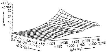
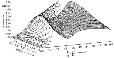
Examples of curve-fitted state surfaces of viscosity p(p, e) and thermal conductivity k(p, p/p) [10] for the typical pressure/density/internal energy range encountered by the flight vehicle classes in the background of this book are shown in Figs. 4.6 and 4.7.[31]

Computation Models

Fig. 4.6. Viscosity p of air as function of the density p and the internal energy e [10]. Database: [11] (p0 = 1.243 kg/m3, eo = 78,408.4 m2/s2).

Computation Models

Fig. 4.7. Thermal conductivity k of air as function of the density p and the ratio pressure/density p/p [10]. Database: [11] (p0 = 1.292 kg/m3, p0 = 1.0133-106 Pa).

Mass Diffusivity

The Chapman-Enskog theory gives for the mass diffusivity of a binary gas a relation similar to those for the viscosity and the thermal conductivity:

Mass Diffusivity

Fig. 4.4. Thermal conductivity k, different approximations, Table 4.4, as function of the temperature T.

Mass Diffusivity

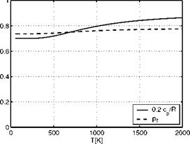
Fig. 4.5. Prandtl number Pr and specific heat at constant pressure cp of air, Table 4.4, as function of the temperature T.

VT3 (ma + Mb)

Dab = DBa = const.—————- P— ————- . (4.24)

pazA B QDab

The dimension of DaB is [m2/s]. Since we do not intend to derive and use approximate relations for it, we renounce a detailed discussion and refer the reader to, e. g., [2, 3].

Thermal Conductivity

The thermal conductivity of pure monatomic gases can be determined in the frame of the Chapman-Enskog theory [2]

к = 8.3225 -1(Г2у/^М. (4.16)

azl2k

Подпись: к Подпись: 15 До Тмм' Подпись: (4.17)

The dimension of к is [W/mK]. The dimensionless collision integral Qk is identical with that for the viscosity QM. With this identity it can be shown for monatomic gases:

The Chapman-Enskog theory gives no relation similar to eq. (4.16) for polyatomic gases. An approximate relation, which takes into account the exchanges of rotational as well as vibration energy of polyatomic gases, is the semi-empirical Eucken formula, where cp is the specific heat at constant pressure

к={Ср + ш)^ (4Л8)

The monatomic case is included, if for the specific heat cp = 2.5 R0/M is taken.

From eq. (4.18) the relation for the Prandtl number Pr can be derived:

Pr =f^ =____________ (4 19)

к cp + 1.25Д0/М 9y — 5′ V ;

This is a good approximation for both monatomic and polyatomic gases [3]. у is the ratio of the specific heats: у = cp/cv.

For temperatures up to 1,500 K to 2,000 K, an approximate relation due to C. F. Hansen—similar to Sutherland’s equation for the viscosity of air—can be used [8]

T 1.5

kHan = 1-993 • 10-3—————- . (4.20)

T+112.0 v ;

A simple power-law approximation can also be formulated for the ther­mal conductivity: к = ckTШк. For the temperature range T ^ 200 K the approximation reads—with the constant ck1 computed at T = 100 K—

к1 = ck1 TUkl = 9.572 • 10-5 T, (4.21)

and for T ^ 200 K—with the constant ck2 computed at T = 300 K—

k2 = ck2TUk2 = 34.957 • 10-5 T0-75. (4.22)

Подпись: cp Подпись: 3.5R + cv. Thermal Conductivity Подпись: (4.23)

In Table 4.4 and Fig. 4.4 we compare the results of the four above relations in the temperature range up to T = 2,000 K, again with the understanding, that a more detailed consideration might be necessary due to possible disso­ciation above T « 1,500 K. The data computed with eq. (4.18) were obtained for non-dissociated air with vibration excitation from

For the determination of the specific heats at constant volume cVvibr see Section 5.2. The mass fractions wO2 = 0.26216, and uN2 = 0.73784 were taken from Sub-Section 2.2 for air in the low-temperature range.

Table 4.4. Comparison of thermal-conductivity data к [W/mK] computed with eqs. (4.18) to (4.22) for some temperatures T [K] of air (see also Fig. 4.4). Included are the specific heat at constant pressure cp (second column), and the Prandtl number Pr based on eq. (4.19) (last column).

T

c-p/R

к TO2 eq.(4.18)

к Han TO2

О

i—1

fe2 – to2

Pr

50

3.500

0.476

0.435

0.478

0.7368

75

3.500

0.715

0.692

0.717

0.7368

too

3.500

0.957

0.940

0.957

1.100

0.7368

200

3.500

1.820

1.807

1.914

1.859

0.7368

300

3.508

2.521

2.514

2.872

2.519

0.7373

400

3.538

3.131

3.114

3.833

3.126

0.7389

600

3.667

4.256

4.114

4.238

0.7458

800

3.830

5.329

4.945

5.258

0.7539

1,000

3.974

6.335

5.668

6.216

0.7607

1,500

4.204

8.535

7.183

8.425

0.7708

2,000

4.242

10.453

8.440

10.454

0.7724

The table shows that the data from the Hansen relation compare well with the Eucken data except for the temperatures above approximately 600 K, where they are noticeably smaller. The power-law relation for T ^ 200 K fails for T ^ 200 K. The second power-law relation gives good data for T ^ 200 K.

It should be noted, that non-negligible vibration excitation sets in already around T = 400 K. This is reflected in the behavior of the Prandtl number, Fig. 4.5, where also cp/R is given. To obtain, as it is often done, the thermal conductivity simply from eq. (4.19) with a constant Prandtl number would introduce errors above T « 400 K. The Prandtl number of air generally is Pr < 1 in a large temperature and pressure range [8].[30]

Viscosity

The viscosity of pure monatomic, but also of polyatomic gases, in this case air, can be determined in the frame of the Chapman-Enskog theory with [2]

RyjMT

p = 2.6693 • 10~6-Ц,—– . (4.12)

a2Q^

The dimensions and the constants for air in the low temperature do­main, [2], are: viscosity p [kg/ms], molecular weight M = 28.9644 kg/kmole, Temperature T [K], collision diameter (first Lennard-Jones parameter) a = 3.617-10-10 m. The dimensionless collision integral, [2], is a function of the quotient of the temperature and the second Lennard-Jones parameter e/k = 97 K, Appendix B.1.

An often used relation for the determination of the viscosity of air is the Sutherland equation

6 TLS

AtStttft= 1.458-10-6r+ii04. (4.13)

A simple power-law approximation is p = c^T. In [7] different values of are proposed for different temperature ranges. We find here for the temperature range T ^ 200 K the approximation—with the constant c^1 computed at T = 97 K—

p1 = c^Tu^ = 0.702 • 10-7T, (4.14)

and for T ^ 200 K—with the constant cM2 computed at T = 407.4 K—

p2 = c^2Tu^2 = 0.04644 • 10-5T°’65. (4.15)

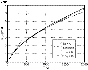
In Table 4.3 and Fig. 4.3 we compare results of the four above relations in the temperature range up to T = 2,000 K, with the understanding, that a more detailed consideration might be necessary due to possible dissociation above T « 1,500 K. The data computed with eq. (4.12) were obtained by linear interpolation of the tabulated collision integral [2], Appendix B.1.

The table shows that the data from the Sutherland relation compare well with the exact data of eq. (4.12) except for the large temperatures, where they are noticeable smaller. The power-law relation for T ^ 200 K fails above T = 200 K. The second power-law relation gives good data for T A 300 K. For T = 200 K the error is less than nine per cent. At large temperatures the exact data are better approximated by this relation than by the Sutherland relation.

T

H -105 eq. (4.12)

f-LSuth ’10

£

I—1

О

ОТ

P’2 TO5

50

0.349

0.321

0.351

75

0.525

0.511

0.526

100

0.702

0.693

0.702

0.927

200

1.335

1.328

1.402

1.454

300

1.846

1.846

2.106

1.892

400

2.279

2.285

2.808

2.281

600

3.016

3.016

2.969

800

3.655

3.623

3.580

1,000

4.226

4.152

4.139

1,500

5.453

5.260

5.387

2,000

6.632

6.179

6.495

Table 4.3. Comparison of viscosity data p [kg/ms] of air computed with eqs. (4.12) to (4.15) for some temperatures T [K] (see also Fig. 4.3).

Подпись: x 10-5

Fig. 4.3. Viscosity p of air, different approximations, Table 4.3, as function of the temperature T.

Transport Properties

4.2.1 Introduction

The molecular transport of the three entities momentum, energy, and mass basically obeys similar laws, which combine linearly the gradients of flow velocity, temperature and species concentration with the coefficients of the respective transport properties: viscosity, thermal conductivity, diffusivity, see, e. g., [2]. Fluids, which can be described in this way are called “Newtonian fluids”.

The basic formulation for molecular momentum transport is Newton’s law of friction

Подпись: du Tyx = ;v (4.9)

Here Tyx is the shear stress exerted on a fluid surface in x-direction by the y-gradient of the velocity u in that direction. The coefficient p is the fluid viscosity.

Подпись: Чу Подпись: , dT dy ' Подпись: (4.10)

Similarly, Fourier’s law of heat conduction reads:

The heat flux in the y-direction, qy, is proportional to the temperature gradient in that direction. The coefficient к is the thermal conductivity. If thermo-chemical non-equilibrium effects are present in the flow, heat is trans­ported also by mass diffusion, Section 4.3.2. Note that always the transport is in the negative y-direction.

This also holds for the molecular transport of mass, which is described by Fick’s first law

jAy = —jBy = – pDAB^j~. (4.11)

The diffusion mass flux jAy is the flux of the species A in y-direction relative to the bulk velocity v in this direction. It is proportional to the mass-fraction gradient d^A/dy in that direction. Dab = DBa is the mass diffusivity in a binary system with the species A and B. The reader is referred to, e. g., [2] for equivalent forms of Fick’s first law. Besides the concentration- driven diffusion also pressure-, and temperature-gradient driven diffusion can occur, Sub-Section 4.3.3. Molecular transport of mass occurs in flows with thermo-chemical non-equilibrium, but also in flows with mixing processes, for instance in propulsion devices.

The transport properties viscosity p, thermal conductivity к, and mass diffusivity DaB of a gas are basically functions only of the temperature. We give in the following sub-sections relations of different degree of accuracy for the determination of transport properties of air. Emphasis is put on simple power-law approximations for the viscosity and for the thermal conductivity. They can be used for quick estimates, and are also used for the basic analytical
considerations throughout the book. Of course they are valid only below approximately T = 2,000 K, i. e., for not or only weakly dissociated air. Models of high-temperature transport properties are considered in Sub-Section 4.2.5.

Transport Phenomena

In order to ease the discussion we consider in general steady compressible and two-dimensional flow in Cartesian coordinates. The nomenclature is given in Fig. 4.1. The coordinate x is the stream-wise coordinate, tangential to the surface. The coordinate y is normal to the surface. The components of the velocity vector V in these two directions are и and v, the magnitude of the speed is V = V_ = /u[26] [27] + v2.1

Подпись: VПодпись:Transport Phenomenav

u

x

The governing equations of fluid flow will be discussed as differential equa­tions in the classical formulation per unit volume, see, e. g., [1, 2]. The fluid is assumed to be a mixture of thermally perfect gases, Chapter 2. However, for the discussion we usually consider it only as a binary mixture with the two species A and B.

Fluid flow transports the three entities

— momentum (vector entity),

— energy (scalar entity),

— mass (scalar entity).

The transport mechanisms of interest in this book are

1. convective transport,

2. molecular transport,2

3. turbulent transport,

4. radiative transport.[28]

For a detailed discussion the reader is referred to the literature, for in­stance [2].

Under “convective” transport we understand the transport of the entity under consideration by the bulk motion of the fluid. In steady flow this hap­pens along streamlines (in unsteady flow we have individual fluid particle
“path lines”, and also “streak lines”, which represent the current locus of particles, which have passed previously through a fixed point). Under which circumstances a flow can be considered as steady will be discussed at the end of this section. If convective transport is the dominant transport mechanism in a flow, we call it “inviscid” flow.

“Molecular” transport happens by molecular motion relative to the bulk motion. It is caused by non-uniformities, i. e., gradients, in the flow field [3]. The phenomena of interest for us are viscosity, heat conduction, and mass diffusion, Table 4.1.

Table 4.1. Molecular transport phenomena.

Phenomenon

Molecular transport of

Macroscopic cause

Viscosity

momentum

non-uniform flow velocity

Heat conduction

energy

non-uniform temperature

Diffusion

mass

non-uniform concentration of species, pressure and temperature gradients

Molecular transport occurs in all directions of the flow field. Dominant directions can be present, for instance in boundary layers or, generally, in shear layers.

If molecular transport plays a dominant role in a flow field, we call the flow summarily “viscous flow” .[29] In fact, as we also will see later, all fluid flow is viscous flow. It is a matter of dominance of the different transport mechanisms, whether we speak about inviscid or viscous flow.

“Turbulent” transport is an apparent transport due to the fluctuations in turbulent flow. In fluid mechanics we treat turbulent transport of momentum, energy and mass usually in full analogy to the molecular transport of these entities, however with apparent turbulent transport properties, see, e. g., [4]. In general the “effective” transport of an entity Фef f is defined by adding the laminar (molecular) and the turbulent (apparent) part of it:

Фeff = Ф1ат + ФЫтЬ – (4.1)

“Radiative” transport in the frame of this book is solely the transport of heat away from the surface for the purpose of radiation cooling (Chapter 3). In principle it occurs in all directions and includes emission and absorption processes in the gas, see, e. g., [2, 3, 5], which, however, are neglected in our considerations.

In Table 4.2 we summarize the above discussion.

Item

Momentum

Energy

Mass

Convective transport

X

X

X

Molecular transport

X

X

X

Turbulent transport

X

X

X

Radiative transport

X

Table 4.2. Schematic presentation of transport phenomena.

Подпись: D Dt Подпись: д д д d » + “& +’’зї + ”3V Подпись: (4.2)

The three entities considered here, loosely called the flow properties, change in a flow field in space and in time. This is expressed in general by the substantial time derivative, also called convective derivative [2, 6]

This is the derivative, which follows the motion of the fluid, i. e., an ob­server of the flow would simply float with the fluid.

We note in this context that the aerothermodynamic flow problems we are dealing with in general are Galilean invariant [1]. Therefore we can con­sider a flight vehicle in our mathematical models and in ground simulation (computational simulation, ground-facility simulation) in a fixed frame with the air-stream flowing past it. In reality the vehicle flies through the—quasi­uniform—atmosphere.

The first term on the right-hand side, д/dt, is the derivative with respect to time, the partial time derivative, which describes the change of an entity in time at a fixed locus x, y, z in the flow field.

Подпись: d dt Transport Phenomena Подпись: (4.3)

The substantial time derivative D/Dt itself is a specialization of the total time derivative d/dt

where the observer moves with arbitrary velocity with the Cartesian velocity components dx/dt, dy/dt, and dz/dt.

In our applications we speak about steady, quasi-steady, and unsteady flow problems. The measure for the distinction of these three flow modes is the Strouhal number Sr. We find it by means of a normalization with proper reference values, and hence a non-dimensionalization, of the constituents q of the substantial time derivative eq. (4.2)

q = qref q*■ (4.4)

Here q = t, u, v, w, x, y, z, while qref are the respective normalization parameters. q and qref have the same dimension, whereas q* are the corres­ponding non-dimensional parameters, which are of the order one.

If the residence time is small compared to the reference time, in which a change of flow parameters happens, we consider the flow as quasi-steady, because Sr ^ 0. Steady flow is characterized by Sr = 0, i. e., it takes infinitely long for the flow to change in time (tref ^ж).

Unsteady flow is present if Sr = 0(1). For practical purposes the assump­tion of quasi-steady flow, and hence the treatment as steady flow, is permitted for S’r ^ 0.2, that is, if the residence time tres is at least five times shorter than the reference time tref. This means that a fluid particle “travels” in the reference time tref five times past the body with the reference length Lref.

Again we must be careful with our considerations. For example, the move­ment of a flight vehicle may be permitted to be considered as at least quasi­steady, Section 1.5, while at the same time truly unsteady movements of a control surface may occur. In addition there might be configuration details, where highly unsteady vortex shedding is present.

The flows treated in this book are considered to be steady flows. In the following sections, however, we present and discuss sometimes the governing equations also in the general formulation for unsteady flows.

Transport of Momentum, Energy, and Mass

Fluid flow is characterized by transport of mass, momentum and energy. In this chapter we treat the transport of these three entities and its mathe­matical description in a basic way. Similarity parameters and, in particular, surface boundary conditions will be discussed in detail.

Similarity parameters enable us to distinguish and choose between phe­nomenological models and the respective mathematical models. The Knudsen number, which we met in Chapter 2.3, is an example. It is used in order to distinguish flow regimes. As we will see, for the transport of the three entities different phenomenological models exist, which we characterize with the aid of appropriate similarity parameters.

Surface boundary conditions receive special attention because they gov­ern, together with the free-stream conditions and the flight-vehicle geometry, the flow and thermo-chemical phenomena in the flow-regime of interest. In addition, they govern aerodynamic forces and moments as well as mechanical and thermal loads on the flight vehicle.

After a general introduction, which also shows how to distinguish between steady and unsteady flows, we look briefly at the transport properties of air. Then we treat in detail the continuum-regime equations of motion—for con­venience, although with some exceptions, in two dimensions and Cartesian coordinates (the formulations of the governing equations in general coordi­nates are given in Appendix A)—, as well as the similarity parameters, and surface boundary conditions. We treat first momentum transport, because here the boundary-layer concept plays the major role. The transport of the two other entities is treated in an analogous way.

Far-field or external boundary conditions as well as initial conditions are in general not considered in detail in this book. In a flight situation these are the free-stream conditions. With internal flows, also wind-tunnel flows, as well as with special phenomenological models like the boundary-layer, however special considerations become necessary. They will be discussed in the respective sections.

(C Springer International Publishing Switzerland 2015 E. H. Hirschel, Basics of Aerothermodynamics,

DOI: 10.1007/978-3-319-14373-6 _4