Category Canonical impulse solutions

Natural response

For the fixed-stick case of no control inputs, A 8 = 0, the general solution of the Linear Time Invariant (LTI) ODE system (9.35) is a superposition of eight flight-dynamics eigenmodes,

8

Ax(t) = ^2 Vk exp(Afct) , Afc = at + i Wfc (9.36)

k=l

where A1…8 are the nonzero eigenvalues and vl…8 are the corresponding eigenvectors of the Jacobian matrix A. Each of the remaining four zero eigenvalues corresponds to a shift in x, y, z, ф, which has no influence on the dynamics and hence is excluded from the mode summation.

The magnitude of each wt and the sign and magnitude of at indicate the nature of that mode. If wt = 0 then the motion is monotonic, and if wt = 0 then the motion is oscillatory. The latter actually consists of two complex-pair modes, A = a ± i w. If at > 0 then that mode is unstable, meaning that the aircraft will exhibit exponential divergence from the trimmed flight state.

9.8.3 Symmetry

In the completely general case, the A and B matrices of the linearized dynamics system (9.35) are nearly full. But if we have

• geometric symmetry (the airplane is left/right symmetric), and

• aerodynamic symmetry with v0 = p0 = r0 = ф0 = 0, and

• negligible onboard angular momentum, h ~ 0,

then A and 13 have the following form after the state vector and the equations are re-ordered as indicated. Zero or nearly zero matrix elements are shown blank.

Подпись: (Подпись: (9.37)/

Au

AW A q aO

Подпись: d_ dt AV A p

}

Ar

А ф Axe A Vе A ze A^

T J

The first four rows constitute the Longitudinal Dynamics subset, the middle four rows are the Lateral Dy­namics subset, and the last four rows are the Navigation subset.

The last four navigation variables Axe, Aye, Aze, Aф generally have zero matrix columns, even for asym­metric aircraft. This implies that the matrix will have at least four zero eigenvalues, Аддо,11,12 = 0, whose corresponding eigenmodes contain only the steady displacements of the four navigation variables.

Подпись:Vg exp(0t) = { V10 exp(0t) = { V11 exp(0t) = {

V12 exp(0t) = {

This is expected from coordinate invariance – the dynamics cannot be affected if the airplane position is displaced, or if it is pointed in another direction in the plane parallel to the Earth surface. This justifies excluding these four trivial steady displacement modes from the dynamical mode summation (9.36).

One notable exception occurs if atmospheric property variation is significant over the vertical extent of the motion. In this case there will be some dependence on the Aze variable, and there will be only three trivial modes present in the system.

[1] If only one type of singularity is present (e. g. only vorticity but no source density), and if in addition the overall lumped vortex strength Г is nonzero, then the far-field doublets can be made to vanish by a suitable choice of the vortex location, which is then defined as the vorticity centroid. In the case of the thin airfoil, this location is also the center of lift, defined as the point about which the pitching moment is zero.

[2] For favorable pressure gradients a> 0, the velocity profile is “full” near the wall, with a monotonic curvature, relatively large skin friction coefficient Cf values, and small shape parameter H values.

• For adverse pressure gradients a< 0, the velocity profile is inflected, with a smaller skin friction and large shape parameters H.

• There is a minimum value a ~ -0.0904, which is the incipient-separation case, with Cf =0 and H ~ 4.029 . For a less than this minimum, no physical self-similar solution of the boundary layer equations (4.21) exists.

• Separated-flow solutions with Cf < 0 and H > 4.029 do exist, but their a parameter is less negative than the minimum value. They also exhibit reversed flow U < 0 near the wall.

[3] Forced transition.

This is caused by a geometric feature on the surface, such as a panel edge, rivet line, or an intentionally – placed “trip strip.” If the feature’s size is comparable to the height of the local boundary layer, as mea­sured by the displacement thickness for example, then it is a strong receptivity site where the external disturbances can enter the boundary layer. These are usually sufficiently strong to trigger transition to turbulence a short distance downstream.

[4] Natural transition.

This occurs on relatively smooth surfaces in quiet flow, when the external disturbances are extremely weak and the resulting initial disturbances or oscillations in the boundary layer are very weak as well. Examples are external flows in flight or in a quiet wind tunnel. The initial disturbances are ampli­fied by natural flow instabilities and increase exponentially in amplitude downstream, and eventually become strongly chaotic. The changeover to chaotic turbulent flow defines the transition location. Transition of this type can be predicted by the so-called eN methods [37], [38]. One example of such a method is summarized in the next section.

[5] Bypass transition.

This occurs only in very noisy environments, where the disturbances in the outer inviscid flow are

[6] Relative to the streamtubes of the incompressible case where a = 0, the compressible case shows a divergence of the streamtubes in the front where a > 0, and a convergence of the streamtubes in the rear where a < 0. This results in a thickening of the streamtubes over most of the airfoil, which is quantitatively shown in Figure 8.4.

[7] For a sufficiently fat body, at some point depending on MTO, it is necessary to switch to the PP2 or FP

[8] Far downstream in the Trefftz plane, fairly close to the x axis so that x2 ^ y2 + z2, we have the incompressible flow about two 2D vortices of strength ±Г, located at (y, z) = (±b/2, 0).

Linearized equations of motion

The state-space equation system (9.30) above is nonlinear. To make stability and control problems tractable, these equations are first put into linearized forms. We assume some steady flight in the trim state x0, 80. The trim state has X0 = 0, except for the position rate and heading rate components.

Xe = , ye = v’0 , ze = w’0 , ф = r0

Straight flight has a zero heading rate rg = 0, while steady turning flight has r0 = 0.

In the system equation (9.30), consider small perturbations Ax(t) and AS(t) about the trim state, as shown in Figure 9.3.

x(t)

= xo + A x(t)

(9.31)

8(t)

= 80 + A8(t)

_ df

~ f(x0, <50) + — AX + dx

df

as.. ,д*

(9.32)

x 0 + ax

= f (xo+Ax, So+As)

(9.33)

Since the trim state is physical, it must by itself obey the equations of motion.

Xо = f (xo, so) (9.34)

Linearized equations of motion Подпись: (9.35)

Subtracting (9.34) from (9.33) gives the linearized equations of motion which govern the small state vector perturbations,

with A and 13 being the system Jacobian matrices which depend on the trim state.

Подпись: initial perturbationactual state later perturbation

x(t) = x о + Ax( t)

xо trim state

Figure 9.3: Aircraft state considered as a small perturbation from a trim state. Instability is indicated if the perturbation grows exponentially from an initial perturbation.

Flight Dynamics Formulation

9.8.1 Variable and vector definitions

In this section we will adopt the following simplified notation for the aircraft motion parameters and aero­dynamic forces and moments. This notation is fairly standard in the discipline of flight dynamics, stability, and control.

R = { x } U = { U } = j p j Fb = j X j Mb = j M j

The components of the first three vectors above, together with the three Euler angles, are grouped in the following state vector with 12 components:

x(t) = { xe ye ze ф 6 ф и v w p q r }T (9.24)

As treated in Section 6.3, the aerodynamic forces X, Y, Z and moments L, M, N are functions of this state

vector, and also of the control vector 8, which for a typical aircraft consists of aerodynamic control surface deflections and engine forces.

8(t) = { 8a 5e 8r Sf 5T }T (9.25)

The first four components correspond to aileron, elevator, rudder, and flap deflections, and the last compo­nent is an engine-thrust variable. Unconventional aircraft may have other types of control variables.

9.8.2 General equations of motion

The 12 state vector components (9.24) are governed by 12 ODEs in time. These are the six kinematic equations for the aircraft position rate (9.11) and the Euler angle rates (9.16), and the six dynamic equations for the linear momentum rate (9.19) and the angular momentum rate (9.19). Using the new simplified notation defined above, these 12 equations are written out fully as follows.

Xe = (cos 6 cos ф) и + (sin ф sin 6 cos ф — cos ф sin ф) v + (cos ф sin 6 cos ф + sin ф sin ф) w

ye = (cos 6 sin ф) и + (sin ф sin 6 sin ф + cos ф cos ф) v + (cos ф sin 6 sin ф — sin ф cos ф) w (9.26)

Ze = (— sin 6) и + (sin ф cos 6) v + (cos ф cos 6) w

ф=

p

+ q sin ф tan

6 + r

cos ф tan 6

6=

q

cos ф — r sin

ф

(9.27)

ф=

q

sin ф/ cos 6 +

r cos ф/ cos 6

X

mg sin 6 =

m (U

+ qw —

rv)

Y +

mg

sin ф cos 6 =

m (V

+ ru —

pw)

(9.28)

Z +

mg

cos ф cos 6 =

m (w

+ pv —

-qu)

L = Ixx p + Ixy q + Ixz r + (Izz — Iyy) qr + Iyz (q2 — r2) + Ixz pq — IXy pr + hz q — hy r

M = Ixy p + Iyy q + Iyz r + (Ixx — Izz) rp + Ixz (r2 — p2) + Ixy qr — Iyz qp + hx r — hz p (9.29)

N = Ixz p + Iyz q + Izz r + (Izz — Ixx) pq + Ixy (p2 — q2) + Iyz rp — Ixz rq + hy p — hx q

When the three linear momentum equations (9.28) are multiplied by 1/m, and the three angular momentum

equations (9.29) are multiplied by the inverse of the moment of inertia tensor, Ї, they become explicit expressions for the linear and angular velocity rates, U = … , p = … , etc. AH the 12 equations (9.26)- (9.29) then collectively have the classical state-space evolution form with 12 equation components:

Dynamics Relations

9.7.1 Linear momentum

Dynamics Relations
The linear momentum equation (Newton’s Second Law) for an aircraft, properly expressed in the inertial Earth frame and Earth axes is

9.7.2 Angular momentum

The angular momentum equation for the aircraft is

d Hb

Me = —— (9.20)

d t

— b

Hb = I Ob + hb (9.21)

where the total angular momentum vector H has been introduced, with h being any onboard angular mo­mentum due to propellers, turbines, etc. The total aerodynamic moment M, shown in Figure 9.2, is assumed to be taken about the center of mass, and I is the mass moment of inertia about the center of mass. To put the angular momentum equation (9.20) in the more convenient body axes, we follow the same procedure as for the linear momentum equation above, except that F is now replaced by M, and mU is replaced by H.

TbMb = ^(TbHb)

Подпись: (9.22)= Tb Hb + (n x H)b

Подпись: Mb = IbOb + Ob x (lbOb + hb) Подпись: (9.23)

Premultiplying the final result by Tb, and then replacing Hb by I fib + hb gives the angular momentum equation for the aircraft in body axes.

Aircraft Kinematic Relations

This section derives the kinematic equations of aircraft motion used in flight dynamics and control. See Elkin [65] and Nelson [66] for further details.

9.6.1 Aircraft position rate

The rate of the position RO in Earth axes equals its velocity Ue in Earth axes.

^Ro = Ue (9.10)

Подпись: -Re dtR° Подпись: (9.11)

In practice this is expressed as

since the velocity is defined as Ub in the body axes. Integration of (9.11) to obtain the aircraft trajectory RO(t) therefore requires not only the aircraft velocity Ub(t), but also the concurrent Euler angles ф, в, фр)

= e

which are needed to compute the transformation matrix Tb(t) at each step in time.

9.6.2 Aircraft orientation rate

^e

Flow Angles

The aircraft’s velocity U components in the body axes can be defined in terms of its magnitude ф, and the angles of attack a and sideslip angle в, or vice versa. In the standard convention these relations are

{

Ucb 1 ( cos a cos в 1

Uyb = —V = vj sin в (9.8)

Ub sin a cos в

= sjm2+ю2 + (w

a = arctan (ub/U£^ (9.9)

(3 = arctan (lly / J{Ub)‘2 + {Ub)2^j

so that {Up, Up, UZZ} and [ф, a, в} are equivalent alternative parameter sets, related by the reciprocal relations (9.8) and (9.9).

Axis Parameterization and Conventions

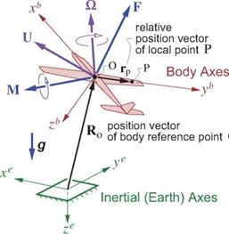
The body reference-point position vector Ro is best given by its components along the inertial Earth axes, shown as xe, ye, ze in Figure 9.2. In contrast, the local position vector r, and the body velocity and rotation

Подпись: Ue = Подпись: Щ' U Ue Axis Parameterization and Conventions Подпись: Ub' U U Подпись: = %ub Подпись: (9.3)

rate vectors U, Q are best given in the body axes xb, yb, zb, since these are also used to describe the flow about the body, e. g. via the velocity field V(r, t). To translate the individual components of any vector, such as U, from body to Earth axes, we apply the general vector transformation (F.1) derived in Appendix F.

Axis Parameterization and Conventions Подпись: cos ф —sin ф 0 sin ф cos ф 0 0 0 1 Подпись: cos в 0 0 1 sin в 0 Подпись: sin в 0 cos в Подпись: 1 0 0 0 cos ф —sin ф 0 sin ф cos ф

The direction-cosine transformation matrix Tb is now formed as the product of three simple rotation matri­ces for the individual Euler angles in the standard sequence —ф, —в, —ф:

cos в cos ф sin ф sin в cos ф—cos ф sin ф cos ф sin в cos ф+sin ф sin ф

Подпись: (9.4)cos в sin ф sin ф sin в sin ф+cos ф cos ф cos ф sin в sin ф — sin ф cos ф

— sin в sin ф cos в cos ф cos в

Подпись: b

The reciprocal conversion matrix T is composed of the reverse rotation sequence ф, в,ф. But this is also

= e

Подпись: T b Axis Parameterization and Conventions Подпись: = eT T, Подпись: (9.5)

the inverse of Tb, which is simply its transpose as derived in Appendix F for the general case.

As an application example, consider equations (9.1) and (9.2) used to obtain the gust velocity at an aircraft point P. The aircraft position Ro and the Vgust(R, t) function are typically provided in Earth axes, i. e. as RO and Vgust(Re, t), while the point P vector rp is known in body axes, as rp. Expressions (9.1) and (9.2) would therefore need to be evaluated as

RP = RO + Te rp (9.6)

Vgbustp = T eVusAR.*) (9.7)

with the final result Vgustp being in the body axes. This would then be usable for calculation of body forces and moments which are typically performed in the body axes.

Axis Systems

The orientation of the axis system used to quantify any vector or tensor is arbitrary. Common choices are to align one axis (e. g. the x axis) with either a body feature such as an airfoil chordline, or with the freestream direction. If the body is only translating, a common axis system can be used for all quantities. However, if the body is rotating, then two axis systems naturally arise:

• “Earth” axes xe, ye, ze fixed to the ground. These are non-rotating (the Earth’s rotation is neglected).

• “Body” axes xb, yb, zb fixed to the body. These rotate along with the body relative to inertial space.

Note that “frame” and “axes” are distinct concepts. For example, the aircraft position, velocity, and rotation rate Ro, U, О treated in Chapter 7 were all defined in the Earth frame. But Ro is usually expressed via its Earth-axes xe, ye, ze components, while U, О are usually expressed via the aircraft’s body-axes xb, yb, zb components. Relating them requires the axis transformation relations developed in Appendix F.

9.2 Body Position and Rate Parameters

Application of the equations of fluid motion in unsteady or quasi-steady flow situations requires specification of the velocity of every point on the body surface. This is parameterized by the inertial-frame quantities,

U(t) velocity vector of body reference point O O(t) rotation-rate vector of body

so that a point P at some location rp on the body relative to point O has the following velocity.

Up = U + Ox rp

In aircraft flight dynamics applications the atmosphere is occasionally specified to have some nonuniform “gust” velocity field VgUst(R, t), whose effect on the forces on the aircraft is to be determined. To evaluate this gust velocity at each point rp on the aircraft requires knowing that point’s Earth position within the gust field. This is parameterized by

Ro(t) position of body reference point O

ф, в, ф(р body roll, elevation, and heading Euler angles

which are sketched in Figure 9.2. The Earth position of point P and the gust velocity at that point can then be obtained from the VgUst(R, t) field.

Rp(r, t) R0(t) + rp (9.1)

Axis Systems
Axis Systems

(Vgust )p = Vgust(Rp >t) (9.2)

Figure 9.2: Aircraft motion parameters. Total aerodynamic force F and moment M are also shown.

= e = b

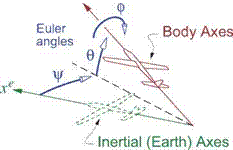
Euler angles define transformation matrices Tь or Te between body and Earth axes, developed in Appendix F.

Introduction to Flight Dynamics

This chapter will treat the key concepts and formulations used in the discipline of flight dynamics and control. The primary focus here will be on the aerodynamic characterization of the aircraft, as required for flight dynamics applications. For a complete treatment of the subject, see Etkin [65] and Nelson [66].

9.1 Frames of Reference

Description of body or fluid positions, velocities, and rotation rates requires a frame of reference for these quantities. For unsteady aerodynamics and flight dynamics, two distinct frames of reference are useful:

• An inertial “Earth” frame, either fixed to the Earth or translating uniformly relative to the Earth.

• The non-inertial “body” frame, typically fixed to the aerodynamic body of interest.

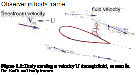
Figure 9.1 illustrates the distinction between the two frames. For steady aerodynamics the body frame is most natural, although the Earth (or airmass) frame is also useful as in the case of Trefftz-plane theory treated in Chapter 5. For unsteady aerodynamics the Earth frame is more natural because it is inertial.

Introduction to Flight Dynamics

Observer in earth frame

Optimum unswept wing

It is useful to first consider an unswept wing. We therefore assume

ce = Cl

Подпись: CDWПодпись:cd(ce, M’x>)

Cl

^t^wing ^ У)’ ^ ^West where CDwing is the wing’s profile+wave drag, and CDrest is the profile drag of the remaining fuselage, tail, and nacelle components. The objective is to find the optimum Cl, MTO combination which minimizes the Cd/МЦ2Cl fuel-burn parameter. For a numerical example we can pick

AR = 10 , CDrest = 0.025

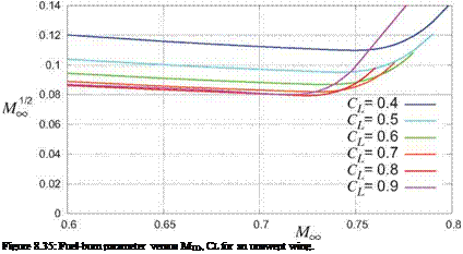
which are typical for modern jet transports. Using the 2D 12%-thick airfoil Cd Mach drag-rise sweeps shown in Figure 8.34, the corresponding fuel-economy parameters are shown in Figure 8.35. The optimum combination is roughly at

Cl = 0.8 , MTO = 0.725 (unswept-wing optimum)

Подпись: Figure 8.35: Fuel-burn parameter versus MTO, CL for an unswept wing.

although this will also depend on the airfoil thickness. A larger thickness will typically optimize to a lower Cl and a lower MTO, with a corresponding increase in the fuel-burn parameter. However, a thicker wing is structurally favorable and hence lighter, so that the WZF factor in the Breguet relation (8.175) may overcome this aerodynamic drawback and give a net benefit.

Swept-wing airfoil characterization

The earlier analysis of an infinite swept wing in Section 8.6.3 indicated that the lift depends only on the perpendicular velocity and Mach component V± = V» еовЛ and M± = MTO еовЛ. The same arguments apply to the airfoil’s boundary layers, provided we ignore the spanwise flow’s increase of the total-velocity

Reynolds number, which is reasonable for fully-turbulent flow. Consequently, the 2D airfoil lift-coefficient characteristics shown in Figure 8.34 apply to a swept wing via the following relations.

Подпись:Ml = M, cos Л ce = Cl± = Cl/ cos^

Cd = Cd(ce; Ml)

To obtain the wing’s profile drag coefficient CDwi from the 2D-section Cd value we first break down the latter into the friction and pressure components,

Cd = Cdf + Cdp (8.179)

with a roughly |, | split, respectively, being typical for transonic airfoils.

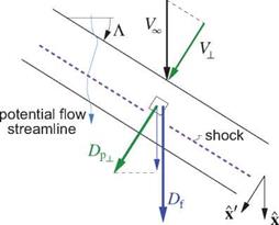
The velocity within the 3D boundary layer on the wing and hence the surface skin friction vectors Tw will be mostly aligned with the outer potential flow, which is on average parallel to the freestream velocity V, and hence the aircraft’s X direction, as indicated in Figure 8.36. This skin friction’s magnitude must also scale with the local potential-flow dynamic pressure, which scales with the freestream dynamic pressure j>.. I ‘2. This gives the following estimate for the wing’s friction drag vector.

Подпись: (8.180)Dfx = TwdS ~ pooV^Scdiyi

In contrast, the pressure forces act along the wing surface normal vectors n which lie in the plane perpen­dicular to the wing, so the pressure drag vector must be along the local chordwise vector X’ which lies in this plane. It must also scale as (>.. V2, since it must vanish in the limit of purely-spanwise flow at 90° sweep.

Optimum unswept wing Optimum unswept wing
Optimum unswept wing

Dp± Xу = ff-pn dS ~ S cdp x’ = pccV2 S cdp cos2A x’ (8.181)

Figure 8.36: Profile drag of swept wing estimated from airfoil-plane friction and pressure-drag coefficients.

Optimum unswept wing Подпись: Df + DPl cos Л Cdf + Cdp cos^ Подпись: (8.182) (8.183)

The total wing profile drag and corresponding drag coefficient are then

so that the wing’s overall profile-drag to lift ratio is

Подпись:Cbwing = Cdf + Cdv cos3A Cl cg ео82Л

which increases monotonically with sweep if 2Cdt > Cd which is invaiiably the case in the absence of sig­nificant flow separation. Hence, wing sweep by itself does not improve the wing’s drag/lift ratio, and in fact decreases it. The fuel-burn benefit from sweep instead originates from the speed/efficiency characteristics of jet engines, considered next.

Optimum swept wing

Подпись: Cp MU2 CL Подпись: Cdj + c-dv cos3A + (c£ cos2A)2/(7rAR) + Cbrest МЦ2 eg cos2A Подпись: (8.185)

Sweep introduces another design parameter into the wing design space, which is now {Cl, M00, Л}, and also includes the airfoil thickness if different airfoils are being considered. The airfoil coefficients with the above sweep corrections give the fuel-burn parameter in the form

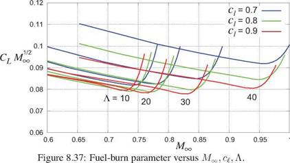
which is shown in Figure 8.37. The optimum design-parameter combination is now

cg = 0.9 , MTO = 0.825 , Л = 30° (swept-wing optimum)

and the corresponding fuel-burn parameter value of about 0.078 is smaller than the 0.080 value for the unswept-wing case shown in Figure 8.35 for a typical supercritical airfoil. The reduction is modest, but perhaps more importantly it occurs at a 0.825/0.725 — 1 = 14% greater speed which itself has economic benefits.

Optimum unswept wing

The optimum design parameters found here for the swept-wing case are quite close to what’s seen on most modern jet transports, with the exception of the cg value. In practice, lower values of cg ~ 0.75 are used for several reasons: 1) Because of local cg reductions near the wingtips, wing root, and over the fuselage, the actual airplane Cl is necessarily smaller than the infinite swept-wing value cg еов2Л. 2) Structural weight considerations favor thicker airfoils than what this aerodynamic-only optimization indicates, and thicker transonic airfoils have lower optimum cg values.