In many internal aeroacoustics problems, the mean flow is driven by a pressure gradient. For example, maintaining the nozzle flow in Figure 9.17 would require a pressure difference imposed at x1 and x2. Now, if it is required to impose at x = x1 the boundary condition p = p1 and at x = x2 the boundary condition p = p2(p is the mean flow pressure), then it would be difficult to impose additional incoming wave or outgoing wave or absorbing boundary conditions at x = x1 and x = x2. To circumvent this pressure gradient boundary condition problem, it is recommended to perform a pressure gradient transformation to absorb the pressure gradient into the governing equations. In this way, it will remove the need for enforcing a static pressure boundary condition and thus allow the imposition of inflow/ outflow or absorbing boundary conditions at the two ends of the computational domain.
Figure 9.17. Nozzle flow problem requiring the imposition of a static pressure difference at x1 and x2.
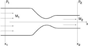
Consider the nozzle flow problem of Figure 9.17. Mathematically, the pressure gradient field may be represented by
The pressure gradient is
 d = в.
ax
Now, the following transformation of variables will move the pressure gradient boundary condition into the differential equations. Let
 v = V, p = p’, p = P + —.
Substitution of transformation (9.72) into the Navier-Stokes equations, the governing equations for (V, p’, —) in Cartesian tensor notation are found to be
dp + d(P'[12] j) = 0 91 d x ;
 9 v – ‘ 9 v
—- + v■ —- dt 1 9 x j
 +v і d—+vi5 i1e+y (p+—)^=0
The velocity boundary conditions are unchanged by the transformation. The mean pressure boundary conditions for — are
x = x1; — = 0; x = x2, — = 0.
EXERCISES

|
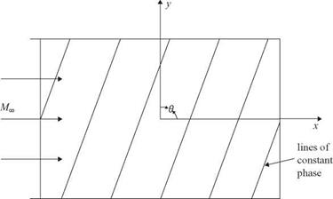
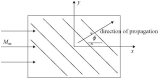
Figure 9.18. Lines of constant phase associated with plane waves in the computational plane.
|
|
 |
|
Consider plane wave solutions of the form,
|
|
|
u
|
|
|
u
|
|
|
V
|
= Re
|
|
V
|
gKax+fty-mt)
|
|
p
|
|
|
p_
|
|
|
|
|
|
|
where Re{} is the real part of. Substitution of (2) into (1) gives
|
|
 |
|
(m – MTOa)[(« – Mma}2 – a2 – в2] = 0.
|
|
|
|
 |

|
dy
dx
|
a
— = tan в.
в
|
(6)
|
|
The solution of (5) and (6) yields
|
|
|
|
ю
|
ю cot в
|
(7)
|
|
a =——- ,
MJ
|
P= Mj
|
|
Let the slope of these lines be denoted by в. Thus,
|
The mode shape is given by the eigenfunction of Eq. (3). Upon replacing a and в by Eq. (7), the vorticity wave solution may be written as
|
u
v
|
= £v
|
cos в sin в
|
cos
|
ю
— (x — cot вy — Mjt)
|
. (8)
|
|
_p_
|
|
0
|
|
_ M CO
|
|
The total wave number of vorticity wave in Eq. (8) is equal to <w/MOsin в. For convenience, let us set the total wave number to 2n or ю = 2n MOsin в. This is the same as assigning the length scale L to be equal to the wavelength.
Use a 200 x 200 mesh as the computation domain. Choose a suitable size Ax and Ay. Propagate a plane vorticity wave across the computation domain with в = 60° and sv = 10—5. You may add artificial selective damping if needed. Compare your numerical result with the exact solution. Find the maximum error over the entire computation domain over a period of oscillation.
9.2. This is a continuation of Problem 9.1. Now suppose one is interested in acoustic wave propagation. The dispersion relation is
(ю — MOa)2 — a2 — в2 = 0
or
ю = MO a + (a2 + в2)2 (1)
(the negative sign of the square root gives a second acoustic mode).
Let V and ф be the velocity and direction of propagation. Then, from the group velocity, it is easy to find
da = M° + (a2+в2 )1/2 = V cos ф (2)
If the direction of propagation ф is specified (see Figure 9.19), then the solution of Eqs. (1) to (3) gives
V = Mm cos ф + (1 — MJ sin2 ф)2 (4)
 oj(V cos ф — MTO)
1 + MTO (V cos ф — MTO)
юУ sin ф
1 + MTO (V cos ф — MTO)
The eigenfunction for the acoustic wave is given by the solution of Eq. (3) of Problem (9.1). It may be written in the following form:

 (7)
(7)
where V, a, and в are given by Eqs. (4), (5), and (6), and sa is the amplitude of the acoustic wave. It is easy to show that the total wave number is equal to ш /[1 + MTO(Vcosф – MTO)]. Thus, by taking ш = 2n[1 + MTO(Vcos<p – MTO)], the acoustic wavelength is chosen as the length scale.
Use a 200 x 200 mesh as the computation domain. Choose a suitable mesh size, propagate a plane acoustic wave train across the computation domain with <p = 30° and ca = 10-5. Compare your numerical results with the exact solution. Find the error distribution across the computation domain.
9.3. Many flow and acoustic problems are quasi-two-dimensional. This happens when the flow spreads out very slowly. A good example is the case of a jet. Locally, it makes sense to assume that the jet flow is parallel, that is, the velocity is parallel and independent of the axial coordinate x.
Consider the scattering of an incident plane acoustic wave by a jet. Let the mean axial velocity and the density of the jet be u(y, z) and p(y, z), locally parallel flow assumed. p is a constant. The linearized Euler equations are
d и _9 и d и d и 1 9 p
+ и + v + w + = 0
dt dX dу dz p dx
9 v _9v 19p
+ и + = 0
91 dx p у
d w _9 w 1 9 p
+ и + = 0
dt dx p z


dp dp
+ U + kp 91 dx
Let the incident plane acoustic wave be
i – (cos ©x+sin © sin фу+sin © cos фz—aJt)
p = ea0

where (©, ф) are the angular coordinates of the direction of propagation with respect to a spherical polar coordinate system centered at the jet exit, and a0 is the ambient sound speed.
Since the coefficients of Eq. (1) are independent of x, the x dependence of the scattered field must be the same as the incident wave. By factoring out exp[i(Q/a0)(cos©)x], the governing equations for the scattered sound field has spatial dependence on y and z only. Outside the jet (see Figure 9.20), where й = 0, the equations reduced to
dй iQ cos ©
+ p = 0
dt a0 P0
w + 1 3p = 0
dt P0 dy
д w 1 d p „
+ = 0 d t p0 d z

 д v d w
й + — + = 0.
dy dz
It is easy to show that (3) forms a dispersive wave system. The asymptotic solution of a dispersive wave system is not suitable for constructing radiation boundary condition.
Develop a set of PML absorbing boundary condition for Eq. (3) to be used in the boundary region of a computation domain as shown in the figure. The PML is to absorb the scattered waves. Show that your PML equations are stable.
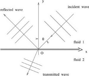
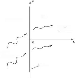
9.4. This problem is intended to test the discrete formulation and computation of sound transmitted through a surface of discontinuity. Here, the surface of discontinuity is formed by the interface of two fluids with different densities and sound speeds as shown in Figure 9.21. An incident acoustic wave at an angle of incidence в impinges on the interface. Part of the wave is transmitted and part of it is reflected. For computation purposes, we will use the following length, velocity, time, pressure,
Figure 9.21. Schematic diagram showing the incident, the reflected, and the transmitted waves.
 and density scales. Subscripts 1 and 2 indicate fluids 1 and 2. length scale = L
velocity scale = a1 (sound speed in region 1) L
time scale = —
 a
a
density scale = p 1 (density of ‘uid in region 1) pressure scale = p1a1
P1 Y1
The governing equations for small-amplitude disturbances in fluid 1 are
дР1 + ( дЩк + = 0
дt дх ду ‘
The governing equations for small-amplitude disturbances in fluid 2 are
Pi = P2’ vi = v2-
Now, consider a plane wave at an incident angle 0 and frequency ы given below:
|
P1~
|
|
1
|
|
u1
|
|
– sin 0
|
|
= Re
|
– cos 0
|
|
v1
|
|
|
P1-
|
incidence wave
|
1
|
where Re is the real part of. Determine the intensity and direction of the transmitted and reflected waves for the two cases with 0 = 20° and 65°. The frequency and other parameters are ы = 0.7, a = 0.694, and X = 1. Plot contours of p at intervals of 0.25 at the beginning of a cycle.
The exact solution is given in Section 1.4. At 0 = 65°, there is a total internal reflection. The transmitted wave amplitude is complex indicating that there is no transmitted wave radiated to the far field.
(Hint: In this problem, although both p and v are continuous at the vortex sheet their y derivatives are, however, discontinuous. Because of the discontinuous derivatives, one may use the ghost point method to enforce the continuity of p and v.)
9.5. For the purpose of computing sound radiation from a conical surface with a half cone angle 5 as shown in Figure 9.22, a set of natural coordinates to use is (f, n, Ф), where f and n are related to the cylindrical coordinates (r, х, ф) by
f = x/ cos 5, n = r – x tan 5.
(f, n) are, in fact, the body-fitted oblique Cartesian coordinates in the ф = constant plane. By assuming the solution to have a еітф dependence, show that, when еітф is
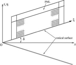 Figure 9.22. Oblique Cartesian coordinates (f, n) and a PML on a conical surface.
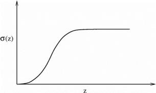
Figure 9.23. Profile of damping function a(z).
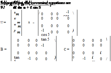
A subscript m is used to denote the solution associated with. (um, vm, wm) are the velocity components in the cylindrical coordinates. For computing sound radiation, it is proposed to use PML as boundary condition. The PML encloses the computational domain as shown in Figure 9.22.
Show that an appropriate set of PML equation is
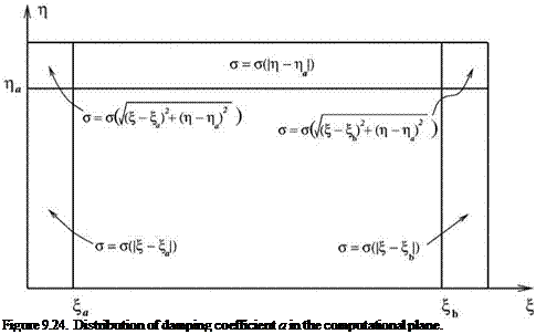
where a (z) is a damping function with a profile as shown in Figure 9.23. The distribution of this function in the computational plane is shown in Figure 9.24.
Implement the PML equations to test their effectiveness. You may use an oscillating point monopole located at the center line of the conical surface as the source of sound.
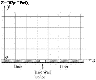
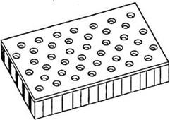 both positive or negative depending on the frequency. For many acoustic liners, the dependence of X on angular frequency ы can be represented adequately by a simple analytical expression of the following form (Tam and Auriault, 1996):
![]() X _ X-1 + X
X _ X-1 + X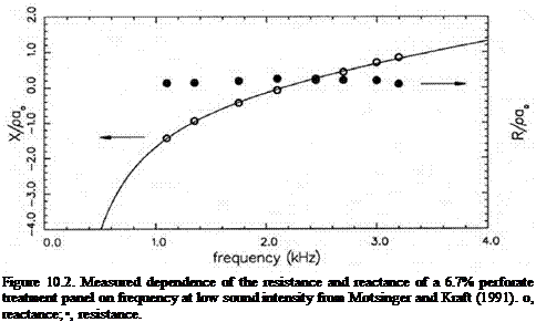


 9 v – ‘ 9 v


 and density scales. Subscripts 1 and 2 indicate fluids 1 and 2. length scale = L
 a
a

 Figure 9.22. Oblique Cartesian coordinates (f, n) and a PML on a conical surface.


 dp dp du dv
 . _ . dp du _______
 interface
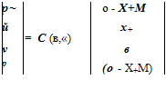


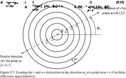
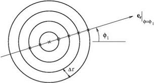
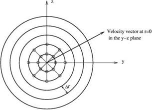 points at angle ф = ф1 and r = nAr, the velocity components in the directions of the cylindrical coordiates and in the y and z direction are related by
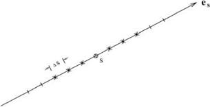
 Here, ЭФ/Эз = es – VФ is the directional derivative of Ф in the es direction. j = 0 is the point at which the derivative is to be computed.

 where pn, pn, etc. are the amplitude functions of the Fourier series expansions in ф.