Category COMPUTATIONAL AEROACOUSTICS

Outflow Boundary Conditions: Further Consideration

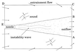
In many CAA simulations, the boundary of the computation domain cuts across an outflow. An example is the case of simulating jet noise generation as shown in Figure 9.2. Since numerical boundary conditions imposed at the outflow boundary must reproduce all the external effects on the flow field inside the computational domain, the outflow boundary is usually placed sufficiently far downstream of the nozzle exit to avoid significant upstream influence of the jet flow left outside. In the jet noise simulation problem, as in many other problems, the mean flow is not known a priori. The numerical boundary conditions are required to capture the mean flow as well as to be transparent to the outgoing acoustic, vorticity, and entropy waves.

At present, many CAA boundary conditions are formulated under the assump­tion that the mean flow is known. Their main concern is to avoid any reflection of the outgoing unsteady disturbances. Dong (1997) recognized the need for CAA outflow boundary conditions to be capable of capturing the mean flow correctly as well. He proposed a set of asymptotic outflow boundary conditions based on sink/source flows. In two dimensions, these conditions are as follows:

1 dp dp 2

—– 77 + 7—— + – (p – px) = 0

ax dt 9 r r

1 9 и 9 и и

———– 1—— + – = 0

ax dt 9 r r

1 9 v 9 v v

———– 1—— + – = 0

ax dt 9r r

Подпись: (9.6)Подпись:1 9 p 9 p 2/

—– 77 + 7—— + _ (p

ax dt 9r r

Подпись: (9.7)

where r is the radial distance in polar coordinates, and px, px, and aX are the ambient pressure, density, and sound speed, respectively. Dong derived this set of outflow boundary conditions by noting that the asymptotic solution of a time – independent localized source in two dimensions, denoted by an overbar, is

Подпись: 1 r 2 Подпись: + °(r2) . Подпись: (9.8)

where Q is the source strength, у is the ratio of specific heats, and vr is the radical velocity component. It is easy to verify that Eq. (9.7) is a solution of Eq. (9.6) to order O(r-4). On the other hand, the asymptotic solution of outgoing acoustic waves in two dimensions without mean flow (see Eq. (6.1)) is

By substitution of asymptotic solution (9.8) into Eq. (9.6), it is easy to find that Eq. (9.6) is satisfied to order O(r-3/2). It has been pointed out that Eq. (9.6) is very similar to the asymptotic boundary conditions of Chapter 6, Eq. (6.14). The major difference is in the numerical coefficients of the 1 /r terms. It is straightforward to see that the asymptotic solution of the mean flow of a localized source and that of the outgoing acoustic waves have different dependences on r. Eq. (9.6) as an outflow boundary condition is a reasonable compromise.

Outflow boundary condition (9.6) may be generalized to three dimensions. The corresponding equations in spherical polar coordinates (R, в, ф) are as follows:

1_ dp + дР + 3(P – ) = 0

дt дR R

1 дU дU 2u

— Ч7 + Т5 + – ІЇ = 0 aTO dt д R R

1 д V д V 2v

—– ~я7 + lyn + 17 = 0

a^ д t д R R

Подпись: = 0 = 0.Подпись:1 д W д W 2w

am д t д R R

1_ др + др + 3(p – )

aTO дt д R R
Подпись: (9.10a) (9.10b) (9.10c) (9.10d) (9.10e)

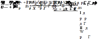
Jet flows are not source flows. Boundary layer arguments as well as experi­mental measurements suggest that the static pressure across a jet far downstream is practically constant and is equal to the ambient pressure. In this case, p = pTO is a good mean flow pressure boundary condition. This is the steady-state solution of the jet outflow boundary condition. Now, if the outflow boundary conditions (6.13) are nonlinearized, i. e., replacing the linear convection term и0(дu/дх) by the full convection terms etc., it is easy to arrive at the following set of nonlinear outflow boundary conditions. Written in cylindrical coordinates (r, ф, x), they are

where V(e) = и cos в + a(1 – sin2e)1/2 and M = и/a; a = (yр/р)112 is the speed of sound; and (R, в, ф) are the spherical polar coordinates with the polar axis coinciding with the centerline of the jet. For the mean flow, р = рто is a solution for Eq. (9.10e). Eqs. (9.10b), (9.10c), and (9.10d) are identical to the momentum equations of the Euler equations. They should yield the correct velocity field. For a time-independent solution, Eq. (9.10a) reduces to

Подпись: (9.11)др др W др

и—— v——- ——– = 0.

дх дГ Г дф

Eq. (9.11) is the same as р = constant along a streamline. This should be rea­sonably good for jet flow far downstream where there is no intense mixing. Thus, outflow boundary conditions (Eq. (9.10)), although originally designed for outgoing disturbances alone, are also capable of capturing the mean flow of a jet.

Now, outflow boundary conditions (9.9) and (9.10) are very different. Each is designed specifically for a class of outflows. If the mean flow is source-like, then use Eq. (9.9). On the other hand, if the mean flow is jet-like, then Eq. (9.10) would be more appropriate.

Entrainment Flow

In performing numerical simulation of practical problems, sometimes one is forced to use a relatively small computation domain. This may be because of computer memory constraint or the need to reduce computation time. In these cases, flow into or out of the scaled down computational domain could be due to the influence of sources or forces located outside as well as inside the computational domain.

Figure 9.2. Computational domain for numerical simulation of jet noise gen­eration.

image115To maintain an accurate simulation, it is necessary to develop special boundary conditions to account for these effects on the flow inside the computational domain.
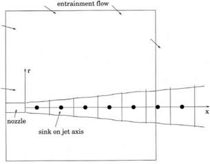
As an example, consider simulating a jet flow and noise radiation as shown in Figure 9.2. For practical reasons, the size of the computational domain is typically thirty to forty jet diameters in the axial direction and twenty to thirty diameters in the radial direction or smaller. These dimensions are somewhat smaller than those of a typical anechoic chamber used in physical experiments. Because of the proximity of the computation boundary to the jet flow, the boundary conditions along boundary BCDE are burdened with multiple tasks. Obviously, the boundary conditions must be transparent to the outgoing acoustic waves radiating from the jet. In addition, the boundary conditions must impose the ambient conditions on the numerical simulation. In other words, they specify the static conditions far away from the jet. Furthermore, the jet entrains a large volume of ambient gas. The entrainment flow velocity at the computational boundary, although small, is not entirely negligible. For high-quality numerical simulation, the boundary condition must, therefore, allow an as yet unknown entrainment flow to enter or leave the computational domain smoothly as well.

In Section 6.5, a set of radiation boundary conditions for nonuniform mean flow is provided. Let p, U, v, and p be the weakly nonuniform mean flow at the boundary region of the computational domain. The radiation boundary condition in three-dimensional cylindrical coordinates may be written as

Подпись: = 0,(9.4)

where (r, ф, x) are the cylindrical coordinates, в is the polar angle in spherical coordinates with the x-axis (flow direction of the jet) as the polar axis, and (u, v, w) are the velocity components in the axial (x), radial (r), and azimuthal (ф) directions.

V(в, r) = Ucos в + v sin в + [a2 – (v cos в — Usin в)2]/2, and a is the speed of sound.

Figure 9.3. Determination of the en­trainment flow of a jet by the point-sink approximation.

image116

Подпись: Q2 Подпись: + • Подпись: (9.5)

Note that the entrainment flow at the boundary region of the computation domain would be influenced by the jet flow outside the computational domain as well as inside. To develop an asymptotic entrainment flow solution, a simple way is to divide the jet into many slices as shown in Figure 9.3. The energetic portion of a jet may extend, depending on jet Mach number, beyond the computation domain to about forty diameters downstream. The mass fluxes across the boundaries of each jet slice may be found from available empirical jet flow data. The difference in mass fluxes at the two ends of each slice of the jet gives the amount of entrainment flow for the particular slice. This entrainment may be simulated by a point sink located at the center of the slice. The asymptotic solutions for a point sink located on the x-axis at xs in a compressible fluid is given by (a subscript “e” is used to indicate entrainment flow)

where pm, am, and y are the ambient gas density, the sound speed, and the ratio of specific heats, and Q is the strength of the sink. It has dimensions of pmamD2 where D is the jet diameter. On replacing (p, u, v, p) of Eq. (9.4) by (pe, ue, ve, pe) of Eq. (9.5) and upon summing over the contributions from all the sinks to approximately 60D downstream from the nozzle exit, the desired radiation-entrainment flow boundary conditions are obtained.

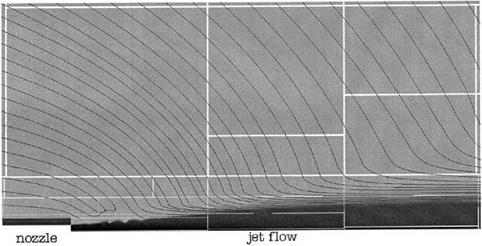
Figure 9.4 shows the entrainment flow streamlines of a Mach 1.13 cold jet from a convergent nozzle computed using the radiation-entrainment flow boundary condi­tion. It is worthwhile to point out that along the right-hand boundary BC, the mean

image117

Figure 9.4 Computed streamlines of the entrainment flow around a supersonic screeching jet at Mach 1.13. White lines separate different computation blocks.

flow actually flows out of the computational domain, exactly as observed in free jet experiments. The streamline pattern would be vastly different had the entrainment flow outside the computational domain not been included in the sink flow compu­tation. If the sinks outside the computational domain are excluded in forming (p, U, v, p) then a recirculation pattern would emerge. This, however, is inconsistent with experimental observations.

In this jet flow and noise radiation example, the jet may be subsonic and super­sonic. For a subsonic jet, the nozzle exit pressure is nearly equal to ambient pressure, but for supersonic jets operating at off-design conditions, the pressure at the nozzle exit is quite different from that at ambient pressure. In this case, it is vital that the boundary conditions can communicate to the computation what the ambient pres­sure, density, and temperature are. Radiation boundary conditions (9.4) allow the specification of an ambient condition. The time-independent solution of (9.4) is и = U, v = v, p = p, andp = p. Many other radiation boundary conditions, designed with different objectives in mind, do not allow the imposition of an independent ambi­ent condition. If these boundary conditions are used for computing an imperfectly expanded jet, the jet will not expand properly in the simulation.

Boundaries with Incoming Disturbances

In many aeroacoustics problems, there are disturbances that enter the computational domain through the outer boundary. For example, in computing the scattering char­acteristics of an object, acoustic waves must be allowed to pass through the boundary of a computational domain in a specified direction and intensity. The scattering phe­nomenon produces scattered waves. These waves are radiated in all directions. They propagate to the far field as outgoing waves through the boundary of the compu­tational domain. In this case, the boundary condition of the computational domain must take on the responsibility of generating the incoming sound and, at the same time, they also serve as radiation boundary conditions for the scattered waves. To handle the dual role, a split-variable method has been developed. The essence of this method is discussed below.

The equations governing the propagation of small-amplitude disturbances are the linearized Euler equations. Both the incoming disturbances and the outgoing scattered waves are solutions of these equations. However, in a scattering problem, incoming disturbances are known or specified, whereas the scattered outgoing waves are unknown. To illustrate the basic concept of the split-variable method, consider a two-dimensional problem with a uniform mean flow velocity u0 in the x direction.

image113,image114

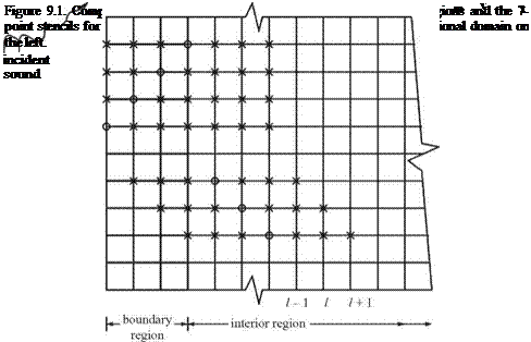
It will be assumed that the incoming sound waves enter the computational domain from the left boundary as shown in Figure 9.1. The variables associated with the incoming waves are labeled by a subscript “in” and variables associated with the outgoing scattered waves are labeled by a subscript “out.” In the left boundary region of the computational domain, the total variables are the direct sum of the incoming and outgoing disturbances; i. e.,

p"

Pin _

p out

u

=

uin

+

Uout

v

vin

vout

P-

Pin-

Pout

Подпись: Pout Uout vout Pout Подпись: 0 + 0 (r-2) , (9.2)

In Eq. (9.1) the variables associated with the incoming disturbances are known. They are prescribed by the physical problem. The aim is to compute the outgoing scattered waves. In the boundary region (see Figure 9.1), the outgoing acoustic waves are governed by the radiation boundary condition or Eq. (6.2). That is,

where V(в) = [u0 cos в + (a0 – U sin2 в)1/2] and a0 is the speed of sound.

In the interior region, the small-amplitude disturbances are governed by the linearized Euler equations (see Eq. (5.1)). They are

9 U 9 E 9 F

dt + dx + 9 y

where

Подпись:(9.3)

Note that the distinction between incoming and outgoing waves is lost once the point of interest is not in the boundary region of the computational mesh.

To compute the numerical solution, Eq. (9.3) is discretized by the 7-point stencil dispersion-relation-preserving (DRP) scheme. These discretized equations are used to determine the full physical variables (p, u, v, p) in the interior region. At the same time Eq. (9.2) is discretized again by the 7-point stencil DRP scheme. These discretized equations are used to calculate the outgoing waves (pout, uout, vout, pout). They are applied only in the boundary region. Before the computation can be implemented, however, one must recognize that once the 7-point stencil DRP scheme is applied to Eq. (9.2), the finite difference stencil in the x direction would extend outside the boundary region into the interior region as shown in Figure 9.1. In the interior region, only the full variables (p, u, v, p) are computed. But (pout, uout, vout, pout) are needed at the extended stencil points to support the computation. To find these quantities, one may use Eq. (9.1). Since the incoming disturbances are known, the outgoing wave variables can be found by subtracting the incoming disturbance variables from the full variables at mesh points near the outer boundary of the interior region.

Now, in computing the full variables (p, u, v, p) in the interior region, one would encounter a similar problem. For mesh points in the three columns closest to the boundary region, the 7-point stencil will extend into the boundary region where only the outgoing disturbances are computed. To find the values of the full variables in the boundary region, one may again use Eq. (9.1) by adding the known incoming disturbances to the computed outgoing waves. In this way, the variables in the entire computational domain can be marched forward in time. It is straightforward to see that the split-variable method essentially converts the boundary region into a source of the incoming disturbances. At the same time, it acts as radiation boundary condition for the outgoing scattered waves.

Advanced Numerical Boundary Treatments

Подпись: 9High-quality boundary conditions are an essential part of computational aeroacous – tics (CAA). Because a computational domain is necessarily finite in size, numerical boundary conditions play several diverse roles in numerical simulation. First and foremost, they must assist any outgoing disturbances to leave the computational domain with little or no reflection. The alternative is to use a perfectly absorbing layer as a numerical boundary treatment. Such a layer absorbs all outgoing distur­bances without reflection as in the case of an anechoic chamber. In addition, if the problem to be simulated involves incoming disturbances, then these disturbances must be generated by the boundary conditions prescribed at the outer boundary of the computational domain. Furthermore, if there are flows that are originated from outside the computational domain, they must be reproduced by the boundary treat­ment as well. In this chapter, methods to construct numerical boundary conditions that perform these various functions are discussed.

Variable Artificial Selective Damping

Now the origin of the spurious spatial oscillations around a computed shock solution is known; what is needed to obtain an acceptable nonlinear solution is to eliminate the short waves around the peak at a Ax = apeak Ax. One way to do this is to use artificial selective damping, which was discussed in Chapter 7. For a nonlinear wave

image103
propagation problem, artificial selective damping is needed only in the limited region of space where large gradients occur. The use of a constant artificial viscosity, which introduces uniform damping everywhere, is not a good strategy. For a high-quality numerical solution, the use of a variable artificial viscosity or mesh Reynolds number is desirable.

To establish a variable damping algorithm, a way to measure the shock strength or velocity gradient is needed. A shock is expected to be smeared out over a few mesh points, so the relevant measure of length is Ax (the mesh size). As a measure of velocity, one may use wstencil = |wmax – wmin|; the difference between the maximum velocity, wmax, and the minimum velocity, wmin, within the stencil. Note: if a very large stencil is used in the finite difference scheme, one might consider restricting

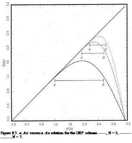
Подпись: Figure 8.5. a Ax versus a Ax relation for the DRP scheme. , N = 3; , N = 5, N = 7.

the determination of umax and umin to a smaller substencil in forming ustencil. It is useful to define a stencil Reynolds number, Rstencil, by

Rstencil = UstefAX. (8.34)

Подпись: dut dt image105 Подпись: (8.35)

On adding artificial selective damping terms to the discretized nonlinear simple wave equation (8.12), it is straightforward to find (in dimensional form) the following:

Подпись: magnitude of nonlinear steepening term magnitude of damping terms

In Eq. (8.35), the ratio of the magnitude of the nonlinear steepening term to the damping term is (Note: velocity scale is ustencil) as follows:

So Rstencil may be interpreted as the rate of generation of spurious short waves around a Ax = apeak Ax to the rate of removal of the short waves by artificial selective damping. What one would like to see is that, as soon as the spurious waves are

image106

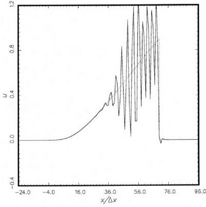
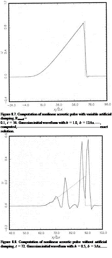
Figure 8.6. Computation of nonlinear acoustic pulse without artificial damping. t = 36. Gaus­sian initial waveform with h = 1.0, b = 12 Ax.—————————————————————- , computed,…………. exact solution.

generated, they are eliminated by damping. In other words, the generation and damping processes are matched or balanced. This means that ^stencil is a universal constant. Here, a universal constant means that it is independent of the nonlinear problem to be solved. However, the value of the constant obviously depends on the damping curve and the finite difference scheme being used.

To find ^stencil for the 7-point stencil DRP scheme and a damping curve of half­width 0.3n, extensive numerical experiments have been carried out. It is found that by taking ^stencil — 0.06 to 0.1 most of the preshock and postshock spurious spatial oscillations are removed from the numerical solutions for all the initial pulse profiles that have been considered.

Two numerical examples are provided here. Figure 8.6 shows the computed waveform at t = 36 (in Ax/a0 units) when no artificial selective damping terms are included. The initial pulse profile is a Gaussian with h = 1.0 and b = 12. The waveform is clearly dominated by spurious spatial oscillations bearing little resemblance to the exact solution. Figure 8.7 is the computed solution with artificial selective damping terms. ^stencil is set at 0.1 (for general application, ^stencil = 0.06 gives the best overall results). The numerical solution compares favorably with the exact solution with a fitted shock according to the Whitham (1974) method. Figure 8.8 shows the case with h = 0.5 and b = 3. At t = 72 the numerical solution without artificial selective damping consists of random spikes. The computed results seemingly have no relationship to

result with variable damping (Rstencil = 0.1). The computed shock matches well with the exact solution. The shock is smeared out approximately over five mesh spacings.

Concerning whether one should put the governing equations of gas dynamics in a conservation form before computing the solution using the variable damping method for shock capturing, extensive testing indicates that this is a requirement if an accurate solution is to be obtained. Test results reveal that the use of governing equations in nonconservation form often leads to a slower propagation shock. This is, perhaps, not altogether surprising since in gas dynamics the shock speed depends on the conservation of mass, momentum, and energy across the shock.

EXERCISES

8.1.

Подпись: — + u— = 0 (nonconservation form)

The inviscid Burger’s equation can be written in a conservation or nonconser­vation form

Solve these equations computationally using the variable damping method with the initial condition,

t = 0 u = 0.5e~(ln2)( 5)

where Ax = 1.

Assess the accuracy of the two solutions, especially the location of the shock as a function of time by comparing the solutions with the shock-fitted solution following Whitham’s equal area rule (see Whitham (1974) section 2.8).

8.2.

Solve the simple nonlinear wave equation,

with initial condition, t = 0

Подпись: u = 0.5 expimage11121

by adding variable damping to the numerical scheme. Compare the solutions obtained using a 7-point stencil and a 15-point stencil (using the same size damping stencil as the computation algorithm). Compare the time history of the shock with that obtained by Witham’s equal area rule.

8.3. In dimensionless form with respect to the following scales:

length scale = Ax velocity scale = aref time scale = Ax/aref density scale = pref pressure scale = pref.

the Euler equations in one dimension are

where E = . p 1 u2.

(Y-1)p 2

Solve the shock tube problem using the following initial conditions and a com­putation domain -100 < x < 100, t = 0, u = 0:

, x < -2

4.4 (

((x + 2) n

2.7 + 1.7 cos 1—— 4—–

-2 < x < 2

1

, x > 2

p = (YP)1/Y, Y

= 1.4.

p=

Find the spatial distribution of p, p, and u at t = 40, 50, 60, and 70. Compare your numerical solution with the standard shock tube solution.

Spurious Oscillations: Origin and Characteristics

Consider the computation of the solution of the nonlinear simple wave equation (8.12) by a high-order finite difference scheme. For this purpose, it is more convenient to use dimensionless variables with mesh size Ax as the length scale, speed of sound a0 as the velocity scale, and Ax/a0 as the time scale. On recasting (8.12) into a conservation form, the initial value problem is

Подпись: (8.17)д u д u y + 1 д u2

—– 1—— + —л——– = 0

д t д x 4 дx

3 , 1 3

a u{n) – Y + 1 aiuj+t 4

Consider the initial condition in the form of a Gaussian function as follows:

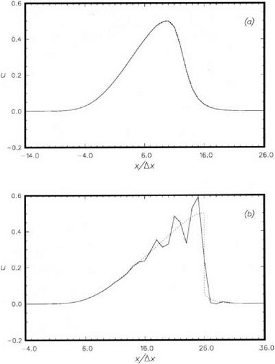
The solution of Eq. (8.19) with initial condition (8.21) can be computed easily. Figure 8.2 shows the computed results for the case h = 0.5 and b = 5.0 at t = 6 and t = 16. At t = 6, the waveform, unlike the initial shape, is no longer symmetric about its maximum. It has been substantially distorted by nonlinear steepening effects. The waveform is in good agreement with the exact solution. t = 6 is very near to the wave breaking time when a shock will form.

At t = 16, a shock has formed in the exact solution. Clearly, the high-order finite difference scheme cannot reproduce a sharp discontinuity. The shock is replaced by a steep gradient. However, following the steep gradient are spurious spatial oscil­lations. The presence of these spurious oscillations renders the numerical solution totally unacceptable.

The spurious oscillations are not related to the Gibbs phenomenon as many investigators had speculated. What causes the spurious spatial oscillations then? It turns out that a good deal of the understanding of the origin of the spurious oscillations can be found by studying and comparing the time evolution of the exact and finite difference solutions in wave number space.

33

EY + 1 , ,2

ajuj+i + E aj(uj+i)

j=-3 4 j=-3

Подпись: =0 Подпись: (8.22) (8.23)

The Fourier transform of Eq. (8.17) and initial condition (8.20) is

image101

Figure 8.2. Comparisons between computed and exact solutions of the nonlinear simple wave equation. exact, DRP scheme. (a) t = 6.0, (b) t = 16.0.


This is a special case of the following finite difference differential equation in which x is a continuous variable.

3 3

d lu (x t ) y + 1

Подпись: 4 1 i=-3 Подпись: dt’ + ^2 aju (x + i^x, t) + ^—4— ^2 aju2 (x + j&x, t) = 0. (8.25)

i=-3

Подпись: = 0, Подпись: (8.26)

The Fourier transform of Eq. (8.25) is

where a (a ) is the wave number of the finite difference scheme.

Both Eqs. (8.22) and (8.26) with initial condition (8.23) describe the time evolu­tion of a nonlinear acoustic pulse in wave number space. Eq. (8.22) is for the exact

solution. Eq. (8.26) is for the finite difference equation. These nonlinear integral- differential equations can be solved numerically by first discretizing the wave number axis into a fine mesh of spacing Да. The integrals are then converted to sums. This reduces the equation to a system of (2M + 1) first-order ordinary differential equa­tions in time, where M is a large integer.

Eqs. (8.22) and (8.26) become, upon discretizating the а-axis,

Подпись: ' j , _ (тЬДа) hbe 41q2 . Подпись: (8.29)

where т = – M, – M + 1,…, M, and, U j = U j = 0 if j > M. The initial condition is

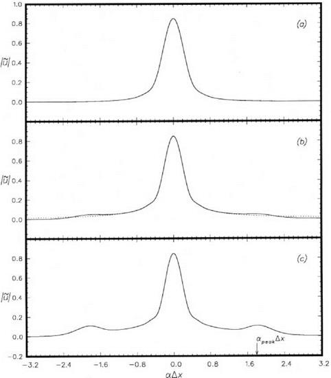
The systems of Eqs. (8.27) and (8.28) with initial condition (8.29) can be inte­grated in time numerically by the Runge-Kutta method. The computed results are shown in Figure 8.3 for the case h = 0.5 and b = 5.0. The time evolution of the pulse in physical space is given in Figure 8.2. At t = 6, the wave number spectrum is smooth and nearly Gaussian as shown in Figure 8.3a. There is very little differ­ence between the exact and the finite difference solution. At t = 11.67, the shock formation time, the wave number spectra are shown in Figure 8.3b. The computed and the exact wave number spectra are no longer identical. A small spurious peak appears at а Дх = 1.8 for the finite difference solution. This peak grows in height as time progresses. At time t = 16, a significant peak has developed as can be seen in Figure 8.3c.

In the physical space, Figure 8.2b, the dominant wavelength of the spurious spa­tial oscillations is about 3.5Дх. The corresponding wave number is аДх = — 1-8.

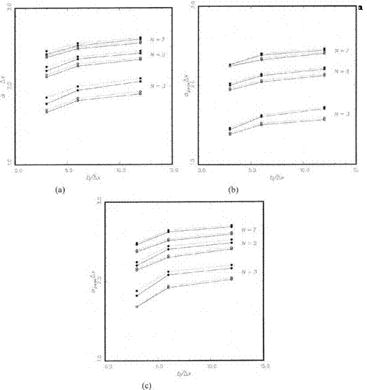
Clearly, the accumulation of wave energy around the spurious peak in the wave num­ber space is the cause of the appearance of the extraneous spatial oscillations in the waveform in physical space. Let us now determine the factors that could significantly influence the wave number at the maximum of the spurious peak, namely, а^. A list of the likely factors is as follows:

1. The initial waveform of the acoustic pulse.

2. Whether the equation is cast in conservation form or nonconservation form.

3. The size of the finite difference stencil, N.

To test the effect of the initial waveform, the following families of initial profile shapes will be considered.

(a) Gaussian Profile

image102

Figure 8.3. Time evolution of the wave number spectrum of an acoustic pulse………. exact

solution,____ DRP scheme. (a) t = 6.0, (b) t = 11.67, (c) t = 16.0.


(b)

The Lorentz Line Shape

Each of these waveforms is characterized by two parameters, namely, h (the maximum amplitude) and b (the half-width). For each initial waveform, the systems


where к(k) is a (a) with a ^ k, is integrated in time. The location apeak Ax in wave number space using stencil size N = 3,5, and 7 are determined computationally. The results are given in Figures 8.4a, 8.4b, and 8.4c. These results suggest the following conclusions.

1. Whether the governing partial differential equation is cast in conservation form or not has only a minor effect on the location of apeak Ax.

2. The initial profile shape of the waveform has a stronger influence than whether the equation is in conservation form or not.

3. The stencil size has the dominant influence. The value of apeak Ax shifts to higher values with increase in stencil size.

A different presentation of this result is given in Figure 8.5. It is found that apeakAx invariably lies in the range marked AB in the a Ax versus a Ax plot. Two other important points are observed. (a) Point A is nearly equal to ac Ax so that the wave number of the spurious spectrum peak is definitely in the short wave range. (b) apeakAx lies close to where a Ax is largest. It is not difficult to understand these results. The term и(ди/дx) or 1/2(дu2/Bx) in the partial differential equation is the nonlinear steepening term. It causes the solution to cascade to finer and finer scales or higher wave numbers. For the finite difference scheme, the nonlinear term in wave number space is

a j їй (k, t) U (a — k, t )dk

— TO

This is weighted by a so that it favors the transfer of energy to wave numbers for which a is the largest.

Once energy cascades into this wave number range, further cascading is pre­vented by the dispersive nature of the numerical waves. Dispersive waves propagate with different wave speeds. This reduces the effectiveness of nonlinear interaction and hence the cascading process. This is why the wave energy piles up around wave number apeak Ax without cascading to even higher wave numbers.

Computation of Nonlinear Acoustic Waves

image100

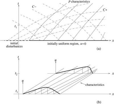
Figure 8.1. (a) The P, C+, and C— characteristics in the x — t plane. (b) Characteristics of equation (8.13) and nonlinear steepening of the wave front.


Now consider the problem of acoustic waves propagating into a region initially at rest; i. e., t = 0, u = 0, p = p0, a = a0. Without loss of generality, it will be assumed that the waves propagate in the positive x direction. Since this region is covered by the P characteristics that start out from the same initially undisturbed region (see Figure 8.1), the isentropic relation

dp dp 2 = a = da p a p y — 1


P_

pY


£0

P0


(8.8)


or


holds throughout the region. The same is true with the C characteristics. By elimi­nating dp/pa from Eqs. (8.7) and (8.8), it is found that

(8.9)


Upon integrating Eq. (8.9) and noting that the constant of integration is the same for all points in the region, the following integral relation is obtained:

Подпись:2a 2a0

— u = – Y — 1 Y — 1

Now, in the region of the x — t plane covered by both the P and C— characteristics starting from the initially uniform region, Eq. (8.2) may be cast into the following form, by means of the relation (8.7) of the C characteristics:

Подпись: 9 u ~dt+ (u + a) — 0.

9 x

Finally, by combining Eqs. (8.10) and (8.11), it is easy to derive the nonlinear simple wave equation as follows:

d u / Y + 1

Tt + ( “°+ ~u


A = 0.

д X


(8.12)


Eq. (8.12) is a nonlinear first-order partial differential equation for u. The char­acteristic system of this equation is

dx y +1

Подпись: 2—— = «0 +– ~— u

dt 0

Подпись: (8.13)du 0 dt

The two equations of (8.13) can be integrated easily. Suppose the initial con­dition is

t = 0, u = <h(x). (8.14)

The integral of the second equation of (8.13) satisfying the initial condition is

t = 0, x = s, u = Ф(5). (8.15)

This means that u is a constant along a characteristic. Because u is a constant along a characteristic, the right side of the first equation of (8.13) is a constant. The integral of this equation is

x = s + ^a0 +Y 2 1 Ф^)^ t. (8.16)

The solution of the nonlinear simple wave equation (8.12) and initial condition (8.14) may now be found by eliminating the parameter s from Eqs. (8.15) and (8.16). Eq. (8.16) indicates that the characteristics are straight lines in the x – t plane. The slopes of the characteristics, however, depend on Ф^). If Ф^) is not a constant, the slope of the characteristics will vary from characteristic to characteristic (see Figure 8.1b). Note that adjacent straight lines that are not parallel but convergent will eventually intersect each other. Therefore, over a sufficiently long period of time, the characteristics of Eq. (8.16) will overlap each other. When this happens, the solution will become multivalued. To render the solution single-valued, a discon­tinuity or a shock must be inserted into the solution. In this chapter, shock-capturing computation using the dispersion-relation-preserving (DRP) scheme is considered.


8.1 Nonlinear Simple Waves


One-dimensional acoustic waves are governed by the continuity, momentum (invis­cid), and energy equations. They can be written in the following form:


dp dp du

dt dx H 9 x

9 u 9 u 1 9 p

+ u + — 0

dt dx p dx

9p 9p du

— + u— + у p— — 0. dt dx dx


(8.1)

(8.2)

(8.3)


It is well-known that the above first-order system has three characteristics: the P, the C+, and the C characteristics (see Appendix C for derivation).


8.1.1 The P Characteristic

Along the P characteristic


(8.4)

(8.5)


8.1.2 The C+ and C – Characteristic

Along these characteristics,


dx

— u ± a, dt


(8.6)


where a — (yp/p)2 is the speed of sound, the dependent variables are related by


pa


Develop an artificial selective damping stencil for a high-order scheme involving 17 mesh points

7.3. In some applications, a symmetric stencil with regular size mesh may not be the most appropriate. Consider the seven-point stencil as shown,

*—— t—- *—– t—- ¥—– Ф—- ¥—– t—- *—– t—- *

Develop a set of damping coefficients for the stencil.

7.4. In two-dimensional problems artificial selective damping is added both in the x and y directions. For instance, the continuity equation with damping terms added

may be written as follows:

(a) Plot contours of constant damping rate in the a Ax – в Ay plane for – n <

a Ax, в Ay < n (assume Ax = Ay).

(b) What is the damping rate for a wave propagating at an angle of 30 degrees to the positive x-axis; the total wave number к Ax = 2.5, where к = (a2 +

в 2)1/2.

7.5. Compute the solution of the convective wave equation

d U d U

T- + T – = 0

d t dx

on a uniform mesh with Ax = 1 and the following initial condition,

t = 0, u = [2 + cos(ax)] exp[- (ln 2) (x/10)2]

Consider two cases.

(i) a = 1.7

(ii) a = 4.6

Results to be reported are the spatial distributions of u at t = 400 and t = 800. The exact solution to (i) is

2


x – t


u(x, t) = [2 + cosa(x – t)] exp


(ln2)


10


The exact (aliased) solution to (ii) is

u(x, t) = [2 + cos[(2n – a)(x -1)]] exp


x – t

“io”


(ln2)


8


Coefficients of Several Large Damping Stencils

When large computational stencils are used for increased spatial resolution, it is a good practice to use large artificial selective damping stencils as well. The coefficients of several large damping stencils are provided below.

Figure 7.9. The aliased function of Fig­ure 7.8.

image959-Point Stencil

a = 0.1975п, в = 1.28 d0 = 0.24771185403726 d4 = d_! = -0.20711771710355 d2 = d_2 = 0.11853742369381 d3 = d_3 = -0.04288228289644 d4 = d_4 = 7.606649287550E-3.

11-Point Stencil

a = 0.195п, в = 1.45 d0 = 0.22311349696678 d4 = d_4 = -0.19226925045875 d2 = d_2 = 0.12201457655441 d3 = d_3 = _0.05522898418946 d4 = d_4 = 0.01642867496219 d5 = d_5 = _2.5017653517767E-3.

13-Point Stencil

a = 0.1925п, в = 1.63 d0 = 0.20975644405137 d4 = d_! = _0.18327489344470 d2 = d_2 = 0.12192070829492

image96

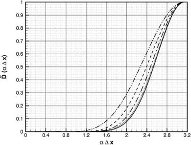
Figure 7.10. Damping functions corresponding to several large damping stencils. – • • —, 7-

point stencil;——- , 9-point stencil;——- , 11-point stencil;……….. , 13-point stencil;——– ,

15-point stencil.

d3 = d-3 = -0.06111106887629 d4 = d-4 = 0.02244708528388 d5 = d-5 = -5.6140376790013E-3 d6 = d-6 = 7.539843954985E-4

A plot of these damping functions is given in Figure 7.10.

EXERCISES [6] [7] 2 [8]

d U d U d [9]U

dt + C 9x V 9×2 ’

The exact damping function on the right side of the equation is

D(aAx) = (a Ax)2.

d2u 9 v 9 u

9×2 9x’ V dx

(a) Discretize v(92u/9×2) directly using a second-order central difference scheme to yield

Подпись: artificial selective damping rather than viscous damping is preferred for eliminating short spurious numerical waves. Consider the linearized Burger’s equation as follows:
Подпись: (1)
Подпись: (2)
Подпись: Now, the viscous terms can be approximated in two ways: directly, as a second derivative, or as two first-order derivatives; i.e.,
Подпись: (3)
Подпись: V
Подпись: V (Ax)2
image97
Подпись: (ui+i 2ui + ui+i)-
Подпись: Find the damping function in wave number space. (b) Discretize (3) using second-order central difference; i.e.,
Подпись: vi =
Подпись: V (Ax)2
Подпись: ui+i ui-i 2Ax image99
image98

Find the damping function in wave number space.

(c) Which approximation is more accurate in terms of reproducing the effect of physical viscosity over the resolved wave range?

(d) Which approximation would help to damp out spurious short waves?

(e) If the objective is to damp out spurious short waves alone with little damping on the long waves, is artificial selective damping better, or are physical viscous terms better?

Aliasing

The fundamental wave number range of a finite difference scheme is – n < a Ax < n (see Figure 2.1). The a Ax versus a Ax curve in the range – n < a Ax < 0 is obtained by an antisymmetric extension of that in the range 0 < a Ax < n. Wave numbers that fall outside this range are underresolved. Their wavelength is less than two mesh spacings. They are aliased back inside the fundamental range. To determine the relationship between the original wave number and the aliased wave number, consider the initial condition (7.4). Let f(x) = Ф (x), where Ф is a Gaussian with a concentration of wave number around a0 ; i. e.,

Подпись: (7.28)t = 0, Ф(x) = e-(ln2)(і)2+ia0x.

Подпись: t = 0, Ф (a) Подпись: b г e 2(n ln2) 2 Подпись: (7.29)

The Fourier transform of Eq. (7.28) is

If b, the half-width of the Gaussian, is large, then Eq. (7.29) confirms that there is an essential concentration of wave number around a = a0.

Let Ax be the mesh size used in a computation. l is the spatial index so that x = lAx. As far as the computation on the mesh is concerned, Eq. (7.28), in the discretized form, is

Ф1 = e-(ln2)(Tr)2+ ia0lAx. (7.30)

It will be assumed that a0Ax > n but less than 2n. Since a0Ax is larger than n, let

Подпись:Подпись: (7.32)a0Ax = n + 5.

But

eia0Axl = ef[2n + (5-n)]l = ei(5-n)l = ei(5-L)x = Є (a0 Ax )x Therefore, the initial condition is the same as

Подпись: (7.33)

t = 0 Ф (x) = e-(ln2)( і )2+i(a0- Ax)x for the computation. In other words, the effective wave number is

Hence, although a0Ax is larger than n, it is aliased back into the fundamental range by a shift of 2n.

As an example, consider the function

image90

image91,image92,image93

(7.35)

image94

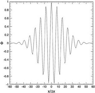
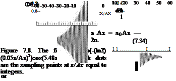
The wave number of this function concentrates around a0Ax = ±5.48. This is outside the fundamental range. For computation on the mesh, the effective wave number, according to Eq. (7.34), is aAx = ±0.803. Figure 7.8 shows the original function (7.35), with wave number concentrates around a0Ax = ±5.48. The black dots in the figure are sampling points. From the finite difference computation point of view, only the sampling points matter. Figure 7.9 shows the function representing the sampling points. This function is the same as

This function has a low wave number of aAx = ±0.803 and lies inside the fundamental range of wave numbers.