Category Dynamics of Flight

The Use of Tabs

TRIM TABS

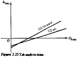
In order to fly at a given speed, or CL, it has been shown in Sec. 2.4 that a certain ele­vator angle Setnm is required. When this differs from the free-floating angle <5efree, a force is required to hold the elevator. When flying for long periods at a constant speed, it is very fatiguing for the pilot to maintain such a force. The trim tabs are used to relieve the pilot of this load by causing <5(,tnm and 8t, lm to coincide. The trim- tab angle required is calculated below.

When Che and Cm are both zero, the tab angle is obtained from (2.5,2) as

Подпись: (2.7,1)1

Jy (Cfieo CheJXtrim "h ^2^e, rim)

Подпись: ^ trim Подпись: 1 b3 The Use of Tabs The Use of Tabs Подпись: (CheaCmSe b2cma)

On substituting from (2.4,13) (which implies neglecting ЭСш/Эб(), we get

which is linear in C/irim for constant h, as shown in Fig. 2.25. The dependence on h is simple, since from (2.6,11) we find that

(CheCmSe – b2CmJ = —a’b2(h – K)

The Use of Tabs The Use of Tabs The Use of Tabs Подпись: (2.7,2)

and hence

Подпись: Figure 2.25 Tab angle to trim.

This result applies to both tailed and tailless aircraft, provided only that the appropri­ate values of the coefficients are used. It should be realized, of course, in reference to Fig. 2.25, that each different CUr. m in a real flight situation corresponds to a different set of values of M, pV2, and C7, so that in general the coefficients of (2.7,2) vary with CL, and the graphs will depart from straight lines.

The Use of Tabs The Use of Tabs Подпись: (2.7,3)

Equation (2.7,2) shows that the slope of the 5,trira vs CLtrim curve is proportional to the control-free static margin. When the coefficients are constants, we have

The similarity between (2.7,3) and (2.4,13c) is noteworthy, that is the trim-tab slope bears the same relation to the control-free NP as the elevator angle slope does to the control-fixed NP. It follows that flight determination of h’n from measurements of d8hr. JdCUt. m is possible subject to the same restrictions as discussed in relation to the measurement of h„ in Sec. 2.4.

OTHER USES

Tabs are used for purposes other than trimming, especially for manually actuated controls. Three of the main types are as follows:

Geared Tabs. Tabs connected to the main surface by a mechanical linkage that causes the tab to deflect automatically when the main surface is deflected, but in the opposite direction. The hinge moment produced by the tab then assists the rotation of the main surface. These have the effect of reducing the b2 of the surface.

Spring Tabs. Tabs connected to the main surface by an elastic element. The design is such that the deflection of the tab depends on the dynamic pressure in a way that mitigates the effect of the speed-squared law on the control force.

Servo Tabs. An arrangement in which the pilot controls the tab directly through a mechanical linkage. It is then the tab, not the pilot, that provides the hinge moment needed to rotate the main surface.

Both spring tabs and servo tabs are effective devices for reducing control forces on large high-speed airplanes. However, both add an additional degree of freedom to the control system dynamics, and this is a potential source of trouble due to vibration or flutter.

For further details of how these tabs function, see Etkin (1972).

TAILED AIRCRAFT

CmSe is given by (2.4,8), so (2.6,11) becomes for this case

(* – h’J = V(h – K) – ^ cLSe(h – KJ + ^

CheJ-^Ls, ‘-‘he,, —

— 7—- K* 1 + ~ a. V,

, ae bx ( де / St __

K – h – – v v, 1 – d -<*■-T+ ^

TAILED AIRCRAFT
Using (2.6,4b) this becomes

The difference (h’n — h) is called the control-free static margin, K’n. When representa­tive numerical values are used in (2.6,13) one finds that hn – h’n may be typically about 0.08. This represents a substantial forward movement of the NP, with conse­quent reduction of static margin, pitch stiffness, and stability.

ELEVATOR-FREE NEUTRAL POINT

It is evident from the preceding comment that the NP of a tailed aircraft when the el­evator is free is given by (2.3,23) as

ELEVATOR-FREE NEUTRAL POINT(2.6,10)

Alternatively, we can derive the NP location from (2.6,5b), for we know from (2.3,5) that

ELEVATOR-FREE NEUTRAL POINT

ELEVATOR-FREE NEUTRAL POINT Подпись: Ф) Подпись: (2.6,11)

(a)

Since CmSe is of different form for the two main types of aircraft, we proceed sepa­rately below.

FREE-ELEVATOR FACTOR

When the elevator is free, the lift-curve slope is given by (2.6,4b), that is,

FREE-ELEVATOR FACTOR(2.6,6)

The factor in parentheses is the free elevator factor, and normally has a value less than unity. When the elevator is part of the tail, the floating angle can be related to a„ viz for b0 = 0

Подпись: or Подпись: 1 Подпись: (2.6,7)

Cht, = b{a, + b28„tm: + b38, = 0

and the tail lift coefficient is

Подпись:(2.6,8)

FREE-ELEVATOR FACTOR

The effective lift-curve slope is

Influence of a Free Elevator on Lift and Moment

In Sec. 2.3 we have dealt with the pitch stiffness of an airplane the controls of which are fixed in position. Even with a completely rigid structure, which never exists, a manually operated control cannot be regarded as fixed. A human pilot is incapable of supplying an ideal rigid constraint. When irreversible power controls are fitted, how­ever, the stick-fixed condition is closely approximated. A characteristic of interest from the point of view of handling qualities is the stability of the airplane when the elevator is completely free to rotate about its hinge under the influence of the aerody­namic pressures that act upon it. Normally, the stability in the control-free condition is less than with fixed controls. It is desirable that this difference should be small. Since friction is always present in the control system, the free control is never real­ized in practice either. However, the two ideal conditions, free control and fixed con­trol, represent the possible extremes.

When the control is free, then Che = 0, so that from (2.5,2)

1

Ce – ~ T~ (C0 + C« + b38,) 02

(2.6,1)

The typical upward deflection of a free-elevator on a tail is shown corresponding lift and moment are

in Fig. 2.24. The

Cfree = C, a + QsAf™

Cf„e = C0 + Cma + cms8efm

(2.6,2)

After substituting (2.6,1) into (2.6,2), we get

Cfree = Co + C, Jot ~ Co С„а

(a)

(2.6,3)

Ф)

where Clo = – % (Cheo + b38t)

t ^ CLsChea

Cl — Cr 0/ ,

" La b2

(a)

(2.6,4)

Ф)

Co = Со г (c„ + m,)

Стя che

/-% nCa

m“ – m“ b2

(a)

(2.6,5)

(b)

Influence of a Free Elevator on Lift and Moment

When due consideration is given to the usual signs of the coefficients in these equa­tions, we see that the two important gradients CLa and Cma are reduced in absolute

magnitude when the control is released. This leads, broadly speaking, to a reduction of stability.

The Control Hinge Moment

To rotate any of the aerodynamic control surfaces, elevator, aileron, or rudder, about its hinge, it is necessary to apply a force to it to overcome the aerodynamic pressures that resist the motion. This force may be supplied entirely by a human pilot through a mechanical system of cables, pulleys, rods, and levers; it may be provided partly by a powered actuator; or the pilot may be altogether mechanically disconnected from the control surface (“fly-by-wire” or “fly-by-light”). In any case, the force that has to be applied to the control surface must be known with precision if the control system that connects the primary controls in the cockpit to the aerodynamic surface is to be de­signed correctly. The range of control system options is so great that it is not feasible in this text to present a comprehensive coverage of them. We have therefore limited ourselves in this and the following chapter to some material related to elevator con­trol forces when the human pilot supplies all of the actuation, or when a power assist relieves the pilot of a fixed fraction of the force required. This treatment necessarily begins with a discussion of the aerodynamics; that is, of the aerodynamic hinge mo­ment.

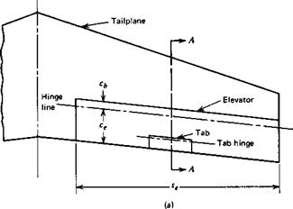
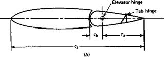
The aerodynamic forces on any control surface produce a moment about the hinge. Figure 2.22 shows a typical tail surface incorporating an elevator with a tab. The tab usually exerts a negligible effect on the lift of the aerodynamic surface to which it is attached, although its influence on the hinge moment is large.

The Control Hinge Moment

The Control Hinge Moment

Figure 2.22 Elevator and tab geometry, (a) Plan view. (b) Section A—A.

The coefficient of elevator hinge moment is defined by

Подпись: Che ~He

l2pV2Sece

Here He is the moment, about the elevator hinge line, of the aerodynamic forces on the elevator and tab, Se is the area of that portion of the elevator and tab that lies aft of the elevator hinge line, and ce is a mean chord of the same portion of the elevator and tab. Sometimes ce is taken to be the geometric mean value, that is, ce = SJ2se, and other times it is the root-mean square of ce. The taper of elevators is usually slight, and the difference between the two values is generally small. The reader is cautioned to note which definition is employed when using reports on experimental measure­ments of Che-

Of all the aerodynamic parameters required in stability and control analysis, the hinge-moment coefficients are most difficult to determine with precision. A large number of geometrical parameters influence these coefficients, and the range of de­sign configurations is wide. Scale effects tend to be larger than for many other pa­rameters, owing to the sensitivity of the hinge moment to the state of the boundary layer at the trailing edge. Two-dimensional airfoil theory shows that the hinge mo­ment of simple flap controls is linear with angle of attack and control angle in both subsonic and supersonic flow.

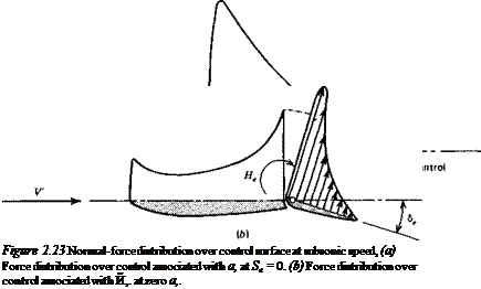
The normal-force distributions typical of subsonic flow associated with changes in a and 8e are shown qualitatively in Fig. 2.23. The force acting on the movable flap has a moment about the hinge that is quite sensitive to its location. Ordinarily the hinge moments in both cases (a) and (b) shown are negative.

In many practical cases it is a satisfactory engineering approximation to assume that for finite surfaces Che is a linear function of as, 8e, and 8r The reader should note however that there are important exceptions in which strong nonlinearities are present.

Подпись: where The Control Hinge Moment Подпись: (2.5,1)

We assume therefore that Che is linear, as follows,

a, is the angle of attack of the surface to which the control is attached (wing or tail), and 8, is the angle of deflection of the tab (positive down). The determination of the hinge moment then resolves itself into the determination of b0, bu b2, and b3. The geometrical variables that enter are elevator chord ratio cjc„ balance ratio cjce, nose shape, hinge location, gap, trailing-edge angle, and planform. When a set-back hinge is used, some of the pressure acts ahead of the hinge, and the hinge moment is less than that of a simple flap with a hinge at its leading edge. The force that the control system must exert to hold the elevator at the desired angle is in direct proportion to the hinge moment.

We shall find it convenient subsequently to have an equation like (2.5,1) with a instead of as. For tailless aircraft, a, is equal to a, but for aircraft with tails, as = a,. Let us write for both types

Che ~ Che о + Chea + b2Se + b3S, (2.5,2)

where for tailless aircraft Chen — b0, Chea = bt. For aircraft with tails, the relation be­tween a and a, is derived from (2.3,12) and (2.3,19), that is,

Подпись: де 1 - - (e° + if) Подпись: (2.5,3)

The Control Hinge Moment

a. S, / де

1——- — (1 – —

a S da

The Control Hinge Moment Подпись: a, S, a 5 Подпись: Эе да The Control Hinge Moment Подпись: (2.5,4)

whence it follows that for tailed aircraft, with symmetrical airfoil sections in the tail, for which b0 = 0,

The Control Hinge Moment

FLIGHT DETERMINATION OF A„ AND hs

Подпись: or FLIGHT DETERMINATION OF A„ AND hs Подпись: (2.4.28) (2.4.29)

For the general case, (2.3,5) suggests that the measurement of hn requires the mea­surement of Cma and CLa. Flight measurements of aerodynamic derivatives such as these can be made by dynamic techniques. However, in the simpler case when the complications presented by propulsive, compressibility, or aeroelastic effects are ab­sent, then the relations implicit in Figs. 2.18 and 2.19 lead to a means of finding h„ from the elevator trim curves. In that case all the coefficients of (2.4,13) are con­stants, and

Подпись: Figure 2.21 Determination of stick-fixed neutral point from flight test.

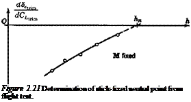
Thus measurements of the slope of Setr. m vs. CLmm at various CG positions produce a curve like that of Fig. 2.21, in which the intercept on the h axis is the required NR When speed effects are present, it is clear from (2.4,27) that a plot of (d8etrjJdV)s against h will determine hs as the point where the curve crosses the h axis.

ELEVATOR ANGLE TO TRIM

The trim condition is Cm = 0, whence from (2.4,1 d)

Подпись: (2.4,10)„ CJa)

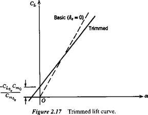
The trimmed lift-curve slope is seen to be less than CLa by an amount that depends on Cma, i. e., on the static margin, and that vanishes when h = hn. The difference is only a few percent for tailed airplanes at normal CG position, but may be appreciable for tailless vehicles because of their larger CLs. The relation between the basic and trimmed lift curves is shown in Fig. 2.17.

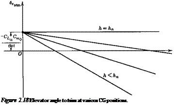
Equation (2.4,13&) is plotted on Fig. 2.18, showing how Setrim varies with CUnm and CG position when the aerodynamic coefficients are constant.

VARIATION OF 5etrlm WITH SPEED

When, in the absence of compressibility, aeroelastic effects, and propulsive system effects, the aerodynamic coefficients of (2.4,13) are constant, the variation of <5£,tnm with speed is simple. Then Seuim is a unique function of CLcr. m for each CG position. Since CUr. m is in turn fixed by the equivalent airspeed,[7] for horizontal flight

Подпись: (2.4,17)

ELEVATOR ANGLE TO TRIM

W

3ft)

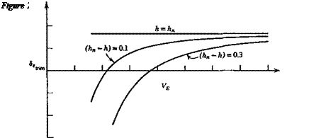
then <5,,mn becomes a unique function of VE. The form of the curves is shown in Fig. 2.19 for representative values of the coefficients.

Подпись: Figure 2.18 Elevator angle to trim at various CG positions.

The variation of 8f, uim with C/tnm or speed shown on Figs. 2.18 and 2.19 is the normal and desirable one. For any CG position, an increase in trim speed from any initial value to a larger one requires a downward deflection of the elevator (a forward

movement of the pilot’s control). The “gradient” of the movement d8ettiJdVE is seen to decrease with rearward movement of the CG until it vanishes altogether at the NP. In this condition the pilot in effect has no control over trim speed, and control of the vehicle becomes very difficult. For even more rearward positions of the CG the gra­dient reverses, and the controllability deteriorates still further.

When the aerodynamic coefficients vary with speed, the above simple analysis must be extended. In order to be still more general, we shall in the following explic­itly include propulsive effects as well, by means of the parameter 8p, which stands for the state of the pilot’s propulsion control (e. g., throttle position). 8p = constant there­fore denotes fixed-throttle and, of course, for horizontal flight at varying speed, 8p must be a function of V that is compatible with T = D. For angles of climb or descent in the normal range of conventional airplanes L = W is a reasonable approximation, and we adopt it in the following. When nonhorizontal flight is thus included, 8P be­comes an independent variable, with the angle of climb у then becoming a function of 8p, V, and altitude.

The two basic conditions then, for trimmed steady flight on a straight line are

Подпись:Подпись: (2.4,19)

ELEVATOR ANGLE TO TRIM

cm = o

L = CLpV2S = W and in accordance with the postulates made above, we write

Cm = Cm(a, V, 8e, 8p) CL = CL(a, V, 8e, 8P)

ELEVATOR ANGLE TO TRIM ELEVATOR ANGLE TO TRIM

Now let ( )e denote one state that satisfies (2,4,18) and consider a small change from it, denoted by differentials, to another such state. From (2.4,18) we get, for p = const,

There are two possibilities, 8p constant and 8p variable. In the first case (fixed throt­tle), d8p = 0 and

ELEVATOR ANGLE TO TRIM(2.4,24)

It will be shown in Chap. 6 that the vanishing of this quantity is a true criterion of stability, that is it must be >0 for a stable airplane. In the second case, for example exactly horizontal flight, 8p = Sp(V) and the 8p term on the right-hand side of (2.4,23) remains. For such cases the gradient (d8euJdV) is not necessarily related to stability. For purposes of calculating the propulsion contributions, the terms CLs d8p and Cms d8p in (2.4,23) would be evaluated as dCLp and dCmp [see the notation of (2.3,1)]. These contributions to the lift and moment are discussed in Sec. 3.4.

The derivatives Q, and Cmv may be quite large owing to slipstream effects on STOL airplanes, aeroelastic effects, or Mach number effects near transonic speeds. These variations with M can result in reversal of the slope of 8etrtm as illustrated on Fig. 2.20. The negative slope at A, according to the stability criterion referred to above, indicates that the airplane is unstable at A. This can be seen as follows. Let the airplane be in equilibrium flight at the point A, and be subsequently perturbed so that its speed increases to that of В with no change in a or 8e. Now at В the elevator angle is too positive for trim: that is there is an unbalanced nose-down moment on the air­plane. This puts the airplane into a dive and increases its speed still further. The speed will continue to increase until point C is reached, when the 8e is again the correct value for trim, but here the slope is positive and there is no tendency for the speed to change any further.

Подпись: VПодпись:ELEVATOR ANGLE TO TRIM

ELEVATOR ANGLE TO TRIM

О

STATIC STABILITY LIMIT, hs

The critical CG position for zero elevator trim slope (i. e. for stability) can be found by setting (2.4,24) equal to zero. Recalling that Cma – CLa(h – hn), this yields

h-h"-c^icZ=° <2«5>

or h = hs

C

where K = hn+ — (2.4,26)

^Lv ^Le

Depending on the sign of Cmv, hs may be greater or less than hn. In terms of hs, (2.4,24) can be rewritten as

<2Л27)

(h — hs) is the “stability margin,” which may be greater or less than the static margin.

Longitudinal Control

In this section we discuss the longitudinal control of the vehicle from a static point of view. That is, we concern ourselves with how the equilibrium state of steady rectilin­ear flight is governed by the available controls. Basically there are two kinds of changes that can be made by the pilot or automatic control system—a change of propulsive thrust, or a change of configuration. Included in the latter are the opera­tion of aerodynamic controls—elevators, wing flaps, spoilers, and horizontal tail ro­tation. Since the equilibrium state is dominated by the requirement Cm = 0, the most powerful controls are those that have the greatest effect on Cm.

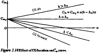
Figure 2.14 shows that another theoretically possible way of changing the trim condition is to move the CG, which changes the value of a at which Cm = 0. Moving it forward reduces the trim a or CL, and hence produces an increase in the trim speed. This method was actually used by Lilienthal, a pioneer of aviation, in gliding flights during 1891/1896, in which he shifted his body to move the CG. It has the inherent disadvantage, apart from practical difficulties, of changing Cma at the same time, re­ducing the pitch stiffness and hence stability, when the trim speed is reduced.

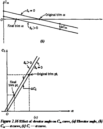
The longitudinal control now generally used is aerodynamic. A variable pitching moment is provided by moving the elevator, which may be all or part of the tail, or a trailing-edge flap in a tailless design. Deflection of the elevator through an angle 8e produces increments in both the Cm and CL of the airplane. The AC, caused by the el­evator of aircraft with tails is small enough to be neglected for many purposes. This is not so for tailless aircraft, where the ACL due to elevators is usually significant. We shall assume that the lift and moment increments for both kinds of airplane are linear in 8e, which is a fair representation of the characteristics of typical controls at high Reynolds number. Therefore,

A CL = CLs8e (a)

CL = CL(a) + CLs8e (b)

ACm = Cms8e (c) ‘ ’

and Cm = Cm(a) + Cms8e (d)

where CL% = dCJd8e, C,„n> = dCJd8e, and CL(a), Cm(a) are the “basic” lift and mo­ment when 8e = 0. The usual convention is to take down elevator as positive (Fig. 2.16a). This leads to positive CLs and negative Cms/ The deflection of the elevator

34 Chapter 2. Static Stability and Control—Part 1

^-Horizontal tail

c—1

Подпись: Figure 2.16 Effect of elevator angle on Cm curve, (a) Elevator angle, (b) Cm — a curve, (с) C, — a curve.

(a) ^

through a constant positive angle then shifts the Cm-a curve downward, without change of slope (Fig. 2.16b). At the same time the zero-lift angle of the airplane is slightly changed (Fig. 2.16c).

In the case of linear lift and moment, we have

EFFECT OF LINEAR LIFT AND MOMENT ON NEUTRAL POINT

When the forces and moments on the wing, body, tail, and propulsive system are lin­ear in a, as may be near enough the case in reality, some additional useful relations can be obtained. We then have

CLwb = awbawb (2.3,9)

Q, = ata, (2.3,10)

dCm

and Cmp = Cm0p + • a (2.3,11)

If Cmwb is linear in CLwh, it can be shown (see exercise 2.3) that Cmac^ does not vary with CLwb, i. e. that a true mean aerodynamic center exists. Figure 2.11 shows that the tail angle of attack is

a, = awh ~ i, ~ e (2.3,12)

and hence CL, = a,{awh — i, — e) (2.3,13)

The downwash e can usually be adequately approximated by

є = e0+ awb (2.3,14)

da

The downwash e0 at awh = 0 results from the induced velocity field of the body and from wing twist; the latter produces a vortex wake and downwash field even at zero total lift. The constant derivative de/da occurs because the main contribution to the downwash at the tail comes from the wing trailing vortex wake, the strength of which is, in the linear case, proportional to CL.

EFFECT OF LINEAR LIFT AND MOMENT ON NEUTRAL POINT EFFECT OF LINEAR LIFT AND MOMENT ON NEUTRAL POINT

The tail lift coefficient then is

Подпись: (b) (2.3,16) (c) or CL = {CL) о + aawh

Подпись: where Подпись: (Q)0 = Подпись: «о) Подпись: (2.3,17)
EFFECT OF LINEAR LIFT AND MOMENT ON NEUTRAL POINT

or since awh and a differ by a constant
CL = aa

EFFECT OF LINEAR LIFT AND MOMENT ON NEUTRAL POINT Подпись: (2.3,18)
EFFECT OF LINEAR LIFT AND MOMENT ON NEUTRAL POINT

is the coefficient of the lift on the tail when awb = 0;

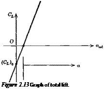
Подпись: Figure 2.13 Graph of total lift.

is the lift-curve slope of the whole configuration; and a is the angle of attack of the zero-lift line of the whole configuration (see Fig. 2.13). Note that, since i, is positive,

then (CL)о is negative. The difference between a and awb is found by equating (2.3,16b and c) to be

into (2.3,1) the fol­lowing results can be obtained after some algebraic reduction:

Note that since Сшо is the pitching moment at zero awb, not at zero total lift, its value depends on h (via V„), whereas Cmo, being the moment at zero total lift, represents a couple and is hence independent of CG position. All the above relations apply to tail­less aircraft by putting VH = 0. Another useful relation comes from integrating

(2.3,5) , i. e.

Cm = Cmo + C/(h – h„) (a)

Cm = Cmo + aa(h – hn) (b) (2.3,25)

or Cma = a(h – hn) (c)

Подпись: Figure 2.14 Effect of CG location on Cm curve.

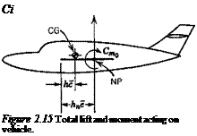
Figure 2.14 shows the linear Cm vs. a relation, and Fig. 2.15 shows the resultant sys­tem of lift and moment that corresponds to (2.3,25), that is a force CL and a couple

Подпись: Ci Figure 2.15 Total lift and moment acting on vehicle.

Cmo at the NP. Figure 2.15 is a very important result that the student should fix in his mind.