Category FLIGHT MECHANICS MODELING and ANALYSIS

STABILITY/CONTROL AUGMENTATION STRATEGIES

An FCS can have various roles to play: (1) automatic pilot controller—autopilot,

(2) basic stability augmentation, (3) guidance control loop, and (4) FBW/FCS for high-performance fighter or even transport aircraft (like AIRBUS 320). In any case, control deflection would be applied, which is proportional to the deviation of the aircraft, say, in the attitude from the reference value (Figure 8.1). New situations and developments paved the way for intense research in flight mechanics and control [3]: (1) increased wing loading, (2) mass concentration in the slender fuselages,

(3) swept/delta wing aircraft, (4) hydraulic powered controls, and (5) introduction of turbojet engines. These basic changes in the design of aircraft were required to expand the flight envelope of the aircraft and to enhance the performance of the aircraft [3]. This resulted in deficiency in stability and control characteristics of the aircraft, which further gave impetus to the design and development of sophisti­cated FBW/FCS. In order to handle the large hinge moments of the control surfaces, hydraulic and related control systems came into use, which increasingly ‘‘distanced’’ the pilot from the ‘‘feel’’ of the aerodynamic forces acting on the control surfaces. This further introduced the use of the artificial feel system to aid the pilot in performing the control task. A modern high-performance fighter aircraft would have full authority FBS/FCS, which would cater not only to the basic stabilization task but also to many tasks that allow for care-free maneuvering of the aircraft and provide overall best aerodynamic efficiency. Any FCS would be based on some control strategies that are described next [3-5].

With three-axis attitude stabilization, a feasible mechanization of flight control would be attitude rate and attitude stabilization—attitude hold—when no command is given. This leads to ‘‘rate command/attitude hold’’ system and the pilot’s task of stabilization of the aircraft is either eliminated or drastically reduced. A control system strategy based on U or a and 8e stabilizes the angular motion of an aircraft. In (U, 8e) strategy, the U is kept constant and the inherently unstable aircraft is made stable. The attitude response of the aircraft due to gust inputs can be reduced.

вс ве Se

image145

FIGURE 8.1 Attitude stabilization control system.

This helps reduce the pilot’s workload. In the case of the control strategy based on (a, 8e), the airflow direction relative to the aircraft is maintained constant. However, the pilot cannot get the feel of the AOA, since it cannot be visualized from the out-of­window view. Another demerit is that AOA measurements could often be inaccurate. The alternative control strategy based on (nz, 8e) would maintain the load factor constant. Over and above the foregoing control strategies, a system based on u and engine thrust can be used to ‘‘stabilize’’ the airspeed. This strategy, however, has a demerit during takeoff and initial climb phases because maximum thrust is demanded. Yet another control strategy is to use a direct-lift (aerodynamic) control surface to effect changes in the flight path angle. The (g, 8e) TF is given by

With a small value of na, there would be a large lag in the variation of g after the change in pitch attitude has occurred. Also, the small value of na requires large AOA changes and hence large pitch angle changes. In the above situation limited use of the direct-lift control strategy would be useful due to increase in drag, thereby restricting the use in the approach and landing phases of the flight.

AFCS would mainly consist of sensors, output devices, and onboard digital computers. The sensors measure the relevant parameters and signals and transmit these to the computers. The output devices convert the computed signals to actuator commands. The onboard computers’ functions are [4] (1) amplification of the signal levels, (2) integration, (3) differentiation, and (4) limiting, shaping, and programming. The control laws: the control filters, transfer functions, and gain scheduling algorithms are implemented on these computers. In general AFCS would be of various types: (1) rate damping systems, (2) control augmentation systems, (3) autopilots, and (4) model following control systems. These systems could be (1) duplex, (2) cross-coupled feedback, (3) triplex system, or (4) quadruplex system.

Example 8.1

The state-space model of the short period dynamics of a light transport aircraft is given as

Подпись:W — ZwW + (u0 + Zq)q + Z8e 8

q — MwW + Mqq + M8e 8e

Assume there is instability in pitch dynamics and hence the Mw has positive numerical value. Stabilize the system with appropriate feedback from the vertical speed. Give new state-space equations.

Solution

Let the feedback gain be K units. Then one can augment the control surface input as 8e — 8p + Kw, where 8p is the pilot’s stick command input. Substituting this for the control surface in the open loop state-space equations we get

w — Zww + (uo + Zq)q + Zse (Sp + Kw) q — Mww + Mqq + Mse (Sp + Kw)

After simplification we get


(8.3)


w — (Zw + ZdeK)W + (uo + Zq)q + ZSe Sp q — (Mw + MseK)w + Mqq + MSe Sp


(8.4)


Since the dimensional moment derivative is augmented with an extra term with K as the feedback gain factor, by choosing an appropriate value for K one can make the system stable. Since the control effectiveness derivative has normally a negative sign, a small value of K might be sufficient to stabilize the system.


Example 8.2

Let the state-space model for a dynamic system be given as


x(k + 1) — Fkx(k) + Bu(k) y(k) — Hx(k)


(8.5)


Assume that the system is unstable and the responses/signals are increasing without bound. Use an appropriate transformation method on the unstable data and appropri­ately reformulate the state-space equations.


Solution

Assume that a suitable parameter ‘‘d’ is available, then the states, input, and output data can be transformed to stable data. The new transformed data would be


x(k) — e dkx(k)

x(k) — e~dky(k), u(k) — e~dku(k) The above equations can be written as

x(k) — e+dkx(k)

y(k) — e+dky(k), u(k) — e+dk u(k)


(8.6)


(8.7)


Substituting the above expressions into the state-space equation, we obtain the expres­sions for the stabilized data/system:


e+d(k+1)x(k + 1) — Fke+dkx(k) + Be+dk u(k) e+dky(k) — He+dkX(k)


(8.8)


Simplifying we get


edx(k + 1) — Fkx(k) + Bu(k) xy(k) — Hxx(k)


Finally, in terms of the transformed data the state-space equations would be

u(k + 1) — e dFku(k) + e dBu(k) U(k) — HU(k)

Подпись:U(k + 1) — FkdU(k) + BdU(k)

U(k) — HU(k)

We see that the elements of the transition matrix and the control input vector/matrix are changed. Thus, by appropriately choosing the value of d the system equations can be stabilized. The growing data of the unstable system can be de-trended and used in system identification/parameter schemes to estimate the parameters of the inherently unstable system (Chapter 9).

REQUIREMENTS OF FLIGHT CONTROL

What is true of general control systems (Appendix C) is also applicable to automatic flight-control system (AFCS) for an aircraft. The need of aircraft to fly in clouds and fog and to reduce the pilot workload during flight operation paved the way for the devel­opment of devices to stabilize the aircraft by artificial means [3]. In the case of an FBW (fly-by-wire) aircraft, the artificial stabilization is required because the aircraft is inher­ently designed to have static instability for performance gains. The automatic maneuver envelope protection takes place due to the limits provided (in the computer) on the responses. Any reasonably desired limit on altitudes, speed, AOA, and “g” force can be provided. The relaxed static stability (RSS) allows to plan smaller tail surfaces on such FBW aircraft and hence weight saving could be up to 10%.

Confluence of Aero-Control-Formative Years

Period

Aircraft Dynamics Theory

Feedback Control of Aircraft

Feedback Control Theory

1980

Gyroscope stabilization (Maxim); torpedo course control (Obry)

1990

Study of phugoids (Lanchester); small perturbation theory (Bryan and Williams)

1910

Measurements of derivatives and calculation of motions (Bairstow and Jones); the methods introduced in the United States (Hunskar)

Demo of two-axis aircraft stabilizer/aerial torpedo (Evan and Lawrence Sperry)

1920

Measurements/calculations of derivatives (Glauert, Bryant, Irving, and Cowley)

Full-scale flight tests confirm the theory

Study of aircraft under continuous control (Gates, Gamer)

1930

The status of theory surveyed (B. M. Jones)

RAE-Mark IV-Siemens automatic pilot/development of pneumatic-hydraulic A2-Wiley postflight

Stability of feedback amplifier studied (Nyquist) Logarithmic plots, sensitivity (Bode)

1940

For a variety of aircraft and conditions, the advances in calculations made

Study of response under control

Rudder control, missile development (Germany), all-electric and maneuvering automatic pilots, flight of “Robert R. Lee”

The techniques applied to servomechanisms (Harris), thesis by Hall

The new texts

Frequency methods (Greenberg, Seacord, and others)

Root locus method (Evans)

1950

_

TABLE 8.1

Lecture by Bollay Volumes by the BuAer-Northrop Improvements in understanding of flight control

Подпись: 230 Flight Mechanics Modeling and AnalysisSource: McRuer, D. and Graham, D., J. Guid., Control, Dynam., 27, 161, 2004.

FCS aids a pilot in controlling the aircraft safely and effectively throughout the entire flight envelope (Figure 7.1). Besides providing the basic stability, if needed, AFCS in particular provides good handling qualities (Chapter 10). However, funda­mentally AFCS provides the required stability and improved damping to the basic airframe, if these are inherently poor or insufficient. This aspect could be realized either by an autopilot or a limited authority command and stability augmentation system (SAS).

Since the response of AFCS would be much more rapid than that of a human pilot, the effect of the disturbance would not reach sizeable magnitude. The pilot can detect a change in the pitch altitude of 1° in 0.3 s and there would be a further delay of 0.5 s by the pilot in his decision making on the amount of the correction required to be applied [4]. However, the autopilot can detect the disturbance of 0.1° in 0.05 s or even less and then apply an input to overcome the disturbance in 0.1 s, thus gaining considerable advantage in the control response. This also means that less disturbance is seen by the aircraft.

In some cases AFCS could be a full authority FBW/FCS. Modern high- performance aircraft are designed to have RSS or are inherently unstable in longi­tudinal axis. The RSS concept means that the CG of the airframe is more aft than the conventional designs. If the CG is aft of the neutral point (Appendix A), then the basic aircraft would be statically unstable. This allows reduction in the area of the horizontal tail surface. Weight and trim drag will be reduced. Certain advantages can be gained by this type of design. The major reason for this approach is that a more favorable aerodynamic force balance is achieved than the conventional stable airframe configuration. The wing lift is aided by the control surface lift contribution and for a given AOA, there is higher lift and reduced drag (for a given lift) for the inherently unstable/RSS airframe configuration. In conventional aircraft, the balance of momentum is achieved by downward lift of the elevator. This has a negative effect on the total lift. Whereas in the case of the unstable configuration the moment balance is achieved with the upward lift of the elevator and hence the total lift of the aircraft is increased. Other merits for such a design are as follows [5]: (1) about 10% to 15% gain (depending on the configuration) in the maneuver margin (Appen­dix A), (2) reduction in fuel consumption, and (3) increased climb rate. Since the inherently unstable aircraft cannot fly, it needs artificial stabilization. It could have FBW/FCS with either limited or full authority command. Rafale, Gripen, F-22, and Eurofighter Typhoon aircraft are designed to be unstable.

In particular, FBW/FCS-related control laws have several major functions to perform: (1) SAS for excellent HQs and aircraft maneuverability, (2) automatic speed and flight trajectory control (via autopilot), thereby reducing pilot workload, (3) safe operability in all weather situations, (4) effective gust load alleviation, (5) an extended service life and enhancement of ride qualities, (6) performance optimization, and (7) reconfigurable/restructurable control tasks in the event of sensor/actuator faults or control surface damages.

From the point of view of ‘‘flight path,’’ the resulting control problem is to generate adequate deflection of aerodynamic control surfaces or changes in power or thrust to maintain the shape of the flight path and the velocity along this path. In all transport and most other aircraft, autopilot is used to reduce the pilots’
workload. The autopilot is used to control the motion of the vehicle in pitch, yaw, and roll axes in order to follow the required trajectory. The main aim is to ensure the stability of the vehicle in the presence of disturbances/forces/moments caused by various sources while maintaining structural integrity. While the autopilot strives to achieve the desired instantaneous values, the guidance system aims at achieving the desired end-of-the flight conditions. The autopilot is the inner control loop, whereas the navigation/guidance is the outer loop. Normally, the BW of the vehicle control loop is 0.2 to 0.6 Hz and that for the navigation/guidance is 0.02 to 0.04 Hz. The guidance system employs the navigation system as sensors to detect the instantan­eous velocity/position of the vehicle and generates the guidance commands to reach the desired conditions. Navigation is based on the high-precision measurements of acceleration and high speed/accuracy of the required computations. The autopilot consists of precision angular and angular rate sensors. All the autopilot modes help the pilot in effective maneuvers mostly with hands off. The autopilot could have several types of modes as shown in Table 8.2 [5].

Due to the fact that some additional information/data are required to per – form/conduct certain coupled/integrated modes, the interaction of autopilot with IMU and air data system would be definitely required. The autopilot types are: (1) roll (bank angle position) autopilot (holds the aircraft in level position), (2) rate controller (stabilizes the aircraft), (3) heading select and hold autopilot (keeps the course of the aircraft), (4) vertical speed, (5) airspeed select and hold, (6) Mach number hold, (7) pitch altitude hold, (8) altitude select and hold, (9) glide slope, (10) approach/flare, (11) localizer, (12) runway align, and (14) flight path angle controller (helps in climbs). Accelerations autopilots are generally used in missiles and altitude hold autopilots alleviate pilot workload. A brief description of a few control aspects is given here [4].

Подпись:

Подпись: TABLE 8.2 Autopilot Modes Basic Modes Pitch and roll attitude hold Heading hold
Подпись: Coupled Modes Heading select/acquire Altitude hold/select/acquire Mach hold Flight path/track/hold/acquire

Altitude hold: The pitch attitude sensing element detects any change in the aircraft attitude. This change will be compensated by appropriate feedback law. However, changes in vertical displacement cannot be detected by an attitude sensor. Therefore, for automatic leveling off at any desired altitude, an altitude hold function is required. The proper sensor is based on a pressure transducer, and it senses a change in altitude as a change in (static) pressure. Correspondingly, the elevator servo actuator is operated to apply elevator control to restore the aircraft to the selected altitude. The altitude hold signal can be obtained from an inertial reference

system. This signal is augmented with a barometric pressure correlated altitude signal (from the altitude sensor) in an air data computer that interfaces with the FCS.

Airspeed hold: An airspeed sensor measures the difference between static and dynamic pressures. The speed error signal is applied to the pitch sensor control channel.

Mach hold: The airspeed hold mode is normally used for the low-altitude flights. The Mach hold is used during the high-altitude phase.

Reconfiguration and Fuzzy Control Analysis

8.1 INTRODUCTION

In aerospace engineering studies, the practice of flight control is a systems discipline. Understanding of the feedback systems (Appendix C) approach is vital to understand­ing flight control theory and practice of piloted, remotely piloted, or even autonomous atmospheric vehicles (FBW aircraft, missiles, rotorcraft, UAVs, and MAVs). Even the Wright brothers appreciated the fact that the secret to the control of flight was feedback (it could have been a human as a sensor, an actuator, or a controller!). They recognized that the pilot should be able to operate the controls to stabilize, control, and guide the airplane in the desired way and recognized the need for solving the problem of stability and controllability. In fact, they built their ‘‘flyer’’ as a slightly unstable and control­lable one as an engineering experiment. An interesting confluence of theory and practice of automatic feedback control is depicted in Table 8.1 [1]. Applications of control theory to aerospace (leading to flight control) span four major areas [2]: flight planning, navigation, guidance, and control. In order to build a satisfactory control strategy, adequate models of the dynamic system to be controlled are required. The control strategy is that of the ‘‘feedback’’ from the output variable to the input variable (added to the pilot input command). The main idea is that with the information from the output variable, the input variable is suitably altered so that with the new/composite input, the control system’s (e. g., aircraft’s) response comes as close as possible to the desired output. Some fundamental aspects and concepts of control are highlighted in Appendix C. In this chapter the requirements and some control strategies are highlighted and main aspects of fault modeling, analysis, reconfigur­ation, and fuzzy control are discussed from the modeling and analysis point of view.

Transactions

The signals obtained from the flight maneuvers in ASCII file format can be stored in the data storage device. The FDBM application helps to upload raw or processed data from the storage device and subsystems. The file index-flight number will be the key ID to identify the respective flight/S&C data/parameters. The user interfaces available are status, bounds on the data, bounds on the longitudinal estimation, longitudinal reference values bounds, lateral estimation bounds, lateral reference values bounds, upload files, and delete transactions.

7.9.5.1 Graphs/Reports

Graphs could be plotted with respect to the available flight data to view the acquired/stored signal status. This helps the user decide the scope of values and the type of graph to print. For printing the reports the user can select multiple columns from multiple tables. The user interfaces available under this menu are plot graphs, raw data graphs, processed data graphs, and derivative graphs. Under the report menu, the print reports option is available.

image144

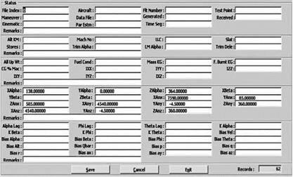
FIGURE 7.14 A typical status screen of the flight database management system SW. 7.9.5.3 User Maintenance

The system administrator can add/modify the users. Users would be provided the privileges based on their roles. The users would have options to change their passwords. The user interfaces available under this menu are add/modify user and change password.

EPILOGUE

Flight testing of any aircraft is a very important activity from the point of view of performance evaluation and certification. The concept of energy management seems to be very interesting in the understanding of various flight test maneuvers. Before performing these maneuvers on the real aircraft, one can carry out the same on flight simulators. The simulator flight data can be studied and analyzed to gain confidence in performing these maneuvers in real flight. Flight database management is of extreme importance due to the vast amount of flight trajectories that could get accumulated. Keeping track of the data and the related information generated via extensive analysis is necessary for successful completion of flight tasks. Only a few aspects of flight testing and DBMS have been covered in this chapter. Flight testing is generally not extensively considered in flight mechanics courses. In addition, open literature in this area is fairly limited.

Brief Description of a Typical Program

A typical program of flight database would help perform the following operations/ tasks: (1) upload the raw flight data and subsequently the processed flight data,

(2) enter/edit the stability and control (S&C) derivatives, (3) plot the required graphs of the flight data, and (4) print results based on the selections made. Typical HW/SW requirement would be (1) latest available PCs, (2) Oracle database server,

(3) Oracle developer suite runtime [22], and (4) and Windows environment.

Menus:

Transactions —to upload raw and processed flight data, to delete the

data, and to add/edit the stability and control derivatives Graphs —different types of plotting options would be available

Reports —different types of report options would be available

User maintenance—option to manage users would be available Help —online help for flight data management

Exit —exiting from the application

The following description is given mainly with respect to the flight database collected from signal receiving devices for the purpose of estimation of aerodynamic (S&C) derivatives and the parameter estimation results thereof. A typical status screen of the flight DBMS is shown in Figure 7.14.

Flight Test Database in Oracle

Here, the development of a typical DBMS using Oracle 8 (there could be other SW/tools possible [17]) is briefly described [16,18-21]. Its client-server architecture

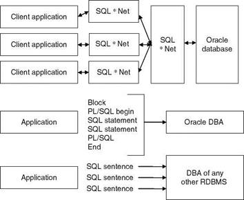
(say, two PCs connected via LAN, local area network) can be used, leading to a multi­user access system with a centralized data bank over LAN. The data can be loaded directly into the database tables from ASCII file. This can be done either manually using an interactive menu or via the Oracle Loader. Also, SQL * Loader can be used for loading the data from a non-Oracle data source to the Oracle database. Oracle 8 is a component of networking computing architecture and this feature reduces the cost. Some features of Oracle 8 are (1) client-server architecture, (2) object/relational technology, (3) concurrent database users, and (4) SQL * Loader/Oracle Loader facil­ity. These features are briefly described next. A communications and code transfer process in a typical DBMS is depicted in Figure 7.13.

Client-server mode: The database system is divided into (1) a client portion or a front end and (2) a server portion or a back end. The client PC is responsible for controlling the user interface. The server PC is the host to the relational database management system. An application program residing on the client PC interfaces with another SW layer known as SQL * Net. The latter is responsible for communicating requests and their results between the application program and the relational database management system. The client PCs directly communicate with the database server.

Concurrent database users: Oracle supports a large number of users at the enterprise level using Net 8, the new version of SQL * Net. The data that are on Windows NT PCs can be accessed by these users.

Object/relational technology: This helps in the design of an object-oriented database. This extends the traditional Oracle relational database management system to include object-oriented concepts and structures.

image143

SQL * Loader or Oracle Loader. The tool can be used to move the data from a non-Oracle standard source into the Oracle database. The data can be loaded from multiple data files and in fixed/delimited formats. The data file containing the actual data and the control file containing the specifications that drive the SQL * Loader session are provided as inputs to the SQL * Loader. The loader reads text files and places the data in the Oracle database based on the instructions in the control file. The control file provides the information related to (1) names of the input data files,

(2) names of the database tables into which the data are to be uploaded, (3) the mode in which the data are to be loaded (like replace, appends, or insert), (4) the correspondence between the data fields and the table columns, and (5) the selection criteria for loading.

A brief note on Oracle 8: It is an object relational database management system. The objects can be defined as reusable SW codes. These codes are location independent and perform a specific task on any application. The client-server concept segregates the processing of an application between two systems. One system (PC) performs all activities related to the database server and the other (client) performs activities that help the user to interact with the application. The front-end/client database applica­tion also interacts with the database by requesting and receiving information from the database server. The client acts as an interface between the user and the database. It also checks for validation against the data entered by the user. The user front-end tools of Oracle are SQL* Plus V 8, Oracle Forms 5.0, and Reports 3.0 and of course the later versions. The back-end server manages the database tables among the multiple clients. These clients concurrently request the server for the same data. The server also maintains the integrity across all client applications. It controls the database access and security requirements.

PL/SQL and FORM: SQL is the natural language of the database administrator. However, it does not have procedural capabilities of looping and branching. It also does not have any conditional checking capabilities. The Oracle has PL/SQL which can be used to create programs for validation and manipulation of table data. It provides the user with all the facilities of a programming environment. PL/SQL closes the gap between database technology and procedural programming languages. It is a development tool and extends the capability of Oracle’s SQL database language. One can insert, delete, update, and retrieve table data. One can use procedural techniques of writing loops and branching to another block of codes. As it is an extension of the SQL, it allows one to use all the SQL data manipulation statements. It also allows curser control operations and transaction processing, as well as logical grouping of SQL sentences and passing them to the database administrator as a single block. The entire block of statements can be sent to the RDBMS engine. PL/SQL can be used in SQL*FORMS, and its procedural capabilities can be used for writing complex triggers that would validate data before they are placed in the tables. The applications in PL/SQL are portable to any computer hardware (HW) and operating system (OS), where Oracle is operational. The Oracle Forms Builder provides GUI to design forms. All objects, properties, and triggers can be selected by clicking on an appropriate icon. The tool comprises (1) Forms Builder, (2) Forms compiler, and (3) Forms Runtime. An application built using Oracle Forms Builder would contain (1) Form module, (2) Menus, (3) PL/SQL, (4) Object libraries, and (5) database objects. The Form module is a collection of objects such as blocks, canvas, frames, items, and the event-based PL/SQL code blocks (these are called triggers in MS Window). PL/SQL library module is a collection of PL/SQL functions and procedures in a single library file, which is attached to a Form/Menu module. The objects in Form/Menu can access and share the collection of PL/SQL functions and procedures. An Object library is used to create, store, maintain, and distribute standard and reusable objects and create applications by dragging and dropping predefined objects on Form. The Database objects like Stored Procedures, Stored Functions, and Database Triggers are created using appropriate SQL and PL/SQL syntax.

Conversion of ASCII file into tables: This can also be done manually using the built-in option SQL * Loader. This is run on the server machine. A method can be used such that the system will automatically call the subroutines to convert the ASCII file into a text file by copying it from a location to a temporary directory. Then a table is created with all the required fields and a control file. This file contains the path of the file and the width of all fields. The following code reads each line from file using the file operations with the help of text_IO package:

LOAD DATA

INFILE < input file name >

DISCARDFILE<disfile >

[APPEND/REPLACE/INSERT]

INTO TABLE < tablename >

(<columnname >

[POSITION<start : end)

< columnname >

[POSITION< (start : end) . .. ]

)

Data storage / manipulation of associated data: This has options like adding/saving of new data, modification/deletion of old data, and viewing of data from the tables. Queries can be entered to view the required data.

Data storage: The flight data should be stored in such a way that the analyst is able to select a particular section of data/information. The user should be able to select the table name from the main screen developed using a Developer 2000 product (D2K)—Forms 5.0. From here the details of the fields with all options can be viewed. The user can enter the new data and click on the Save button to save it in the specified field. The subroutines will be activated automatically when the specific buttons are pressed. The data will be saved into the table based on the FILEJNDEX. This is created automatically. The user can modify/erase the data via a query mode, if so desired.

Graphical display: This is the user interface menu for plotting graphs and can be implemented with the help of a D2K product—Oracle graphics. One can use the OG. PLL library.

User-defined queries: This can be implemented with the help of a D2K product— Reports Builder. Using this screen the user can select the tables, the field names, and the required conditions, etc.

Classification Based on Flight Conditions

Maneuvers are performed repeatedly at different flight conditions: Mach number and altitude for general flight testing and parameter estimation process. Usually the maneuvers are performed for different AOA and AOSS. The knowledge of flight condition is very important for flight data analysis and hence flight condition details should be included in the data bank to identify the flight data.

7.9.2.2 Classification Based on Aircraft Configuration

The maneuvers are also performed for several aircraft configurations: (1) undercar­riage is up or down (retracted), (2) flap position is zero, graded, or full, and (3) CG positions are fore, mid, or aft. Proper classification will need this configuration information also.

7.9.3 Data Storage and Organization

Aircraft stability and control analysis requires flight data (the responses of the aircraft to the chosen input type for a specified maneuver) in ASCII format. Also, additional information/data, such as maneuver type, flight conditions, mass and inertia, and CG position, should be stored in a form that enables quick storage/modification and retrieval, with clear indication of association of this information/data to the ASCII file containing corresponding data. The actual flight data in ASCII files with unique file names can be put in one data bank. The second data bank can contain relevant information/data that are required for analysis/parameter estimation. This data bank can also contain the results of stability/control analysis and parameter estimation. The information in the second data bank is stored as records in different tables that are created using some database engine, e. g., Oracle 8 [18]. The structure of the tables consists of records as rows and fields as columns. The information/data/results particular to one time segment of the data (i. e., one ASCII file) are stored in different tables as records along with FILE_INDEX. This index is unique and connects the fields between the tables. If the data file is known then all the information/results corresponding to this data file can be accessed. This is done by selecting the record in different tables containing the same FILE_INDEX name. For a known FILE_INDEX of a given maneuver at a given flight condition, the corresponding flight data (ASCII file) and related information/data can be identified. With this arrangement, the new data files and the related information/data can be appended to the data banks in respective places as and when the need arises.

FLIGHT TEST DATABASE MANAGEMENT

Planning to store flight test data in a proper format so that one can easily access them as and when required is a good idea. Also, the results of the analysis should be archived in a proper format. The flight database management system/SW (FDBMS) is required to keep track of vast amounts of data, relevant information, and the associated test/parameter-estimation results [16,17]. The SW should be interactive and the user or analyst should be able to enter/retrieve the required data/information with simple queries. The data could be of a huge volume and it is necessary to manage and store valuable and large data/information in a suitable way, which would enable the analyst select a particular section of data/information for analysis or demonstration as and when required. Also, the parameter-estimation results (obtained from these data) should be carefully stored, with clear indication of association of these results with the corresponding section of flight data for future references. This can only be achieved with planned and properly defined DBMS. DBMS will have a number of utility routines like query building, presentation of the results in graphical forms, and plotting of flight data, in addition to usual features such as database creation/manipulation.

7.9.1 Basic Requirements

The basic requirements can be specified as follows [16]:

(a) Selection and classification of flight data such that the DBMS is invariant with reference to the type of the aircraft, flight test conditions, test maneu­vers, aircraft configuration, etc. It should provide queries for an interactive session.

(b) Organization of the actual flight data in the form of ASCII files and relevant information, data, or parameter estimation results in the data bank. There should be clear indication of association of this information with the corresponding flight data in the ASCII files.

(c) Strategy and methodology for quick access to flight data and relevant information and the results with respect to the user requirement.

(d) Development of utility routines for generating various graphical outputs. These outputs are used for quick visual checking on the terminal screen, the generation of report quality plots, and documentation of results.

7.9.2 Selection and Classification of Flight Data

For implementation of the DBMS it is important to create a data bank with a reasonable classification system for easy and quick entry and retrieval of flight data. The flight data bank requires a properly defined data classification system, which is generally defined by the user.

7.9.2.1 Classification Based on Type of Maneuvers

Since certain flight tests are conducted with special maneuvers, for system identifi­cation it will be easy to identify the flight data for the required maneuvers, if the data are properly classified. The following letter coding could be useful:

(a) Short period and phugoid (SPP)

(b) Dutch roll oscillation (DRO)

(c) Roll maneuver (ROL)

(d) Roller coaster (RLC)

(e) Wind-up turn (WUT)

(f) Level acceleration deceleration (LAD)

(g) Slowdown (SLD)

Similarly any other maneuver can be coded with three-letter words.

Acceleration and Deceleration Maneuver

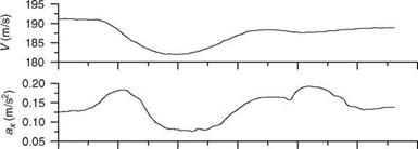
One of the purposes of acceleration and deceleration maneuver is to estimate the drag polars at high angles of attack. After trimming the aircraft, the pilot reduces the power to idle and decelerates to the minimum desired speed (a few knots above stall). He or she can hold altitude with only pitch control. Then the throttle is moved quickly to full power and the aircraft is allowed to accelerate. On reaching the maximum speed, the power is reduced to idle and the aircraft decelerates back to the starting trim speed. The maneuver should be performed smoothly. The overall altitude should not change more than 35 m. The power transition should be quite smooth.

2

image1331

0

6

Подпись: JO O' O'

image134

3

0

image135
-3 4 -6

7.7.4 WUT Maneuver

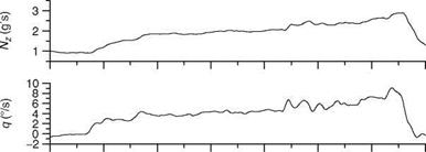
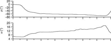
In WUT maneuver the pilot starts banking 2000 ft above the test altitude and then increases the load factor by pulling up slowly from 1g to the maximum permissible g at 0.5g to 0.8g/s rate. The speed is maintained by reducing the altitude and the throttle deflection is kept constant. This maneuver is useful to get the data for performance above M > 0.4 and from 1g to maximum g. Since bank angle is progressively increased from 0° to 80°, while pulling the stick, the aircraft starts turning in ever decreasing circles. Actually the pilot begins with a level turn and

16

8

Подпись: o

image137

0

-8

-16

Подпись: 0 3 6 9 12 15 18 21 Time (s) FIGURE 7.10 SD performance maneuver time histories.

-24

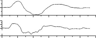
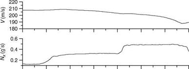
increases the bank angle. Since the nose drops due to increasing bank angle, he or she increases the AOA to maintain speed. This continues until the stall is reached or the g limit is reached. WUT is thus a descending spiral and will become tighter and steeper with increasing g. The aircraft will be in a steep nose down altitude with high bank angle. Subsequently, recovery to level flight is initiated. WUT should be performed with smooth increase in g and speed change should be minimal within 5-10 knots. Typical WUT maneuver flight-time histories are shown in Figure 7.11.

image139

image140

image141

image142

FIGURE 7.11 WUT performance maneuver time histories.

Experience with flight data analysis has shown that no single maneuver, no matter how carefully performed and analyzed, can provide a definitive description of the aircraft motion over the envelope or even at a given flight condition in the envelope. Thus, it is always desirable to obtain data from several maneuvers at a single flight condition or a series of maneuvers as the flight condition changes. Often, two or more such maneuvers are analyzed to obtain one set of derivatives. This is more popularly known as multiple maneuver analysis.

7.8 SPECIFIC MANEUVERS FOR ROTORCRAFT

The rotorcraft, unlike fixed-wing aircraft, is more complex with the main rotor playing a key role in defining the overall dynamics of the flight vehicle. In rotorcraft, the off-axis responses cannot be ignored, as these are more often than not of similar magnitude as the on-axis responses. The interference effects from the main and tail rotors and the presence of vibrations at low frequencies further complicate matters. A variety of flight test maneuvers are therefore required to generate sufficient information to identify mathematical models with increased reliability for the rotor – craft. Normally, for identification of rotorcraft stability and control characteristics, inputs similar to those for the fixed-wing aircraft, e. g., doublets and 3-2-1-1, are applied to excite the longitudinal phugoid, pitch, and the lateral DR and spiral modes. Frequency sweep inputs are also used in good measure to generate flight data for rotorcraft system identification. An excellent insight into various aspects of rotorcraft identification is available [14].

For rotorcraft HQ testing, ADS-33 stipulates the mission task elements (MTE) to be performed [15,16]. These are treated as HQ tasks, and mission-oriented maneuvers are flown by pilots who assign subjective pilot ratings using the Cooper-Harper handling qualities rating (HQR) scale. The performance of a helicopter during piloted mission tasks ultimately defines its HQ. ADS-33E specifies nearly 23 MTEs. Execu­tion of these mission maneuvers, which includes maneuvers like Hover, Landing, Hovering Turn, Pirouette, Vertical maneuver, Slalom, Sidestep, Deceleration to Dash, and Pullup/Pushover, generate a large amount of extremely valuable data for HQ evaluation. A typical rotorcraft flight maneuver is shown in Figure 7.12.

A few of the flight test maneuvers (ADS-33D) required to be performed on a rotorcraft to evaluate its HQ performance are described next [17]:

Hover: At a ground speed between 6 and 10 knots, at an altitude of less than 6.1 m, transit to hover, and maintain a precision hover for at least 30 s. This should be done in moderate wind from the most critical direction.

Hovering turn: At an altitude less than 6.1 m complete a 180° turn from a stabilized hover. With moderate wind from the most critical direction, perform the maneuver in both directions.

Bob-up/Bob-down: Bob-up to a defined reference altitude between 12.2 and 15.2 m from a stabilized hover at 3.05 m. Then stabilize for at least 2 s. Reestablish the

3.5 m stabilized hover by bob-down. Perform the maneuvers in moderate winds from the critical azimuth.

Acceleration/deceleration: From a stabilized hover rapidly increase power to nearly maximum and maintain altitude constant with pitch altitude. Accelerate to 50 knots at constant collective. After reaching the target speed, initiate deceleration by aggressively reducing power and holding altitude constant with pitch altitude, and then stabilize hover.

Sidestep: At a selected altitude below 9.15 m, starting from a stabilized hover, initiate a rapid and aggressive lateral translation, with a bank angle of at least 25°, while holding the altitude constant with power. After achieving a lateral velocity within 5 knots of maximum (or 45 knots), initiate deceleration to hover at constant altitude. Establish stabilized hover for 5 s and repeat in the opposite direction.

The above maneuvers are also specified with certain performance/desired parameters in ADS-33D. For example, in ‘‘hover,’’ the altitude should be maintained within ±0.61 m, the horizontal position should be within ±0.91 m and the pilot should be able to stabilize the helicopter in hover within 3 s.

The pilots need to pay extra attention to avoid exceeding the structural, aerody­namic, or control limits of the helicopter, while flying it to exploit its capability in the complete flight envelope. Piloted simulation evaluations should be made to investi­gate possible ways of alerting and aiding the pilot when close to transmission limits. Aggressive maneuvers can be flown in the simulator and the pilot reaction to various cues (like collective stick force feedback, aural cues, voice cues, and visual HUD cues) can be evaluated. The rotor rpm and rotor transmission limits should be monitored and evaluated. The active flight control approach can effectively eliminate uncommanded limit exceedance in high-aggression and large-amplitude maneuvers. Pilot cuing for impending limits can be based on the predictive capabilities of artificial neural networks (ANNs), which can be trained using helicopter flight test load survey database.

Roller Coaster (Pullup/Pushover) Maneuver

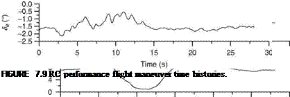
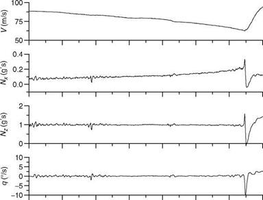
The Roller coaster (RC) maneuver is used to determine the aircraft drag polars. Starting from a trimmed level flight (this condition is not really necessary), the pitch stick is first pulled to slowly increase the normal acceleration from 1g to 2g (at the rate of roughly 0.1g/s) and then returned slowly to level flight in the same fashion, i. e., to 1g. Then the stick is pushed slowly, causing the acceleration to change from 1g to 0g at a slow rate and then returned slowly to trimmed level flight. This is a dynamic maneuver in the vertical plane with load factor varying from 0g to 2g or up to 4g as the case may be. The thrust should be kept constant and the speed variation should be minimal. The data are recorded at least for about 25-30 s in this slow maneuver, which covers low angle of attack range (0°-10°) and Mach number from 0.4 to -0.9. The speed should be kept constant in the beginning. This maneuver can also be performed up to 4g if found necessary. Typical RC maneuver flight-time histories are shown in Figure 7.9.

7.7.1 SD Maneuver

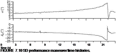
The purpose of SD maneuver is to determine the drag polars in the high AOA range. The maneuver is performed in the vertical plane and the Mach number range is 0.4 to low speed range. The aircraft is trimmed for level flight at the chosen flight condition. Then the elevator stick is pulled slowly to maximum AOA and then recovery is made from the stall entry. The data are recorded for 25-30 s. The thrust must be kept constant. Typical SD maneuver flight-time histories are shown in Figure 7.10.