Category FLIGHT MECHANICS MODELING and ANALYSIS

Mass, Inertia, and Center of Gravity Characteristics

Beside other requirements, an adequate knowledge about the mass and inertia characteristics is also important for accurate flight simulation and identification of aircraft stability and control derivatives. Nondimensional moment derivatives are directly influenced by the inertia calculations, while force derivatives will be straightway affected by the errors in aircraft mass calculations [7]. The moment of inertia information is difficult to obtain as it not only depends upon the placement of the test equipment but also on center of gravity (CG) variation during flight. The way the fuel is consumed during the flight, e. g., the forward tank, followed by the wing tanks and so on, can affect the moments of inertia. Determination of inertia from special oscillation test rigs is not practical [8]. A manufacturer’s data are mostly for

Подпись: xCG Подпись: (6.2)

moment of inertia calculations. For a 4 t class of trainer aircraft, typical values of the moment of inertia Ix, Iy, Iz, and Izx will be like 4,500, 18,000, 20,000, and 1,500 kg m2. The cross-product of inertias Ixy and Iyz is small and hence usually neglected. Information on fuel consumption is useful to compute CG travel and the actual mass of the aircraft at any time during the flight. To correct the flight data for the offset in sensor locations from CG, we need to compute the actual distance of CG from the reference vertical datum rather than express it in terms of percentage of the mean aerodynamic chord (MAC). The actual distance of CG in meters from the vertical datum can be computed as follows:

where c is the mean chord length and xLE is the extreme leading edge location of the MAC.

Aero Database

In general the aero database obtained from wind tunnels is supplied in tabular formats along with the application formulae [1,6] that are used for computation of force and moment coefficients; the latter form a part of the EOMs (Figure 4.1). The EOMs are then numerically integrated to obtain the dynamic responses of the aircraft, which are called the time histories. An application formula for the axial force coefficient of a typical aircraft is given as

Cx = Cxa0ds (m&ch,8 siat) + Cxads(mach, a ,8 sklt) + CI„c(a, mach, UC) + CxAis(mach, a,8AB)

^ Cxdlds(mach, a,dlob, dslat) * KCxdlob(mach, a,dlob) ^ Cxdlds(mach, a,dlib, dslat)

* KCxdlib(mach, a,dlib) ^ Cxdlds(mach, a,drib, dslat) * KCxdrib(mach, a,drib)

^ Cxdlds(mach, a,drob, dslat) * KCxdrob(mach, a,drob) (6-l)

In the parentheses the terms are independent variables, which signify the dependen­cies of the coefficients on these terms. The above application formula is translated into the following expression:

Coefficient for axial force = Cx for a = 0 + Cx due to a with slat deflection + effect of undercarriage (up or down) + effect of airbrake deflection + Cx due to left outboard elevon (combined elevator/aileron) deflection * factor on Cx due to left outboard elevon deflection + Cx due to left inboard elevon deflection * factor on Cx due to left inboard elevon deflection + Cx due to right inboard elevon deflection * factor on Cx due to right inboard elevon deflection + Cx due to right outboard elevon deflection * factor on Cx due to right outboard elevon deflection. Similar application formulae are available for other five coefficients. The intermedi­ate values of a given coefficient base for the specific independent parameters can be obtained by interpolation (Exercise 6.1).

AIRCRAFT SUBSYSTEMS DATA/MODELS

Aircraft consists of several systems that require mathematical models if full dynamic simulation is needed: aircraft flight mechanics, actuation system, sensors, engine, navigation, landing gears, and control system. In addition, the environment and display systems are important. The mathematical models of these subsystems are supposed to be known and the fidelity of simulation depends on how close these mathematical models are to the actual subsystems (dynamics) [1]. In general certain important modeling aspects have been addressed in Chapters 2 through 5 and Chapter 9. For flight-dynamics simulation, the model structure, the EOM, and the aerodynamic derivatives (often the knowledge of aerodynamic coefficients is enough) are assumed known. The HW/SW configuration should be strictly main­tained for faithful reproduction of flight trials/conditions and repeatability of the various simulated tasks performed. Since several HW/SW modules need be inter­connected and integrated to realize the flight simulator’s functioning, it is important not only to test individual subsystems and modules for their accurate functioning, but also to see that the tasks performed by these modules are properly synchronized in time and sequence of operation. In addition to these subsystems, logic circuits, radio aids, and navigation-related components/SW are needed to realize high-fidelity and full-fledged flight simulators.

Simulation of Flight Dynamics

6.1 INTRODUCTION

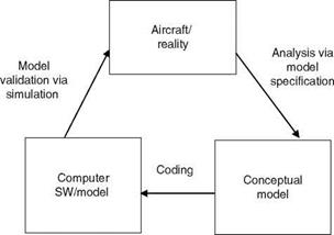
Simulation of flight dynamics is a very important and crucial component of any large aircraft development program. Simulation is meant to replicate the real-life environ­ment and the behavior of an aircraft in flight, mainly on ground [1-5]. When similar replication is done in air it is called in-flight simulation (IFS). Wind tunnel is a type of simulation (Appendix A). Simulation can be used when the system does not exist, e. g., development of a new aircraft. It is also used when experiments with real systems are very expensive and not very safe, especially for training new pilots/flight test engineers/crew. A simulator is thus a very useful system/device for the study of dynamic behavior of aircraft (including rotorcraft, missiles, UAVs, MAVs); to try out difficult and sometimes risky experiments; to conduct failure mode trials to test flight-control laws; to get the feel of the various systems and robustness and reliability of other critical subsystems. It really calls for a systems approach from theoretical, analytical modeling to practical evaluation/validation of the flight mechanics/flight control/handling qualities behavior of the simulated vehicle. One guesstimate is that in the world there would be more than 600 simulators, which are used for training and maintaining the skills of military and civilian aircrew. Research flight simulators are used for evaluating the design options without primarily build­ing the prototypes of aircraft, thereby saving considerable time, effort, and cost. Various design implications can be studied and evaluated in research simulators. There are several benefits of using flight/research simulators: (1) increased effi­ciency, since there is no limitation of airspace or adverse weather conditions, (2) enhanced safety, (3) drastically reduced training cost, and (4) rehearsal of several situations that cannot be practiced in real flight. The design, development, and use of a flight simulator involve considerable modeling and analysis exercises. One goes from the reality to a conceptual model via analysis, from this to computer model via programming, which then simulates the reality. Figure 6.1 depicts this very clearly. Using procedures of verification, the computer SW/program models are confirmed as an adequate representation of the conceptual model. The computer models are then validated for possessing satisfactory accuracy in comparison with reality by extensive simulation for the intended flight-like maneuvers and exercises. Thus, the process of flight simulation is an iterative one.

Simulation can be at various levels: software (SW), hardware (HW), or both [1]. Mainly for simulation of aircraft dynamics, one needs to mathematically model the dynamics of every subsystem that is deemed important and contributes to generate the time responses of the aircraft [2,3]. For accurate simulation, high-fidelity models

image79

Model

verification

FIGURE 6.1 Modeling and analysis is triad for flight simulation.

are needed. Simulation is thus pretending the reality, and for visual impact (like environment, runway conditions) one uses the concepts and techniques of visual software and virtual reality. Often the instruments on the cockpit instrument panel are ‘‘soft instruments.’’ There are multifunction displays and the actual instruments required in the simulator are just a minimum set. This reduces the maintenance efforts, volume, and cost. Therefore, simulation is meant to provide almost real-life environment, controls, and feel of the actual aircraft/system that is being simulated. If one is in the ground base simulator (say without motion), but with strong visual cues, one feels that one is in the actual aircraft as far as the dynamic behavior and visuals are concerned. If the simulator is used for aiding design, development, and validation of flight-control laws, then a test pilot, engaged for flight testing of the aircraft being designed, or a control engineer should ‘‘fly’’ the simulator. This simulator is then called pilot/engineer-in-the-loop simulator [4]. It consists of cock­pit, controls, throttle, switches, data acquisition system, and visualization/executive SW and can be run in a batch or real-time mode. A batch simulation works in a preprogrammed and multiuser mode and computer-generated inputs can be used. Batch simulation does not need any hardware except a PC. A preprogrammed command could be given as input to the computer in which the computation of flight dynamics and other math models is carried out. The computer monitor would serve as the display system for the batch simulation results.

In a hardware-in-loop simulator (HILS), the actual flight computer with control law software is also incorporated for testing. HILS is used for testing safety critical flight-control software as well as flight computers in an easily controlled laboratory environment at a relatively low cost. In an iron-bird simulator (wherein ‘‘ironangles/ beams’’ are used), the subsystems like actuators, hydraulics system, computers, and cabling are incorporated and interconnected to represent the aircraft more com­pletely for ground testing. A full-fledged simulator, with or without motion cues,

image80

FIGURE 6.2 Components of a typical soft-flight simulation scheme.

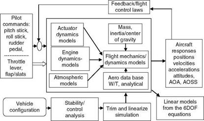
is called a real-time simulator (RTS); the test-pilots would fly and try out all the flight test maneuvers on it, before flying the actual aircraft (for which the RTS is meant). It includes cockpit, control stick, pedals, and throttle. Normally, it would be a single user mode. RTS can be used for certification of flight-control laws, at least for some important flight conditions. Figures 1.2 and 6.2 show the schematic of a ‘‘soft’’ flight simulator with associated control-law development/validation process integrated with many subsystems, which play an important role in the development of the simulator facility [4].

Both fix – and motion-based flight simulators play a vital role in the evaluation of flight-control laws and handling qualities of the aircraft right at the development stage and are used to gain enhanced confidence in the performance of the aircraft. The idea in variable stability research aircraft/in-flight simulation (VSRA/IFS) [5] is that the static and dynamic stability characteristics of this simulator vehicle can be varied over a wide range using feedback control laws and that this host simulator (aircraft) would be used to fly like the guest aircraft that is being simulated, and hence the name IFS. A variable feel system should be included to simulate various control system characteristics. The other uses of this facility are pilot training for advanced vehicles and the solution of specific stability and control-design problems. These simulators provide motion and visual cues that are more realistic than some ground-based simulators. In addition to this, airborne simulators provide the stresses and motivation that can be attained in the actual flight environment to the pilot. Also, IFS can be used to evaluate ground-based simulators.

The development of VSRA/IFS could proceed in three phases:

1. Literature survey on the process of development and related methodologies, study of existing aircrafts (fighter, trainers, and transport), systematic evaluation of these with a view to adopting one of these for the intended

purpose, other HW/SW requirements, related cost and manpower skill requirement and whether all that is available and how to tap it. Maintenance and related aspects should be addressed initially. Finalization of the strategy of development and planning.

2. Systematic development of the facility in a modular fashion, upgradation of the selected aircraft with HW/SW (avionics/instruments/flight control, etc.) and various integration studies, exercise, etc. Preliminary evaluation of the performance of the host aircraft (IFS) and improvements there from. Detailed analysis of the ongoing development process and feedback from the users of the facility.

3. Refinement based on the trial runs and HW/SW configuration improve­ment if needed. Training of the pilots and research evaluations, extensive flight data analysis, and control-law evaluation and refinement if needed, performance evaluation through several mission-related tasks, etc.

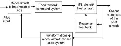
The above strategy is also applicable to the development of other simulators, except that an actual aircraft is not required, instead its mock-up would be needed. Since for the IFS a different aircraft (host) is used to simulate the dynamics and control laws of the aircraft that is being developed and simulated, the flight dynamics/control bandwidth of the host aircraft has to be greater than that of the simulated aircraft. The IFS is an aircraft whose stability, feel, and flying charac­teristics can be changed to match those of ‘‘to-be-simulated’’ aircraft. The IFS is useful in realistically and safely evaluating a new or modified aircraft before its first flight and before even committing the aircraft to production. A schematic of the IFS’s response feedback system is shown in Figure 6.3. What would physically fly is the host aircraft and not the model aircraft that is simulated; however, the host aircraft is made to/will behave like the guest aircraft. The augmented dynamics of the simulated aircraft are matched by the host aircraft by feeding back appropriate motion variables to the control surfaces. One can easily imagine that the process from ground-based to final IFS, and for many other types of simulators, involves

image81

increasing complexity, sophistication and cost, and of course, enhanced confidence in the performance/testing of the aircraft.

The main purpose of any simulator is to obtain the dynamic responses of the aircraft for specific inputs and in the presence of simulated environment, e. g., turbulence and gust. Often the list of these specific inputs is very large. Many such practicable pilot command inputs (signals) are discussed in Chapter 7. All such maneuvers can be tried out in an RTS wherein the pilot sits in the cockpit and uses the command sticks/wheel and rudder pedals to excite the modes of the aircraft. Thus, flight simulation/simulator provides reasonably accurate, sometimes high-fidelity representation of the sensation of sound, touch, visual scenario (often called simply the visuals), and acceleration feels (for motion-based simulators) as encountered in flight. Thus, flight simulation is very essential in aircraft design and development programs. It could be a totally and fully virtual reality simulator with powerful visuals. Training simulators are also used for pilot training before they can fly transport or fighter aircraft. For phases like landing, takeoff, and tracking tasks, a longer period of simulation run (e. g., 10 to 15 min) is required and needs a designer or an engineer/pilot in the loop.

Thus, the flight simulation process centers around: (1) study of flight dynamics (including the coordinate systems/transformations) and formulating these in mathe­matical language, which translates to mathematical models, in fact into equations of motion (EOM) (Chapters 3 and 4) and (2) the coding of these math models and implementing the codes/algorithms via a suitable programming language (pref­erably C) in a computer. Overall functioning of flight simulation (process) involves (1) developing the performance requirements, (2) integrating subsystems/ subcomponents, (3) guiding and validating the design of the vehicle and the flight – control laws, (4) supporting the flight testing of the aircraft and reducing the cost of the actual flight tests, (5) investigating inaccessible environments and practice, other­wise, dangerous procedures and exercises, (6) pilot/crew training, and (7) supporting R&D in all the above aspects via the flight-simulation process and exercises.

EPILOGUE

Since the direct use of EOMs in their full form is usually avoided, except in the full dynamics flight simulation, simplified models are useful in various applications: linear models for control law design, quick analysis to understand the dynamic characteristics of the vehicle, mathematical modeling from flight data, and related handling qualities analysis. This evokes the need of the system’s approach in understating and use of flight mechanics aspects in various aerospace engineering applications. In Ref. [20], the authors give the literal approximate factors to obtain approximate relations for TF poles and zeros, in terms of the stability and control derivatives of the atmospheric vehicle.

EXERCISES

5.1 The aerodynamic derivatives for a transport aircraft are given as

Lo = 0.0095, Lp = -2.0374, Lr = 0.876, LK = -5.933, LSr = 1.034,

N0 = 0.03, Np = -0.177, Nr = -0.57, NSa = -0.292, NSr = -1.749

Write an appropriate mathematical model and obtain various TFs and fre­quency responses of the lateral-directional model using MATLAB functions. Determine the frequency and damping ratio of the mode.

5.2 What is the significance of the natural frequency, say of the SP mode, from the pitching moment point of view?

5.3 Recall Equations 3.23 and 5.32, say for rolling moment and yawing moment. Assume the neutral static condition and neglect cross-coupling inertia terms and obtain the relation between lateral-directional static stability and dihedral (static stability) derivatives in terms of control effectiveness derivatives (see Chapter 4).

5.4 The aerodynamic derivatives of a transport aircraft in phugoid mode are given as

Xu = -0.011, Zu = -0.1583, u0 = 111 m/s

Use the phugoid model of Equation 5.20 and obtain the frequency responses and other characteristics.

5.5 For an airplane with the following characteristics compute (1) the lateral-direc­tional dimensional derivatives.

Сур = -1.125; Cyr = 0.8; С„э = 0.27; CHr = -0.5; = 0.28;

Cnsr = -0.16; Cyp = 0.17; Ckr = 0.0697; Ch = -0.133;

C1p = -0.96; C1r = 0.42; Cnp = -0.1; Ckr = -0.2496

Other data are

Ix = 105,500 kgm[3];

Iy = 250,000 kgm2;

Iz

= 340,000 kgm2;

Ixz = 11,500 kgm2

V = 72.114;

r

= 0.72851 kg/m[4]

b = 21.5 m;

S = 65 m2;

mass = 5,000 kg;

u0 = 140 knots;

H = 5100 m

5.9 If you want to add another state variable in the phugoid model, which one would you add?

5.10 If the moment-speed derivative in Equation 5.22a becomes sufficiently nega­tive, what happens to the phugoid mode characteristic?

5.11 In SP mode/model, which aerodynamic derivative would have the largest influence on the natural frequency?

5.12 In SP mode which aerodynamic derivatives would have influence on the damping ratio?

5.13 What is inertial and aerodynamic ‘‘damping’’ in SP mode?

5.14 In phugoid mode which is the most influential aerodynamic derivative and in what way?

5.15 Which aerodynamic derivatives have the most significant influence on the DR frequency?

5.16 Which are the most effective aerodynamic derivatives in spiral and roll sub­sidence modes?

5.17 Which is the most effective DR damping aerodynamic derivative?

5.18 Explain the name spiral divergence.

5.19 Derive the condition for spiral stability.

5.20 Using small disturbance theory and assuming wings-level symmetric flight condition, show that the expression W = —PV + QU+ g cos Q cos Ф + Az reduces to w = qu0 — gU sin U0 + az.

LIGHTER-THAN-AIR VEHICLE/BLIMP DYNAMICS

Lighter-than-air-vehicles have several advantages and are finding increasing appli­cations in various tasks such as surveillance and advertising. Modern aerostats use helium for lift and consist of a power supply system. A two-way fiber-optic datalink is provided for sensor data and control. The low-pressure differential allows them to sustain for long. They are also difficult to detect with radar. Due to these features, the demand for the use of aerostats for surveillance is continually growing and, as they are less expensive, they offer a viable alternative to satellites for certain limited tasks.

In this section, we briefly discuss the mathematical model of an airship. As for the fixed-wing aircraft, the basic derivation of EOMs of an airship is based on rigid body dynamics [16]. One noticeable difference in developing the model equations for an aircraft and an airship is the consideration of buoyancy in the latter case. To account for the apparent mass effect due to the large volume of air mass displaced by an airship, EOMs are usually written about the center of buoyancy. In Ref. [17], effects of the change in the position of the CG, as a result of venting or intake of the ballast air, is also modeled. Reference [18] suggested simplification in the model equations by determining the change in the position of the CG and translating all the forces, moments, and inertias to CG to compute the airship dynamics. This results in EOMs that are similar to those discussed in Chapter 3 for the fixed-wing aircraft. In state-space form, these can be expressed as

X(t) = f [x(t), u(t), Q] (5.56)

where, for a 12th-order system, the state vector x consists of x = [u, v, w, p, q, r, f, U, С, X, Y, H]

The vector Q is a collection of the stability and control derivatives and u is the control input vector. Computing the center of mass location and translating the moment of inertias to the center of mass lead to decoupling the accelerations and writing EOMs in the conventional form. Since the variables X, Y, and С do not couple with the rest of the equations, mostly a ninth order linear model comprising the longitudinal states u, w, q, U, H and the lateral states comprising v, p, r, f is used to analyze the modal characteristics of an airship.

Due to the buoyancy and apparent mass of the airship, its climb performance is different from that of the conventional fixed-wing aircraft [18]. For an aircraft, we have

Подпись:T — D — Wsing = 0 L — Wcos g = 0

TABLE 5.5

Some Aerostat Derivatives

Derivative/0

Numerical Value

CL

La

0.02

C

—0.027

Cmq

—0.00021

Cb

—0.0000009

Cp

—0.00003

Cb

0.00087

where W is the weight, T is the engine thrust, D is the drag, L is the lift, and g is the flight path angle. Considering the buoyancy force B in the case of an airship, the force balance equations in climb are

T – D + (B – W) sing = 0 L — W cosg = 0

The first of the above equations describes the force balance in the direction of flight path while the second describes the force balance perpendicular to the flight path. The net buoyant force (B — W) for an airship in climb is positive. The velocity of the airship will undergo a change if the first equation is not balanced, and the airship flight path angle will undergo a change if the second equation is imbalanced.

Linearized EOMs provide the modal characteristics of the airship. The longitu­dinal modes of an airship generally consist of an oscillatory mode with low damping and a heave mode. Unlike a conventional aircraft, the airship has no mode equivalent to the phugoid mode as the coupling between the forward speed and heave mode is missing in the case of an airship. The lateral-directional modes comprise the DR mode, which is generally an oscillatory stable mode with high damping and a roll mode, which is an oscillatory stable mode with very low damping. Airship can also show sideslip subsidence and yaw subsidence modes. Typical aerodynamic deriva­tives for an aerostat/blimp configuration are given in Table 5.5 [18]. Reference [19] discusses the airship modal characteristics in greater details.

MAV DYNAMICS

Biologically inspired MAVs are small autonomous flying vehicles. Their dimension could be smaller than 15 cm, or sometimes smaller than 300 cm, latter toward mini-air vehicles (MiAVs). MAVs are used for reconnaissance over land, in build­ings, for collecting evidence of industrial faults, and for survey over hazardous places or nuclear sites. For design and development of these vehicles one needs to understand aerodynamics, structural aspects, and propulsion physics at a very small scale. Due to their small size, there would be limited or no space to carry avionics, which would otherwise carry out various navigation tasks [14].

Operational challenges of MAVs are related to low Reynolds number (^10e + 4), presence of gust and obstacles at low altitudes, microsize and weight, need for compact power pack, microsensors and actuators, and aeroelastic coupling. MAVs (and MiAVs) could be fixed wing, rotary wing, or flapping wing. Flapping wing flight is exhibited by millions and millions of species (bats, birds, and insects). A flapping wing MAV can be viewed as a single nonlinear dynamical system with integrated fluid, structure, and control systems components.

Research in the areas of MAVs can offer new and computationally efficient solutions to problems of design, propulsion/energy efficiency, structural aspects, machine vision, and navigation. Currently, the research is focused in three main areas:

• Research to study the aerodynamic characteristics of low-aspect ratio wings at low Reynolds number.

• Wind tunnel experiments for flow visualization. Aerodynamic coefficients in the form of lookup tables of stability, dynamic, and control derivatives are also obtained from such experiments.

• Numerical simulation based on CFD and wind tunnel experiments.

Подпись: > Подпись: Guidance and contro )l Flight dynamics

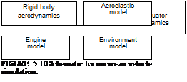
Today, autonomous aerodynamic control of MAVs is of much interest. The issues of flight mechanics and flight control for MAVs are of particular concern. In general, MAV dynamics can be modeled using the well-established set of rigid body EOMs for aircraft. Since MAVs are extremely light and susceptible to gusts, a possible way to avoid the degradation in their performance due to gusts is to build MAVs with higher flexibility [15]. Flexible MAVs will have the ability to absorb the wind energy and reduce the effect of gust, thereby improving the MAV’s overall performance. Models for simulation of MAV dynamics would therefore also require appropriate representation of flexibility effects in aerodynamic models. Figure 5.10 shows a simplistic layout of the simulation model for MAV.

UAV DYNAMICS

UAVs could perform tasks that are difficult for manned aircraft, e. g., chemical or biological warfare missions. UAVs can also be used to test and verify technologies for UAV and for general aviation aircraft. The utilization and operation of UAV entail less risk to humans in combat. UAVs can also be freed from the limitation of human operators. This would improve the performance of UAVs. UAVs utilize various advanced technologies: (1) data/signal processing, (2) off-board on-board sensors, (3) communications links, and (4) integrated avionics and flight control. UAVs could be remotely piloted or they could be autonomous with an autopilot. They can operate at altitudes above 70,000 ft, have higher maneuverability and longer endurance, and can carry optical sensors and radars. However, they need large communications bandwidths. UAVs could also be equipped with aircraft-like con­trols: elevators, ailerons, rudders, flaps, extensions of wings, and undercarriage.

In an autonomous UAV, humans have no direct control over the vehicle. One form of autonomy is the radio-controlled model airplane. The most complicated UAV would be the one that uses a rule-based fuzzy logic (see Chapters 1 and 9) to detect, identify, and attack a mobile target. Flight dynamics modeling of UAVs presents some unique challenges. UAVs are lighter than manned aircraft and hence they have higher natural frequencies. To simulate the dynamic motion, the nonlinear fully coupled EOMs of an aircraft, discussed in Chapter 3, can be used. Simplified EOMs discussed in the present chapter can also be used to carry out preliminary studies relating to UAV performance evaluation. Any one of the following model forms can be selected for UAV dynamic analysis

1. Nonlinear fully coupled equations as described in Equations 3.22, 3.23, and 3.28

2. Linear coupled, e. g., Equation 5.5

3. Nonlinear decoupled, e. g., Equations 5.6 and 5.23

4. Linear decoupled, e. g., Equations 5.16, 5.20, and 5.25

Working with the fully coupled EOMs in option (1) can be time consuming and complex. Therefore, for control system design, designers usually make use of linearized or decoupled models given in options (2), (3), and (4). Of course, one has to keep in mind the limitations of these models. The linearized EOMs are valid in the small range around the trim point when excursions from the reference flight condition are small. Decoupling is also valid when there is negligible interaction between the longitudinal and lateral-directional motion.

In using the above set of EOMs for UAVs, the following assumptions are made:

1. UAVs are rigid bodies and flexibility effects are not considered.

2. They have a conventional configuration (i. e., aft tail).

3. Symmetry about the XZ plane is assumed.

4. The effect of thrust on lateral-directional motion is neglected (Equation 5.25). Reference [13] gives more details about the dynamic modeling of UAVs.

Evaluation/Validation of Linear Flight Dynamics Models

Evaluation of a flight dynamic model implies checking the accuracy and adequacy of the identified model against the real system and to ensure that, to the extent possible, it is a true representation of the system. Evaluation methods can give valuable clues to the possible sources of error that might lead to discrepancies between the model output and flight measured response. Having done the model evaluation, one can use it to evaluate the aircraft dynamics, performance, and handling qualities. Such models are also useful in evaluating and updating flight-control systems or investi­gating aircraft design modifications.

Evaluation of the dynamic models can be done at two levels: (1) adequacy of the model structure and (2) adequacy and accuracy of the identified derivatives.

Since the dynamic models for fixed-wing aircraft and rotorcraft are based on phenomenological considerations, there is limited scope of making changes as far as the model structure is concerned. However, the set of derivatives to be identified from flight data is not always obvious, particularly if the system under consideration is operating in nonlinear regions.

The presence of too many secondary derivatives can lead to correlations among parameters, which can adversely affect the identification results. On the other hand, too few parameters can cause the model to produce an inadequate response match. There is no unique method to arrive at a reduced parameter model. One approach to recognize and retain significant parameters in the estimation model is to use stepwise linear regression [12]. Another approach is based on the Cramer-Rao bounds (CRB) of the derivatives. The CRB of the identified parameters are obtained from the information matrix, which is anyway computed by the output error algorithm during the estimation process. Derivatives that are secondary in nature and show exception­ally high standard deviations are dropped (fixed to zero) from estimation each time
the model is reconverged. Though time consuming, this approach helps to provide a reduced parameter set for identification.

Compared to fixed-wing aircrafts, helicopters pose greater modeling problems because of their highly cross-coupled and nonlinear dynamic behavior. Nonlinea­rities in helicopters could arise from compressibility effects, tip vortices, blade elasticity, inflow dynamics, lead-lag effects, torsion, etc. and significantly alter the flow field over the blades. The aerodynamic forces and moments generated at the main rotor strongly influence helicopter dynamics. At the basic level, classical 6DOF models are used assuming the blades to be rigid. The 6DOF model treats the rotor dynamics in quasi-steady form. This may, at times, lead to degradation of the estimated results. Including additional degrees of freedom due to blade flapping and inflow dynamics allows for better representation of rotorcraft dynamics at higher frequency leading to improved estimates.

The adequacy and accuracy of the identified models can be assessed by any one of the following methods:

• Comparing the estimated values of the identified derivatives with values obtained from other sources, like analytical values, CFD results, or wind tunnel data.

• Comparing the estimated derivative values from different sets of flight data gathered from similar maneuvers at the same flight condition.

• Comparing the model responses with the data not used in identification of the derivatives. Normally, it is advised to keep half the data for model development and half for model validation.

• Assessing based on the physical plausibility of the identified derivatives. Physical knowledge of the system being modeled is essential to correctly interpret the results and validate the model.

It needs to be emphasized here that no mathematical model is perfect. Therefore, model evaluation, to some extent, is subjective. Comparative plots of the estimated and measured time histories alone are not sufficient to evaluate a model. A combin­ation of the above-mentioned criteria should be used. Fully evaluated and validated dynamic models are essential for flying quality evaluation, piloted simulations, and for the design and upgradation of aircraft flight-control system.

Stability Derivative Models

The linearized equations for the rigid body and rotor dynamics, in the state-space form, can be expressed as

Подпись: (5.41)Xb = AbXb + Abrxr + Dbu

xr = Arxr + ArbXb + Dru

where xb represents the basic 6DOF rigid body state vector, xr represents the higher – order dynamics that may include flapping and lead-lag dynamics, and u represents the control input vector.

xb = (u, v, w, p, q, r, f, U, C, h)

xr = (u, v, w, p, q, r, f, U, C, h, as, bs, … ) (5.42)

u (dlon, dlat, dcol, dped)

Ab and Db matrices denote the rigid body dynamics in the absence of rotor dynamics while Ar and Dr matrices represent the rotor flapping dynamics. Arb and Abr matrices represent the rotor-body and body-rotor coupling.

Taking Laplace transform of Equation 5.41 and solving for xr, we get

sxr = ArbXb + Arxr + Dru

(si — Ar )xr = ArbXb + Dru (5.43)

xr = (si — Ar )—1Arbxb + Dru

Expanding (si — Ar)—1 in a series form, we get

(si — Ar)—1 = – A—1 [i + A—:‘s + A—2s2 + A—3s3 + •••] (5.44)

Substituting the above series expansion for (si — Ar)-1 in Equation 5.43 and taking inverse Laplace yields the following solution for Xr:

xr A— Arbxb A— Arb-_b A— Arbxb ••• A— Dru

— A—2Dru — A—3DrX—————————————————– (5.45)

Equation 5.45 contains the control input and body states along with their higher – order derivatives. At equilibrium, the higher-order derivatives vanish and the rotor state xr can be expressed as

Substituting xr from Equation 5.46 into Equation 5.41 yields the following quasi­static model for xb:

Xь — Аьхь A Abr [ A – AffoXfo A – DruJ A Dьu Simplifying the above equation

Хь — [A – AbrAr 1Агь]хь + [Db – A^A,. 1D^|u (5.47)

or

-Хь — Aqs хь + Bqsu (5.48)

where AqS and BqS represent the quasi-static state and control matrices that comprise the rotor and rigid body stability and control derivatives.

5.6.2 Rotor-Response Decomposition Models

These models are formulated by decomposing the response of higher-order states into two components: (1) self-induced response and (2) response from rigid body motion. For example, the rotor state can be decomposed as

Xr — XrMR + Хгв (5.49)

where xr indicates the response due to main rotor dynamics and xr is the response due to body dynamics. Equation 5.41 for the rotor state can be expressed as

XrMR A XrB Ar(xrMR A XrB) A ArЬXЬ A Dru (5.50)

In the decomposed form, we have

Подпись:XrMR — ArXrMR A Dru – XrB ArXrB A ArЬXЬ

The approach used for obtaining the expression for Xr in Equation 5.45 can be applied to find a solution to Equation 5.51. The contribution to the rotor state from body motion is then given by

XrB Ar ^ь-^ Ar ArЬ-XЬ Ar ^ь-Ть ”’ (5.52)

Подпись: " XrMR Ar Arbxb Подпись: (5.53)

Assuming that the body dynamics are low-frequency dynamics compared to the rotor dynamics, the higher-order derivatives in Equation 5.52 can be neglected to obtain the instantaneous rotor response to body motion. Substituting Xr in Equation 5.49 by retaining only the first term in Equation 5.52, we get

Substituting xr from Equation 5.53 into the expression for xb in Equation 5.41, we obtain

xb Abxb A Abr [xr^R Ar Arbxb] A Dbu

On simplification, we get

xb [Ab Ar Arb]xb A AbrxrMR A DbU (5-54)

Comparing Equation 5.54 with Equations 5.47 and 5.48, we observe that the first term of Equation 5.54 is the quasi-static state matrix AqS. The rotor-response decomposition model can now be expressed as

Подпись: (5.55)xb AQSxb A AbrxrMR A Dbu

-^rMR = ArxrMR + DrU

The elements of the matrices in Equation 5.55 can be identified either from wind-tunnel testing or flight testing.