Category Flight Vehicle Aerodynamics

Unsteady 2D Airfoil

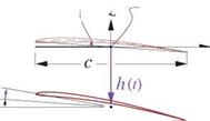
The unsteady 2D airfoil problem is important in many applications, such as prediction of gust loads on wings, cyclic loads on rotor blades, and the onset of flutter. See Bisplinghoff et al [53] for an overview. Here we will consider the case of a rigid airfoil moving at a uniform horizontal speed U, while undergoing unsteady heaving h(t) and pitching O(t) displacements about a baseline position and angle of attack a0, as shown in Figure 7.8. Note that the heave displacement h is defined positive down.

camberline Z(x) —, Midchord

" reference point

Подпись: Baseline position Displaced position Wgust Подпись:ao ‘

U x

Подпись: Inertial observerInerti

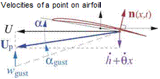
Figure 7.8: Airfoil moving at uniform horizontal baseline velocity U. Heave and pitch displace­ments h(t), 6(t) from baseline position give net resultant vertical velocity h + Ox at a some point x, which then define the local angle of attack a(x, t). Some vertical gust velocity wgust(t) produces an additional angle of attack agust.

3.1.5 Geometric relations

The assumptions of first-order thin airfoil theory will be employed here. The airfoil camberline shape is Z(x), with a negligibly small thickness. The geometric and flow angles are assumed to be small.

Z’ < 1 , ao, O < 1 , h, Oc, Wgust < U

Following historical convention for unsteady airfoil analysis, the airfoil extends over —c/2 < x < c/2, so the reference point x = 0 is at midchord, as shown in Figure 7.8.

3.1.6 Problem formulation

The problem will be formulated in the frame and the axes of the inertial Earth-based observer. The camber­line’s normal vector therefore rotates with the airfoil.

The small-angle assumptions give the following total velocity of a point on the airfoil.

Подпись: (7.38)Up(x, t) = — U x — (h + Ox) z

Подпись: W(x,t) Подпись: 1 2TT Unsteady 2D Airfoil Подпись: (7.39)

The perturbation velocity field is represented by a vortex sheet of strength 7(x) on the airfoil and wake. The wake portion is absent in steady thin airfoil theory (Appendix D), but is needed here to represent shed vorticity. In the Earth frame, the total vortex sheet strength gives the following instantaneous vertical fluid velocity w at any given location on the x-axis, which adds to any wgust already present.

In the airfoil frame, the corresponding fluid velocity at location x is then

Vrei = (w + Wgust) z — Up = U x+ h + Ox + w + WgustJ z (7.40)

which is then used in the usual flow tangency condition on the camberline.

Vrel ■ n = 0 (—c/2 < x < c/2) (7.41)

This applies only on the airfoil. In the wake, we must instead impose the zero pressure jump condition, by taking the x-derivative of the Др convection equation (7.22), which then becomes the y convection equation. The governing equations over the entire vortex sheet —c/2 < x< to are then stated as follows.

Подпись: ж dx' Y(x,,t) — c/ 2 x x' °Y + Up. dt dx Подпись: 1 2vr = Ua0 — UZ’ + h + (UO + Ox) + wgust (—c/2 < x < c/2) (7.42)

= 0 ( c/2 < x < to ) (7.43)

Unsteady 2D Airfoil Подпись: (7.44) (7.45)

The pressure loading required to calculate the lift and moment is obtained from equation (7.21). This in turn requires the time rate of the potential jump, which is defined in terms of the vortex sheet strength time rate.

Because equations (7.42) and (7.43) are both linear in y, their solution y(x, t) and corresponding Др^у) and Др^у) can be decomposed into five independent components, with each component determined entirely by one of the five righthand side source terms in (7.42).

Y(x, t) = Ya(x) + Yz (x) + Yh(x, t) + Ye(x, t) + Ygust(x, t) (7.46)

The first two contributions Y«,YZ are steady since they depend only on the fixed baseline angle of attack a0 and camberline shape Z(x), respectively. These are treated by standard steady first-order thin airfoil theory, as derived in Appendix D. This result for the steady case is

Подпись:Q = c£o + 2nao

cmc/4 = cmo

where ci0 and cmo depend only on the camberline shape. In the subsequent sections we will ignore these steady contributions and focus only on the three remaining unsteady parts driven by h(t), O(t), wgust(t) which determine Yh, Ye, Ygust, respectively, and also their corresponding unsteady lift and moment.

Wake convection

Wake convection
Wake convection

A major complication in calculation of unsteady flows is the evolution of the wake, both its doublet strength as well as its geometry. The physically correct wake shape is the streakline (in 2D) or streaksurface (in 3D) attached to the trailing edge. An example is shown in Figure 7.6 for a heaving airfoil. In the most physically accurate free wake case the wake shape’s evolution in time depends on the history of the velocity field of the airfoil+wake combination, and hence depends on the flow solution itself. This renders the problem nonlinear, since the kernel functions for the wake doublet sheet, in particular the r’ values in the pM integral (7.10), will now depend on the solution.

Wake convectionWake convectionPrescribed Wake, along TE path (linear flow problem)

Prescribed Wake, straight (linear flow problem)

Figure 7.6: Three different wake geometry models. In free wake model, spanwise wake roll-up typically occurs at locations of strong shed vorticity.

A further complication is that a free vortex sheet will in general undergo roll-up wherever the vorticity is concentrated. Steady flow problems which only have trailing vorticity typically have wake roll-up at the wake sheet’s wingtip edges, as sketched in Figure 5.4. Unsteady flow problems in addition also have roll-up caused by shed vorticity. The extreme deformation of the wake shape undergoing roll-up makes accurate tracking of this shape difficult and computationally expensive.

These complications associated with a free wake can be mostly eliminated by using the prescribed-wake as­sumption. Here the convection of the wake by the velocity field is ignored, and instead the wake geometry is prescribed explicitly. Two possible choices are shown in Figure 7.6. The simplest straight-wake assumption is quite adequate for modest airfoil motions, and is almost invariably used by Vortex-Lattice methods. The great advantage of a prescribed wake is that it renders the potential flow problem linear, since the kernel functions then become independent of the flow solution. Unless the rolled-up wake closely interacts with a downstream surface, the neglect of roll-up generally results in very minor errors in a potential flow solution.

3.1.4 Panel method formulation

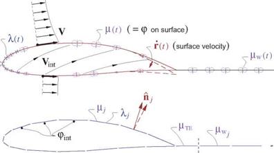
Figure 7.7 shows the velocity field relative to the body, both on the exterior and the interior. These are defined as

V(r, t) = —U — О x r — Г + Vgust + Vp (physical exterior velocity) (7.28)

Vint(r, t) = —U — ° x r — Г + Vgust (nonphysical interior velocity) (7.29)

where only Vp is unknown a priori. The physical flow-tangency requirement on the exterior is

V ■ A = 0 (7.30)

so that the source sheet strength is

which is known and thus can be explicitly specified for each point on the body surface.

If we now specify a zero interior potential, pint = 0, the doublet sheet strength then becomes the physical external perturbation potential p, while on the wake it represents the physical jump др.

F = P – Pint = P (7.32)

Fw = Др (7.33)

Wake convection

Figure 7.7: Body-relative exterior and interior velocities represented by body motion, gust field, and surface source and doublet sheets, shown in top figure. Panel discretization of the sheet strengths is shown in the bottom figure.

The zero interior potential is imposed via Green’s identity

v™ = d5 + + i/AfwVG)’n d5w = 0 (734)

which after evaluation on the paneled geometry becomes the following matrix equation for the unknown surface-panel doublet strengths Fj.

Aij Fj = – Awj Fwj – Bij Aj (7.35)

The trailing edge wake panel strength at each spanwise location is an unknown, but is related to the two top and bottom surface strengths at the trailing edge at that same location.

FwTE (FJTE )u + (FjTE )l (7.36)

This is equivalent to a Kutta condition.

The unsteady solution proceeds in a sequence of time steps, with the following operations performed at each time step:

1. Set the source panel strengths A j from the known Vint (r, t).

2. Set all the wake-panel doublet strengths FWj- from the previous time step, by convecting Fw without change along Va, according to the zero wake-load condition.

DPw _ „

Df

A common approximation made here is to assume

V ^ -(U + Oxr)

which is computationally simpler and much less expensive to evaluate.

3. Wake convectionEvaluate the righthand side in (7.35) using the known Aj and pw.
4. Solve linear system (7.35) for pj, using the same LU-factored A. matrix for all time steps.

5. Using pj, pWj, A j, evaluate ф, Vp, V on surface, compute pressure and airloads.

For a much more detailed description of the necessary calculations see Katz and Plotkin [4].

The 3D unsteady panel method described above is quite general, but provides little insight into unsteady flow behavior except via numerical experimentation. Hence we will next consider simplified models of several specific unsteady flows of interest. Suitable approximations will be used as needed to obtain more concise semi-analytical results for unsteady aerodynamic forces and moments.

Unsteady Panel Method

Standard panel methods which solve the steady potential flow problem can be extended to the unsteady case. The source+doublet panel method will be used here to illustrate these necessary modifications.

3.1.3 Sources of unsteadiness

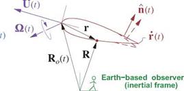
Подпись: Figure 7.5: Typical sources of unsteadiness in an aerodynamic flow are unsteady body motion U(t), O(t), unsteady body deformation n(t), r(t), and a spatially-varying or unsteady atmospheric velocity field Vgust(R,t).
Подпись: Vgust ( R >
Unsteady Panel Method

Figure 7.5 shows the possible origins of flow unsteadiness in an aerodynamic flow which must be captured by any general unsteady flow solution method. These are further described below.

Body motion

One possible source of unsteadiness is unsteady rigid-body motion. This is defined by the specified velocity and rotation rate U(t) and Q(t) introduced in the body-point velocity definition (7.11).

Gust field

Unsteady flow can also be caused by a nonuniform atmospheric motion or “gust” velocity field Vgust(R, t) which is specified. The instantaneous Earth position of any body point r on the aircraft is

R(r, t) = Ro(t) + r

where Ro is obtained by integrating U in time, as described in Chapter 9. The gust velocity at the body point r is then

VgUSt(r, t) = VgUSt(R(r, t),t)

where Earth/body axis conversions using the body Euler angles would be used, as described in Section 9.4. These are obtained by integration of the aircraft rotation rate O(t). In reality, any such gust field will be modified by the presence of the body, but for the typical gust field which has long variations relative to the body size this effect will be small and is generally neglected. This is consistent with classical thin airfoil approximations.

Body deformation

The third cause of flow unsteadiness is a time-dependent body geometry with local velocity r, such as an oscillating flap or a flapping wing. If the deformation of the motion is small, its effects can be approximated by holding the geometry fixed, but still using the actual surface velocity r and normal vectors П when forming the flow-tangency condition.

Unsteady Flow Categories

As derived above, unsteady potential flow introduces three basic new effects not present in steady flow: unsteady Vp ■ n due to body motion U(t), O(t), the additional pdp/dt term in the Bernoulli equation for the pressure, and the generation of shed vorticity yshed. Only some of these effects may be important in any given situation, giving a natural categorization of unsteady flows summarized in Table 7.1.

Table 7.1: Unsteady flow regimes and retained or discarded effects

d(Vp ■ n)/dt

pdp/dt

yshed

Steady

0

0

0

Quasi-steady I

V

neglected

neglected

Quasi-steady II

V

neglected

estimated

Unsteady

V

V

V

The quasi-steady approximation is employed for defining the aerodynamic loads in flight in Chapter 6, where the unsteady forces on a maneuvering aircraft are assumed to be the same as those in steady flight at the same instantaneous flight condition defined by the parameters а, в, p, q, r. In the “Quasi-steady II” case a slight refinement is made by estimating the shed vorticity effects via the additional a parameter.

Potential Jump of Unsteady Vortex Sheet

Подпись: Ф/-
Potential Jump of Unsteady Vortex Sheet

The physical zero pressure jump requirement across a vortex sheet was combined with the steady Bernoulli equation in Section 5.4 to obtain the convection condition (5.15) for the potential jump. For the unsteady case this needs to be re-examined because of the additional term in the unsteady Bernoulli equation (7.19). We therefore consider an unsteady vortex sheet shown in Figure 7.3 which has separate potentials and velocities on its upper and lower sides. The vortex sheet can represent either a thin lifting surface or a wake.

Figure 7.3: Perturbation potential isolines and airfoil-frame velocities above and below an unsteady vortex sheet, on the airfoil and on the wake.

As in the steady case, a thin unsteady wake has the same physical requirement of a zero static pressure jump Ap = pi — pu across it. Taking the difference of the unsteady pressure expression (7.20) between a lower and upper point across the sheet, and setting the result to zero gives

Ap = 0 ->• I (V„-V„ – V/ • V/) + (фи – фі) = 0

5 (V„ + V) • (V„ – V/) + (фи – Фі) = о

Va -V (Ap) + (alp) = 0 (7.21)

where Vu, Vi are the upper and lower Vrei velocities, Va is the average sheet velocity

У а = l2 (V„ + V)

and V() is the surface gradient within the sheet. Note that (7.21) reduces to the earlier steady-flow potential jump result (5.15) if we set (a p) = 0.

3.1.1 Potential-jump convection

Potential Jump of Unsteady Vortex Sheet Подпись: 0 0 Подпись: (on wake) (7.22)

The unsteady wake zero pressure jump condition (7.21) can be rewritten as a substantial derivative.

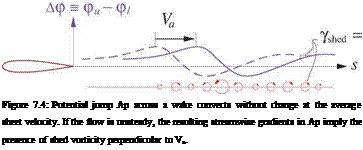
Equation (7.22) implies that the wake potential jump Ap(s, e,t) = pu—pi, set initially at the trailing edge by the Kutta condition, convects unchanged at the sheet velocity Va, as sketched in Figure 7.4.

3.1.2 Shed vorticity

From Figure 7.3 we see that the wake sheet has a tangential velocity jump Vu — Vi = V (Ap), which corresponds to a vortex sheet of the following strength.

Potential Jump of Unsteady Vortex Sheet

дАф

Подпись:ds

The trailing vorticity is the streamwise component of this 7 vector, and the shed vorticity is the transverse component. Choosing the s coordinate to be parallel to Va,

Подпись: (7.24)V0

|Va|

gives the following explicit definitions of the trailing and shed vorticity components.

Ytraii = s ■ 7 (7.25)

Yshed = (sX7) • n = s-V(Ap) = ^7 (7.26)

Comparing equation (7.26) with (7.21) together with the s definition shows that Yshed can be alternatively given by the time rate of Ap.

Подпись: (7.27)(лр) J = 0 , steady flow

|Va| =0 , unsteady flow

Shed vorticity is therefore present only in unsteady flows, and is a major complication in the formulation of unsteady potential flow calculation methods.

Pressure calculation

Подпись: dt Подпись: 2 Подпись: P Подпись: + gz = C Подпись: (7.14)

Chapter 1 gave the derivation if the unsteady Bernoulli equation (1.105) for incompressible flow:

Pressure calculation Подпись: (7.15)

Here we have V2 = |Vp|2, and we will also absorb the hydrostatic term gz into р/р, as described in Section 1.9.3. The integration constant C can be evaluated at any point where the pressure and velocity are known, such as at infinity where p = pL, and where the fluid is at rest so that all p derivatives vanish.

It’s essential to note that (7.15) as written applies only in an inertial frame of reference, since it was ul­timately derived from the momentum equation (1.86) for which we set f to be gravity, omitting any non­inertial forces. This is why we chose U2 = |Vp|2, and not U2 = |Vrei|2- Furthermore, the time derivative dp/dt must be performed at a spatial point which is inertial, meaning that this point is either stationary (VL = 0) or at most translating with uniform speed (VL = 0) relative to Earth. Specifically, the time deriva­tive must not be performed at a point fixed on an accelerating or rotating body.

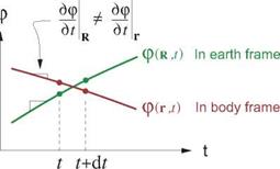
A practical complication here is that because the solution to the potential-flow problem as formulated above is given in the body coordinates in the form p(r, t), its explicit time derivative is at fixed r which is not an inertial point. However, we require a time derivative at fixed R which is inertial. The distinction between the time derivatives in the two frames is shown in Figure 7.2.

Pressure calculation

Figure 7.2: Potential-field time variation at a point R fixed in the Earth frame, and another point r fixed in the body frame. At the moment when the points coincide, the p and Vp values in the two frames are equal, but the time derivatives dp/dt are not.

Pressure calculation Подпись: U + О x r

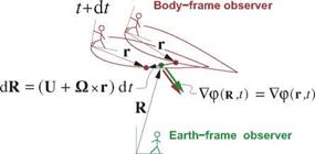
To perform the frame conversion, we first note from Figure 7.1 that positions in the two frames are related by the correspondence function R(r, t) which obeys

which can then be used to relate time derivatives in the two frames. Considering the potential to be in the form p(R(r, t),t), we obtain its time rate in the body frame via the chain rule,

Подпись: dp dp + dp OR dp ~dt r = to R Ш t to r = to Подпись: P =Подпись: + Vp ■ (U + Oxr)Подпись: R(7.16)

Подпись: R Pressure calculation Подпись: (7.17)

where dp/dR is just a more intuitive way to write the spatial gradient Vp in this context. Relation (7.16) then gives the potential’s time-rate in the Earth frame entirely in terms of quantities in the body frame.

Pir,*) = Poo ~ p |Vtp|2 + pVp • (U + Oxr) – pp

Pressure calculation

The pressure can now be expressed using the unsteady Bernoulli equation (7.15) applied in the frame of the Earth-based observer in Figure 7.2:

U = —V О = 0

p = 0

in which case (7.20) reduces to the familiar steady Bernoulli equation.

P(r, t) = Poo + ЗРК2 – 5PlVrel|2

. Governing Equations for Unsteady Potential Flow

Figure 7.1: Positions and velocities seen by an Earth-based observer, and by an onboard observer.

The body’s motion is defined by the velocity U(t) of some chosen reference point on the body, and by the body’s rotation rate O(t). An arbitrary point P on the body has location rp relative to the reference point, and Rp relative to the ground observer. This point’s velocity relative to the ground observer is then

Up = -^ = U + Пхгр (7.11)

which is the same as equation (6.3) considered earlier. The fluid velocity as seen by the ground observer is Vp as defined previously. The local fluid velocity seen in the local body frame at point r is then obtained by subtracting the body frame’s local velocity.

Подпись: (7.12)Vrei(r, t) = Vp — (U + Ox r)

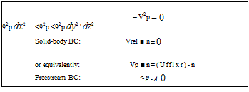
The field equation and boundary conditions for the perturbation potential p(r, t) are

Подпись: 92p dx2 <92p <92p dy2 ' dz2 = V2p = 0 Solid-body BC: Vrel ■ n = 0 or equivalently: Vp ■ n = (Ufflxr)-n Freestream BC: <p -A 0 (7.13)

which must all instantaneously hold for each instant in time. The time dependence arises through the body motion U(t) and O(t), and possibly also through atmospheric motion and body deformation as will be described later.

Unsteady Potential Flow

The Helmholtz vorticity transport equation (1.95) dictates that aerodynamic flows have zero vorticity ev­erywhere except in thin viscous layers adjacent to a solid body and in its trailing wakes. This conclusion remains valid for unsteady flows.

ш = Vx V = 0 (outside viscous layers) (7.5)

Furthermore, the low-speed continuity equation is unchanged in the unsteady case,

а = V – V = 0 (7.6)

so that the velocity field still has zero divergence everywhere in the flow interior. The overall conclusion is that the physical constraints on the vorticity and source distributions are the same in both steady and unsteady low speed flows. The instantaneous velocity field outside the viscous layers (or the entire Equivalent Inviscid Flow, introduced in Chapter 3) can still be represented by the perturbation potential P(r, t).

V(r, t) = Vp (7.7)

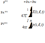
If source sheets and doublet sheets are used as in most panel methods, then the unsteady potential can be expressed explicitly via the usual superposition integrals, which now have unsteady sheet strength distribu­tions.

Подпись:Подпись:Подпись: | r — r' | n • (r —r') I r — r'l3 (7.8)

Подпись: ds d£(7.9)

Подпись: ds dl(7.10)

Unsteady Aerodynamic Flows

This chapter will examine the general low-speed unsteady potential flow problem. Specifically, we will revisit flow-field modeling in the unsteady case, and also the unsteady Bernoulli equation for the unsteady pressure. The special case of unsteady airfoil flows will be examined in more detail.

3.1 Unsteady Flow-Field Representation

Chapter 2 defined the source density and vorticity as the divergence and curl of the velocity field.

a = V-V ш = VxV

These involve only spatial derivatives and hence apply instantaneously even if V is changing in time. Simi­larly, representation of the velocity field via its source, vorticity, and boundary contributions

V(r, t) = V + V + Vb

involves only spatial integrations, and likewise applies instantaneously. An unsteady flow can therefore be represented in the same manner as a steady flow, but all the relevant quantities will now depend on time as

well as space.

V(r, t)

= 4п111а{Г’Л) r-rfdX’dy’dZ’

(7.1)

Vw(r, t)

– 4vr US dx’dy’dz’

(7.2)

Vb

= V» (observer moving steadily in airmass)

(7.3)

Vb

= 0 (observer fixed in airmass)

(7.4)

We see that the unsteadiness of the velocity field is captured entirely by the time dependence of the source and vorticity fields a(r, t), ш(r, t). Furthermore, since the lumping process is strictly spatial, as in the steady case the integrals above can be simplified using the lumped unsteady sheet strengths X(s, e,t), 7(s, e,t), line strengths Л(г, і), V(e, t), or point strengths £(t). For free vorticity such as in trailing wakes, an alternative approach is to move the vortex points rather than change the singularity strengths. In that case (7.2) is still valid, but now the integration points Г are functions of time.

In typical steady flow applications so far we have assumed that the body is fixed, so that the last boundary – condition component Vb is the freestream velocity V». In unsteady flow applications it is often more convenient to represent the body motion explicitly via its velocity U(t) and rotation rate O(t). In this case we choose Vb = 0, and V then represents the “perturbation velocity,” which is what’s seen by an observer stationary with respect to the airmass.

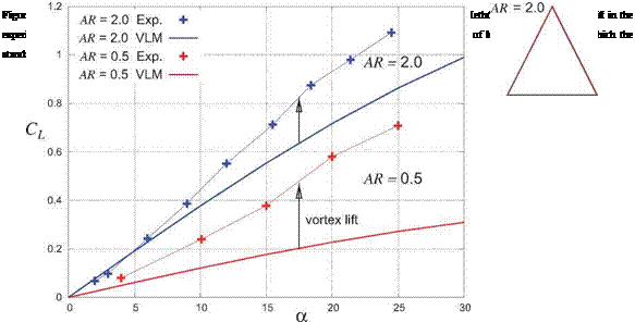
Vortex lift models

Polhamus [51] has developed a method for estimating vortex lift based on the leading-edge suction concept. In this formulation the leading edge suction force magnitude is obtained from the slender-body flow solution for a flate plate, corresponding to the geometry in Figure 6.12 with R = 0. This force is then applied normal to the surface rather than tangential to the surface, which in effect rotates it by 90° about the leading edge line. The equivalent formulation for general lifting surface geometries uses the leading edge suction force defined by equation (6.23), but applied in the normal direction.

/ "П 2

FSle = — pC n (at sharp leading edge) (6.80)

This rotation of the leading edge suction force from t to n models the boundary layer vorticity lifting off the surface and forming a free vortex sheet above the surface, as sketched in Figure 6.13 on the bottom right. The force rotation clearly increases the lift, and thus captures the vortex lift contribution. The lift increase reported by Polhamus matches experimental data fairly well.

Vortex lift models

The rotation of the leading edge suction force changes its direction from partly forward to partly aft, which significantly increases the drag. This effect on drag was also examined by Polhamus [52], with the conclu­sion that the added drag behaves much like induced drag from the added lift.