Category Flight Vehicle Aerodynamics

Physical Requirements

The velocity field V(r) description (2.3) via the a and ш fields is purely mathematical, and in fact can be used to represent any vector field whose divergence and curl arc known. In the case of fluid flow, however, physical requirements strongly dictate and frequently simplify the magnitudes and distributions of the a and ш fields. These physically-dictated simplifications, discussed in this section, are in fact what makes this flow-field representation approach so effective in aerodynamics. Also discussed will be the flow categories where the physical constraints do not provide significant simplification.

2.2.2 Sources in incompressible flow

In the case of effectively-incompressible flow, the low-speed continuity equation (1.85) demands that a and hence А, Л, and £ are all zero within the flow-field.

V-V = 0

^ a = А = Л = £ = 0 (within flow-field) (2.57)

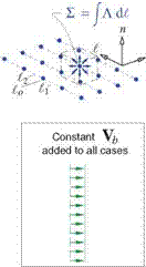
However, it is perfectly acceptable to have nonzero fictitious sources outside the physical flow-field, either within a body or on a flow boundary. Figure 2.10 shows impermissible and permissible uses of sources to represent an incompressible velocity field. The rightmost figure shows the typical use of image singularities to represent the effect of a solid wall boundary.

Physical Requirements

Permitted
Velocity-Potential Integrals

2.2.1 3D potentials

Velocity-Potential Integrals Подпись: (2.43) (2.44) (2.45) (2.46)

The velocity fields of the

Velocity-Potential Integrals

Velocity-Potential Integrals

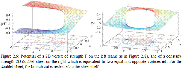
One complication here is that the arctan( ) polar angle can contain some arbitrary multiple of 2n. This requires introduction of a branch cut extending from the vortex point out to infinity in some direction, as shown in Figure 2.8. The angle jumps by 2n and the potential jumps by Г across the branch cut.

Подпись: 1 2vr Velocity-Potential Integrals Подпись: (2.56)

The branch cut also appears for a doublet sheet, which has the following potential in 2D.

Подпись: Figure 2.9: Potential of a 2D vortex of strength Г on the left (same as in Figure 2.8), and of a constant-strength 2D doublet sheet on the right which is equivalent to two equal and opposite vortices ±Г. For the doublet sheet, the branch cut is restricted to the sheet itself.

However, the branch cut now is only on the doublet sheet itself. It does not need to extend to infinity like with a vortex, unless the doublet sheet itself extends to infinity. Figure 2.9 compares the branch cuts of a point vortex and a doublet sheet, the latter being equivalent to two point vortices of opposite sign.

Integral Velocity / Vorticity-Source Relations

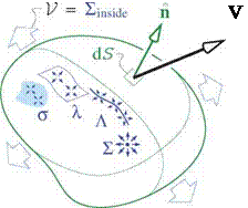
Consider the volume flow rate V outward through a closed surface, defined as the area integral of the normal velocity component over the surface, as shown in Figure 2.7 on the left.

v=1

P V ■ A dS = V – V dV

inside

(2.39)

= a dx dy dz +

inside

A ds dl +

inside

Л d^ + V = Vinside

inside

(2.40)

Integral Velocity / Vorticity-Source Relations Подпись: Y Подпись: V Подпись: Г

The second form in (2.39) follows from Gauss’s theorem, for which the volume integral is evaluated over the volume inside the surface. The alternative forms in (2.40) follow from the source density definition (2.1) and the various lumped source sheet, line, and point definitions, and are evaluated over all the source singularities present inside the volume bounded by the surface. The overall result is that V for a closed surface is equal to the sum of all the point sources or integrated volume, sheet, or line source distributions inside.

Figure 2.7: Volume outflow V through closed surface (left) is equal to the total integrated source strength of all source density, sheets, filaments, and points inside. Circulation Г over closed circuit (right) is equal to the total circulation of all vorticity, vortex sheets, and vortex filaments enclosed or encircled by the circuit.

Next consider the circulation Г about a closed circuit, defined as the line integral of the tangential velocity component around the circuit, indicated in Figure 2.7 on the right.

Подпись: (2.41) (2.42) Г = V ■ dl = (VxV) ■ A dS

enclosed

= Ш ■ A dS + Y ■ Ads + Г = Tendosed

enclosed enclosed

The second form in (2.41) follows from Stokes’s theorem, for which the area integral is understood to be evaluated over any surface bounded by the contour, with A being the unit normal on this surface. The alternative forms in (2.42) follow from the vorticity definition (2.2) and the various lumped vortex sheet and line definitions. The overall result is that the circuit circulation Г is equal to the total strength of all the integrated vorticity, vortex sheets, and vortex filaments enclosed by the circuit. Any vortices outside the circuit have no contribution to Г.

Equivalence of Vortex and Doublet Sheets

Equivalence of Vortex and Doublet Sheets Подпись: 47Г. 1 2vr Equivalence of Vortex and Doublet Sheets Equivalence of Vortex and Doublet Sheets Подпись: (3D) (2.37) (2D) (2.38)

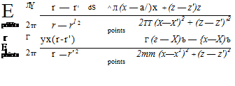
The vorticity streamfunction f(sY) can also be interpreted as the normal-doublet sheet strength. An area element ds dt of the doublet sheet in effect has an infinitesimal 3D doublet of strength dKn = f ds dt, oriented along the normal direction. In two dimensions, the element ds of the sheet has an infinitesimal 2D doublet of strength dKn = f ds. The resulting velocity fields in 3D and 2D are

which are the same as the VY(r) fields of the equivalent vortex sheets given by (2.16) and (2.24). This equivalence can be verified with some effort by substituting 7 = n xVp into (2.16) or (2.24) and integrating by parts.

Equivalence of Vortex and Doublet Sheets Equivalence of Vortex and Doublet Sheets

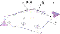
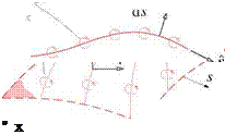
Figure 2.5 illustrates the doublet-sheet/vortex-sheet equivalence for 3D and 2D sheets. In general, a linearly – increasing p is equivalent to a constant-magnitude 7, and vice versa. At the edge of the doublet sheet, p(s, e) in effect has a step change to zero. Here Vp and the corresponding 7 have an impulse, which is equivalent to a vortex filament of strength Г = p along the sheet edge. Figure 2.6 shows the constant-strength doublet sheet case.

Подпись: Г = p Equivalence of Vortex and Doublet Sheets Equivalence of Vortex and Doublet Sheets
Equivalence of Vortex and Doublet Sheets

Figure 2.5: Equivalence between normal-doublet sheet and vortex sheet away from edges, for 3D and 2D cases. The doublet and vortex sheets have the same velocity fields.

Figure 2.6: Constant-strength normal-doublet sheet with edges, and the equivalent vortex filaments, for 3D and 2D cases.

Because the elimination of the zero-divergence requirement for 3D vorticity is such a great simplification, doublet sheets are heavily favored over vortex sheets in all common 3D panel methods. However, the zero – divergence constraint does not appear in 2D, with the result that vortex sheets tend to be favored over doublet sheets in 2D panel methods. For an extensive review and implementation details of various 2D and 3D panel methods see Katz and Plotkin [4].

In the subsequent discussions and applications here, we will employ either vortex or doublet sheets as most appropriate. In particular, constant-strength doublet panels which are equivalent to vortex rings will be used for 3D configuration analyses in Chapters 5 and 6.

3D Vortex Sheet Strength Divergence Constraint

Although vortex sheets have many attractive properties for representing aerodynamic velocity fields, their main drawback in 3D is that the vortex sheet strength 7 is a vector whose components are not entirely independent. The complication stems from the vorticity field having identically zero divergence due to its curl definition.

Подпись: (2.31)V ■ ш = V-(VxV) = 0

3D Vortex Sheet Strength Divergence Constraint 3D Vortex Sheet Strength Divergence Constraint 3D Vortex Sheet Strength Divergence Constraint

Using the locally-cartesian stn sheet coordinates, the resulting divergence of a lumped vortex sheet strength 7 can then be determined by lumping the divergence of the vorticity.

The surface-gradient operator V definition simply excludes the n component. The integral J dwn/dn dn vanished since the n,n2 endpoints are assumed to be outside the vorticity layer where wn = 0.

3D Vortex Sheet Strength Divergence Constraint

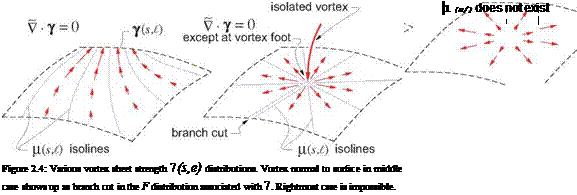
Equation (2.34) is the key constraint on the 7 vector. In effect, the 7 vectors in the vortex sheet must resemble the velocity vectors in 2D incompressible flow which also have zero divergence. Figure 2.4 shows three vortex sheet strength 7(s, e) distributions. The second case has a nonzero (singular) divergence at one isolated point, which requires a vortex filament to be attached at that point normal to the surface. The third case is nonzero 7 divergence everywhere which is impossible given the vorticity-lumping assumptions.

Подпись: or Подпись: Ys Подпись: Y djx dt 3D Vortex Sheet Strength Divergence Constraint Подпись: (2.36)

An effective way to ensure that 7 has a zero surface-divergence is to introduce a scalar function ^(s, e), which defines 7 via f’s surface gradient, rotated 90° about the surface unit normal.

Подпись: 'V • 7 Подпись: дъ dj/e ds + dt Подпись: d2F d2F ds dt dt ds

Note that any 7 defined in this manner automatically has zero surface divergence

so that (2.33) ensures that wn = 0. Conversely, if there is a point or line where concentrated vorticity is shed with wn = 0, such as along the trailing edge of a lifting wing, then f(s/) must be discontinuous on a branch cut extending from the point, as shown in Figure 2.4. Such a branch cut must be accounted for in any calculation method which seeks to determine f(s/). In a case of a lifting wing, the branch cut is typically placed all along the trailing edge from which vorticity is shed into the otherwise irrotational flow.

One conceptually useful interpretation of f(s/) is that it’s a streamfunction for 7(s, e), guaranteeing its zero divergence just like the conventional streamfunction ф(х, х) guarantees zero divergence of V(x, z) in two­dimensional flow. And just as streamlines of V follow constant-^ lines, the vortex lines parallel to 7 follow the constant-F lines on the vortex sheet, as shown in Figure 2.4.

2D forms

This chapter has so far treated only the general three-dimensional case. All the concepts remain largely unchanged in two dimensions. The main simplification in 2D is that the vorticity, vortex sheet strength, and circulation vectors have only one component in the y direction into the x-z plane, and hence can be treated as scalars.

ш = ш y

7 = Y У (2.22)

Г = Г У

2D forms Подпись: (2.23) (2.24) (2.25) (2.26)

The velocity superposition integrals then take on the following forms in two dimensions.

2D forms 2D forms Подпись: (2.27) (2.28) (2.29) (2.30)

Their simplified lumped versions follow from the same lumping procedure as in 3D. The sheet coordinates in the x-z plane are now sn, and t is into the plane and parallel to y.

Points

Подпись: VJ (r) ~ VS(r) Points Подпись: £ = Подпись: £2 Л(£) d£ £1 Подпись: (2.21)

The source filaments can be subjected to one more lumping step by dividing the £ coordinate into some number of intervals from £1 to £2, and lumping Л(£) over each interval into a point-source strength £. The filament integrals then become a sum of relatively simple algebraic expressions over the point sources.

The resulting velocity field is now even more singular than for the filaments, varying as |Vh| 1/Ar2

where Ar = | r — r’ | is the distance to the point.

Vortex filaments could be lumped into point point vortices or “vortons” in the same manner as the source filaments. However, in addition to having the |V| ~ 1/Ar2 singularity, the resulting velocity field is not exactly irrotational in the vicinity of each vorton. Hence, if perfect irrotationality is required away from the singularities, then equations (2.20) and (2.21) constitute the simplest possible velocity field representation via vortices and sources.

Lines

The second lumping stage consists of dividing the s coordinate into some number of short intervals, and assuming that r/(s, i) — r'(so, i) where so is some representative s value on each interval. We can then integrate A or y across each interval from si to s2, thus defining the line or filament strengths Л(і) or Г(і). Each surface integral then becomes a summation over a number of simpler line integrals along the remaining

Lines Lines

filament coordinate £, with r'(£) now denoting the integration points on the filament. Here we also assume that £ is chosen to be aligned locally with the 7 vector direction, as indicated in Figure 2.3.

The resulting velocity fields Va and Vr defined above are now strongly singular at the filaments, varying as |Va|, |Vr| ~ 1/Ar where Ar is the nearest distance to a filament. The magnitude of these singularities depends on the width of the s intervals for the lumping integration and the resulting line spacing, which can be chosen arbitrarily. A fine sheet subdivision into many weak filaments proportionally reduces the singularities, giving a smoother velocity field at any given distance from the filament-approximated surface.

Подпись: Г d£ vr(r) Подпись: Г dl ^ Г f dl x (r — r') ^ 47Г J Ir-r'l3 lines Подпись: (2.19) (2.20)

The vortex-filament velocity definition (2.18) can be simplified somewhat by applying the Helmholtz vortex law [2] which states that the magnitude of Г cannot change along the filament. In addition, since the £ coordinate was chosen to be aligned with 7, the lumped Г must be parallel to the filament element vector dl at each location. We can then convert the Vr definition (2.18) into the familiar Biot-Savart integral.

Note that the integral itself is purely geometric, and can be evaluated without knowing the filament circula­tion Г a priori.

Sheets

In the first simplification stage we neglect the kernel function’s n dependence by assuming a representative integration point r'(s, i,n) — r'(s, e,no) at some fixed no location, indicated in Figure 2.3. The simplified kernel function can then be removed from the n integral, allowing the a or ш distribution to be integrated or lumped in n across the layer thickness from щ to? г2, thus defining the sheet strengths Л(s, e) and The

volume integrals in the velocity superposition (2.3) then become the simpler surface integrals over the sheet coordinates s and l, with r/(s, i) now denoting the integration points on the sheet.

Vj (r) — VA(r) =

si

A(s, i) =

П2

a(s, i,n) dn ni

(2.15)

Vw(r) — Vy (r) =

si

b*,;~rfdsd< :

Y(s, i) =

П2

ш(s, l,n) dn

ni

(2.16)

The resulting velocities Va and VY are now discontinuous across the sheets, but this does not cause any problems in practice. Note also that outside the original source or vorticity volume, Va is very nearly the same as the actual V<t, and VY is very nearly the same as the actual Vu, as Figure 2.3 suggests. Sheets are extensively used in aerodynamic modeling and computation, and will be discussed in more detail later.

Aerodynamic Modeling – Vorticity and Source Lumping

The general velocity field representation (2.3) via the source and vorticity fields is primarily conceptual, since the volume integrals for the Vr and V components are impractical to evaluate in numerical appli­cations. However, the representation (2.3) can be approximated and greatly simplified by the process of lumping, which is based on the approximation that the kernel function is constant along some small interval of one of the s£n coordinates. This allows the source and vorticity volume distributions to be in effect con­centrated into surfaces or sheets, and then possibly further concentrated into lines (or filaments), and then possibly even points. This process, illustrated in Figure 2.3, is the basis of aerodynamic modeling.

Note that at each lumping stage the singularity geometry becomes simplified, but the resulting velocity field becomes more singular and less realistic near the sheet, filament, or point (which is the origin of the name singularity). However, sufficiently far away the actual and approximated velocity fields become the same.

The lumping operation uses the curvilinear s£n coordinates, defined such that s£ lie on the surface of the sheet, filaments, or points, and n is normal to this surface. For simplicity, the curvatures of the s£n coordinate

Aerodynamic Modeling - Vorticity and Source Lumping Aerodynamic Modeling - Vorticity and Source Lumping Подпись: 5

lines are assumed to be sufficiently small so that they form a local effectively Cartesian system. A volume element is then simply ds dl dn, and a surface element is ds dl, so that the Jacobian factors which should appear in these elements are assumed to be unity and hence omitted for simplicity. This approximation does not adversely affect the effectiveness of the lumping concept for most aerodynamic applications.

Figure 2.3: Lumping of source and vorticity volume distributions into sheets and then lines. Source lines can be further lumped into source points. The evaluation of the velocity at any field point r then becomes progressively simplified. Lumping is the basis of aerodynamic modeling.