Category Flight Vehicle Aerodynamics

Velocity / Vorticity-Source Duality

The sheet strengths A and 7 in Figure 2.1 will be shown to be closely related to the source density a and vorticity ш distributions, which can be obtained from the velocity field by taking its divergence and curl.

a(r) = V-V (2.1)

ш( r) = VxV (2.2)

Conversely, the velocity field can be obtained from the source and vorticity fields via definite volume inte­grals over the entire flow-field. This in effect reverses the divergence and curl operations, as discussed by Batchelor [2] in some detail. These reciprocal operations are illustrated in Figure 2.2, and given as follows.

V(r)

= Vo + V + Vb

(2.3)

where Vo (r)

– iJIIa{”’ r-rf dX’iV’d‘

(2.4)

Vw(r)

= 4ТГ j®^(r,)X|r-r’|3 dx>dy>dz>

(2.5)

Vb

= Vo (for unbounded external flow)

(2.6)

Velocity / Vorticity-Source Duality

Figure 2.2: A flow velocity field V(r) shown on the left can be used to define the source and vorticity fields a(r) and ш(г) shown on the right, and vice versa. Boxes contain reciprocal conversion relations from one description to the other, with Vo – and Vu defined by equations (2.4) and (2.5).

The infinitesimal volume element dx’dy’dz’ at the integration point location r’ with source density a(r’) and vorticity w(r’) has contributions to the total V(r) at the field point at r. The source contribution dVo – is parallel to the connecting vector (r — r’), whose explicit definition and magnitude are as follows.

r — r’ = (x—x’) x + (y—y’) y + (z — z’) z (2.7)

|r-r’| = J{x-x’]2 + (y-yO2 + (z-z1)2 (2.8)

The vorticity contribution dVw is perpendicular to both (r — r’) and ш.

The last velocity component V/, in (2.3) is the part of V which has both zero divergence and zero curl everywhere in the flow-field, and hence cannot be represented by a or ш within the flow-field. In the typical external aerodynamic flow extending to infinity, V is a constant field, and equal to the freestream velocity as given by (2.6). In the more general case, such as flow near a wall or inside a wind tunnel, Vb is not a constant, but it can be uniquely determined as follows.

Since Vx Vb = 0, this velocity must be expressible as a gradient of some scalar potential function Фь (r).

Vb = Уфъ (2.9)

Setting the divergence of this Vb to zero as required by its definition gives

V – Vb = V – ^фъ) = 0

V2фb = 0 (2.10)

so that Фь must satisfy the Laplace equation (2.10). This will have a solution everywhere inside the flow-field if appropriate boundary conditions are specified on all the flow-field boundaries. The boundary conditions are case-dependent, and some typical examples are given below.

Фь = Vo ■ r = uo x + vo y + wo z (at distant boundary) (2.11)

дфb/dn = — (Vr + V) ■ n (at solid-wall boundary) (2.12)

For simple flat internal-flow boundaries such as wind tunnel walls, Vb can be alternatively obtained using the method of images. Many examples are given in Chapter 10.

It’s useful to note that the Vr superposition integral (2.4) has the form

Vr(r) = a(r’) K(r-r’) dx’ dy’ dz’

(2.13)

1 r — r’

K(r, r’) — K(r-r’) — /|3

4n | r—r’|3

(2.14)

where K is the kernel function which is strictly geometric, in that it depends only on the coordinates of the field point r and the integration point r’. More specifically, it depends only on the connecting vector r — r’ between the two points. The specific kernel function (2.14) can be interpreted as the velocity field V(r) of a unit-strength point source located at r’.

Flow-Field Modeling

This chapter will address the specification or description of the velocity field of an aerodynamic flow, in terms of its associated source and vorticity fields. Effective simplifications and idealizations of the flow – field will also be developed within this flow description approach.

2.1 Vector Field Representation Methods

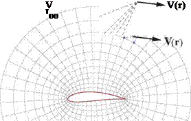
The majority of computational methods for fluid flow prediction use one of two different methods to define the velocity field V(r). These are sketched in Figure 2.1, and described as follows.

1) A grid method where discrete values Vj are defined at the nodes of a grid which fills the entire flow-field. A suitable interpolation scheme is used to interpolate these values to obtain V(r) at any position vector point r within the grid. This is the approach used by modern Computational Fluid Dynamics (CFD) methods which solve the Full-Potential equation, the Euler equations, or the Navier-Stokes equations.

2) A singularity method which uses the velocity fields of source and vortex sheet strengths Aj, 7j which are defined in limited regions of the flow-field, typically at solid surfaces or other boundaries. Weighted integration or summation over these source and vortex strengths, together with an additional freestream velocity V, is used to obtain V(r) at any point in the flow-field. This approach is used by Vortex Lattice and Panel methods for potential flows.

Подпись: Grid Method

Flow-Field Modeling

Singularity Method

Figure 2.1: Grid and singularity methods used to represent a velocity vector field V(r).

This chapter will focus on the singularity method 2). In addition to being the basis of Vortex Lattice and Panel flow calculation methods, this flow-field representation is also the basis of many useful engineering approximations, including the formulation of outer boundary conditions in grid-based CFD methods. It also provides an intuitive and physical understanding of aerodynamic flows and general flow behavior, and hence is useful even if the grid-based CFD methods are being employed.

Aerodynamic Flow Categories

The various types of high Reynolds number aerodynamic flows can be categorized by the Venn diagram shown in Figure 1.16. All have mostly-irrotational flow with relatively thin boundary layers and wakes. Hence, much of the book will focus on potential flow modeling and prediction. Most aerodynamic bodies are also adiabatic, so the treatment of viscous flows here will focus on adiabatic boundary layers.

Viscous (High Reynolds Number)

Подпись: Low Speed M 2<< 1 Low speed BLs with heat transfer Подпись:

Подпись: Adiaba tic qv = 0 qn = 0 High speed BLs without heat transfer
Подпись: Incompressible p = constant

High Speed Boundary Layers with heat transfer

Подпись: Incompressible potential flows

Подпись: Compressible potential flows

Isentropic, Irrotational
ю= 0

Figure 1.16: Aerodynamic flow categories. This book will focus primarily on potential flows and low speed adiabatic boundary layers, which are shown shaded.

Aerodynamic Flow Categories

Bernoulli equation

If the flow is irrotational, then the velocity must be the gradient of a velocity potential ф(r, t).

V = Vф (1.102)

If f is the gravitational force per unit mass as is usually case, then we also have

f = —g Vz (1.103)

where g is gravity’s acceleration and z is the vertical height. With these assumptions, and also assum­

ing that the flow is effectively inviscid so r can be neglected, the alternative form of the compressible or incompressible momentum equation (1.91) or (1.86) simplifies to

V4 + Jv(V2) = – gVz – ^ (1.104)

dt 2 p

which can be integrated if we make suitable assumptions about the density p.

Incompressible Bernoulli equation

Подпись: dt Подпись: 2 Bernoulli equation Подпись: (1.105)

Assuming p = constant and integrating (1.104) gives the general Incompressible Bernoulli equation

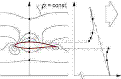
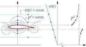
Figure 1.15: Overall pressure p decomposed into hydrostatic and dynamic components — pgz + p’.

where C is some integration constant. It is convenient to decompose the pressure p into a hydrostatic pressure field —pgz and a remaining part p’ associated with only the fluid motion, as shown in Figure 1.15.

p = —pgz + p’ (1.106)

This effectively eliminates the gravity term from the Bernoulli equation (1.105).

Подпись: (1.107)

Bernoulli equation Bernoulli equation

% + + t = c

dt 2 p

From now on we will denote p’ simply as “p ” with the understanding that it really represents the deviation from the known hydrostatic pressure —pgz. The latter provides a buoyancy force equal to the displaced fluid’s weight, which directly adds to the hydrodynamic force from p’ and surface viscous stresses.

Fbuoyancy = © pgz n dS = pgz dV = pg Vbody z (1.108)

body body

This buoyancy force is usually ignored, notable exceptions being lighter-than-air and underwater vehicles.

This pressure decomposition is not usable for the free-surface flows about surface water vehicles. Here the overall true pressure —pgz + p’ is imposed to be constant on the free surface as a boundary condition, which then results in the generation of surface gravity waves with heights z. These waves influence the velocity field, which in turn influences p’ and hence the wave shapes. Therefore, the hydrostatic and dynamic parts of the pressure field are two-way coupled and cannot be treated separately.

Pc + 2pV* = po-

Подпись: 2 Подпись: (1.109)

For low-speed steady aerodynamic flows, the constant C in (1.107) is most conveniently defined from the known freestream total pressure, giving the most familiar form of the Bernoulli equation.

In this case, the pressure coefficient definition (1.54) also reduces to a relatively simple form.

Подпись:V 2

cr = i-w

It must be stressed that the Bernoulli forms (1.109) and (1.110) apply only where the total pressure is equal to the freestream value.

Compressible Bernoulli equation

Подпись: P Подпись: P о Подпись: p_ Po Подпись: 1/7

An alternative assumption for the density is to use the isentropic relation (1.69)

in which case (1.104) integrates to the compressible version of the general Bernoulli equation.

Подпись: дф . XF2 . ato ( p dt 2 7-І У 'р^ ,2 / m (Y-1)/Y

Подпись: (1.111)+ gz = C

7-1 * r2( V2 2 дф

2 M c2 v2 dt

Подпись: P_ Po Подпись: 7/(7-1) Подпись: (1.112)

Dropping the gravity term as before, and using the freestream to evaluate the integration constant gives the isentropic unsteady pressure formula, with the steady form obtainable by dropping the дф/dt term.

Crocco relation

The d() differentials in the Gibbs relation (1.61) can be taken along a dx interval and then divided by dx to convert them to partial derivatives.

ds dh 1 dp

dx dx p dx

Repeating this along dy and dz intervals, and adding the three results as vector components, gives the gradient form of the Gibbs relation.

TVs = Vh – ^ p

1 p

= у ho – – V(V-V)————- (1.99)

2 p

Combining this with the alternative form of the momentum equation (1.91) gives

dV 1 _

TVs = Vh0 + ^————– Vxw – f – – V • r (1.100)

dt p

which for steady inviscid flow without body forces simplifies to the Crocco relation.

Подпись: T Vs = Vho — V x ш(steady, inviscid) (1.101)

For the steady adiabatic case this explicitly confirms the equivalence between isentropy and irrotationality deduced in the previous section. It is also useful in many applications in which one of the three terms in (1.101) is known explicitly, which then provides an explicit relation between the two remaining terms.

Vorticity Transport and Irrotationality

The behavior of vorticity will be examined by formally taking the curl of the momentum equation (1.36). The manipulations will use the following identities, which are valid for any vector fields a and b.

V(a ■ b) = a ■ Vb + b ■ Va + a x (Vx b) + b x (Vx a) (1.87)

V x (a x b) = a V ■ b — b V – a + b ■ Va — a ■ Vb (1.88)

1.9.1 Helmholtz vorticity transport equation

Setting a = b = V in identity (1.87) gives

^V(V-V) = V’VV + Vxw (1.89)

ш = Vx V (1.90)

where ш is the vorticity. Using (1.89) to replace the V ■ VV term in the momentum equation (1.36) puts it into the following alternative form.

д V 1

– + – V(V. V)-Vxc


Vp V – t

– + –

pp


(1.91)


We now take the curl V x [equation (1.91)], use the identity V xV() = 0, and note that the curl commutes
with the d()/dt operation. The body force field f is also assumed irrotational as is typical, so that Vxf = 0.

^-Vx(Vxu;) = – V(“) xVP + Vx ("^r) (L92)

Next we set a = V and b = ш in identity (1.88) which gives

D(1 /Р)
Dt

where the convective mass equation

Подпись: V-VlDp = D(1 /p)

p Df Df

Vorticity Transport and Irrotationality Vorticity Transport and Irrotationality Vorticity Transport and Irrotationality Подпись: (1.94) (1.95)

and the identity V – ш = V(VxV) = 0, have been used. Substituting (1.93) in (1.92), dividing through by p, and combining and rearranging terms finally gives the Helmholtz vorticity transport equation, with its simpler incompressible form resulting from p and p being constant.

The baroclinic source term Vp x Vp in the compressible Helmholtz equation (1.94) can cause vorticity to appear wherever there are density and pressure gradients present. However, in isentropic flow where the viscous term is negligible the isentropic p(p) relation (1.69) holds, so here the p and p gradients are parallel

Vp = yrVp = 7 – Vp (1.96)

dp p

and therefore the baroclinic term vanishes since Vp x Vp ~ Vp xVp = 0.

The term ш ■ VV on the righthand sides represents vortex tilting and vortex stretching, the latter causing a rotating fluid’s vorticity to intensify when the rotating fluid is stretched by the components of the velocity gradient matrix VV which are parallel to ш itself. However, if ш = 0 to begin with, then this term is disabled, since there is no vorticity to stretch or tilt.

The Helmholtz vorticity equation (1.94) or (1.95) simplifies greatly for most aerodynamic flows. These typically have uniform flow and hence ш = 0 upstream, and their viscous stresses are negligible outside of viscous layers and outside of shocks. In these circumstances (1.94) gives

Подпись: - =0 p ш =0 Подпись: D Df (1.97)

(1.97) with the conclusion being that initial irrotationality persists downstream outside of the viscous layers and shock wakes. These are the same requirements as those for isentropy, discussed earlier and shown in Fig­ure 1.11. Hence we can further conclude that flows which are irrotational are also isentropic, as illustrated in Figure 1.14.

Vorticity Transport and Irrotationality

s = constant ^^ ш = 0

Irrotationality of the velocity field has great implications for flow-field representation and modeling, which will be treated in Chapter 2. It also enables the various Bernoulli relations for the pressure, considered next.

Low Speed and Incompressible Flows

By considering the governing equations and definitions developed earlier, we can estimate the following typical changes д() of various quantities along a streamline, or more precisely along a particle path.

From ideal gas law (1.13):

Y др ~ (7—1) (h дp + p дН)

(1.75)

From momentum equation (1.36):

др ~ —pVдV

(1.76)

From total enthalpy definition (1.18):

дН ~ дН0 — VдV

(1.77)

Eliminating др between (1.75) and (1.76), eliminating дН using (1.77), and noting that V2/h = (7—1)M2 gives the fractional density change only in terms of fractional V and ho changes.

(1.78)

A low speed flow is defined as one with a negligibly small Mach number everywhere.

M2 ^ 1 (low speed flow) (1.79)

If in addition the flow is adiabatic so that ho ~ constant and hence дН0 = 0, then (1.78) implies

Подпись: др p or p < 1

~ constant along particle path, (1.80)

Low Speed and Incompressible Flows Low Speed and Incompressible Flows

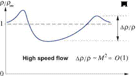
which constitutes an incompressible flow. Figure 1.13 compares typical density variations along a streamline near an airfoil in high speed and low speed flows.

Figure 1.13: In an adiabatic flow, fractional density variations др/р scale as M2 .In the low speed flow case M2 ^ 1 this implies a nearly constant p equal to the freestream value pTO.

For typical aerodynamic flows where the far-upstream density is uniform, the incompressibility result (1.80) becomes the more general statement that the density is constant everywhere in the flow, and equal to the freestream value.

p ~ constant = pTO (incompressible aerodynamic flow) (1.81)

For adiabatic low speed flow where дН0/Н ~ 0, relation (1.77) in addition indicates

Подпись: дН0 . „ о дV — - h-D«v « 1 д/г h

Подпись: (1.82)or h constant

so such flows are also nearly isothermal, and therefore the viscosity p is nearly constant everywhere. In this case the vector identity

V2a + V (V – a)


Va + (Va)T


(1.83)


V-


together with а = V- V = 0, which is the consequence of mass conservation and p = constant, can be used to simplify the viscous momentum term in (1.34) or (1.36) to a Laplacian of the velocity.

Low Speed and Incompressible Flows

p V2V


V ■ T


(1.84)


Low Speed and Incompressible Flows

Overall, the continuity and momentum equations simplify to the incompressible Navier Stokes equations

Подпись: V-V = 0(1.85)

9V

~dt


+ V V2V


+ V – VV


(1.86)


Low Speed and Incompressible Flows

where v = p/p is the kinematic viscosity. The energy and state equations decouple and are no longer needed.

Isentropic relations

Setting ds = 0 in the Gibbs relation (1.61), assuming a calorically-perfect gas with constant cp, and using the ideal gas law (1.13), gives the following three differential equations.

Подпись: (1.67)dp dp у dh

p ^ p 7—1 h

Подпись: P2 Pi Подпись: P2V = //t2V/(7-1} Pi) hi) Подпись: (1.68)

These can be integrated to give the three isentropic relations,

Подпись: Figure 1.11: Valid and invalid paths for the isentropic relations (1.68) between any two points in an aerodynamic flow. In the the isentropic region outside of shock wake and viscous regions the path is arbitrary, since all points there can be also connected with the single freestream state.

where ()i and ()2 are any two states along a particle pathline which is unaffected by viscous stress, heat conduction or addition, or shock losses. For regions whose streamlines are isentropic all the way from far-upstream, points 1 and 2 do not need to lie on the same streamline, as indicated in Figure 1.11.

In steady or unsteady external flows, a common choice for state 1 is the freestream state ()TO, and for state 2 is the state at any point (r, t) in the flow outside of viscous layers or shock wakes, as shown in the upper left of Figure 1.11.

P(r, t) _ ( P(r, t)7 _ / /?.(!•,*) y/(7 1}

Poo V Poo ) V hoo )

(1.69)

This uniquely relates all the thermodynamic variable fields. These relations, when applicable, can be used as replacements for the energy equation or the streamwise component of the momentum equation.

Isentropic relations

Figure 1.12: Isentropic stagnation process from local state 1, to a hypothetical stagnation state 2 denoted by ()o with V =0. This could actually be done by placing a small obstruction in the flow.

Isentropic relations Isentropic relations Isentropic relations Isentropic relations Isentropic relations

Applying the general isentropic relations (1.68) to this process we set p = p and hi = h to be the actual static values at the point, and then set h2 = h0 = h+ V2, which would be the enthalpy at the stagnation state since the total enthalpy cannot change. The corresponding p2 is then defined as the local total pressure,

These Po and pQ же therefore the hypothetical pressure and density at any flow-field point that would result if the enthalpy at that point was isentropically brought to h = ho, or equivalently to the state with V = 0. For this reason po and po are also alternatively called the stagnation pressure and stagnation density.

In aerodynamic flows where the po variation within the flow-field is of particular interest, such as flows with propulsive elements, a convenient non-dimensional form of the total pressure is the total pressure coefficient.

Cpo = P° ~ Po°° (1.74)

In the clean external flow outside viscous layers or propulsive jets we have po=pow and hence Cpo =0.

Isentropic Flows

1.7.1 Requirements for isentropy

The specific entropy change ds is defined by the Gibbs relation (1.60), or its equivalent enthalpy form (1.61).

T ds = de + p d(1/p) (1.60)

T ds = dh — (1/p) dp (1.61)

Подпись: or Подпись: Dt г2ї Dt Подпись: Dh 1 Dp Dt p Dt D h0 D TjD2 ID p Dt Dt p Dt Подпись: (1.62)

Applying these changes d() to a particular fluid element as it moves during some time interval dt, we have d()/dt = D()/Dt. The Gibbs relation (1.61) then becomes a rate equation for the entropy.

Isentropic Flows Подпись: 1 Dp p Dt Подпись: + (Г -V) ■ V Подпись: V ■ q + qv Подпись: (1.63)

Combining {enthalpy eq.(1.38)} — V ■ {momentum eq.(1.36)} produces

Подпись: (т -V) ■ V - V ■ q + qv Подпись: (1.64)

which when added to (1.62) gives an alternative expression for the entropy’s material rate of change.

Isentropic Flows Подпись: 0 constant Подпись: (1.65) (1.66)

Wherever all three terms on the righthand side are negligible, we have

so that flow regions which are both inviscid and adiabatic must also be isentropic. This is the typical situation outside the viscous layers and without combustion present.

Adiabatic Flows

For a typical aerodynamic flow we have

• d()/dt — 0 , (steady flow)

• qV — 0 , (no volume heating)

• f V ~ 0 , (volume work negligible)

• T ~ 0 , (negligible viscous stress outside of viscous layers)

Adiabatic Flows
q ~ 0 , (negligible heat conduction outside of viscous layers)

so that wherever the above conditions are met, then ho is constant and equal to its upstream value.

The requirements t ~ 0 and q ~ 0 seem to preclude viscous regions from having a constant ho. This is true, but somewhat overly restrictive. Consider applying only the first three adiabatic-flow assumptions above to the integral enthalpy equation (1.30), and retaining the surface viscous and heat conduction terms.

p(ho – Л-ож )V ■ n dS — © V ■ t ■ n dS – © q ■ n dS (1.58)

In addition, ho was replaced by ho — hoK) as permitted by the steady mass equation◦ pV ■ П dS — 0. The first viscous shear integral on the right vanishes if either V — 0 as on a solid wall, or T — 0 as on the outer

boundary. The second conduction integral vanishes if q = 0 as on an insulated (not heated or cooled) wall, and also on the outer boundaries. These conditions are met in most typical steady aerodynamic flows whose walls have come to temperature equilibrium with the fluid. For these flows we then have:

© p(ho — ho)V ■ n dS = 0 (steady flows with insulated walls) (1.59)

Adiabatic Flows

Hence, viscous stresses and heat conduction cannot change the net flux of total enthalpy out of the flow – field, but can only redistribute it within the flow, and in particular within the thin viscous layers, as shown in Figure 1.10. Therefore, steady viscous aerodynamic flows with insulated walls and no volume heat or work addition do have ho = hOTO in a mass-flow averaged sense.

A real aircraft flow-field which includes the propulsive elements will have heat addition via the qv or q ■ П terms as in a turbine combustor, and will also have work addition via the dp/dt and V ■ r ■ П terms due to a moving propeller or fan. In that case the mass-averaged hO leaving any control volume enclosing the aircraft will exceed hOxi, but this excess is confined to the engine exhaust and propulsive jet.