Category Flight Vehicle Aerodynamics

Limits of slender-body theory

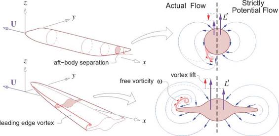
The conclusion that a rear-pointed body generates no lift assumes strictly potential flow. In reality, slender bodies will have some amount of flow separation if the rear taper is sufficiently rapid or if the local angle of attack is sufficiently large. Fuselages with large rear upsweep angles exhibit such rear separation, and slender delta wings at large angles of attack exhibit leading edge vortices. Figure 6.13 shows these flows, and compares them with their strictly-potential flow versions. Although the slender-body approximations and the 2D local far-field expansion (6.66) still remain reasonably valid with such separations, the strengths Л(х) and kz(x) will become significantly modified. In particular, the free vorticity which is antisymmetric in y will significantly modify the doublet strength kz, as can be seen from its definition (2.83). It will therefore modify the local and total lift, and also the moment. Specifically, the separation from the upswept rear body produces a downward bias in the local lift contribution, while the leading edge vortices on a delta wing significantly increase the upward lift, which is known as the vortex lift phenomenon. The effect is shown in Figure 6.14 for delta wings of two different aspect ratios.

Limits of slender-body theory

Figure 6.13: Viscous separation from an upswept rear fuselage, and leading edge vortices on a delta wing at high angle of attack. The free vorticity modifies the strictly-potential flow pattern, and also modifies the 2D strengths Л(х) and kz(x), and the associated aerodynamic loads.

Cambered body of revolution

A cambered body with circular cross sections is shown in Figure 6.11. Its surface geometry is defined by

r(x, e) = x x + [ R cos 9 ] y + [ R sin 9 + Z — ax ] z (6.70)

where Z(x) is the camber of the centerline, a is the overall body angle of attack, and R(x) is the radius of the local circular cross-section which is centered on z = z0(x) = Z(x) — ax.

The local normal vector is computed from (6.70) using the cross-product relation (6.61), with 9 = s/R.

Подпись: dR dZ і — R—: h a —— i?sm0 x + R cos 9 y + R sin 9 dx dx - (6.71)

Cambered body of revolution Подпись: У

z

In terms of the cross-sectional area A(x) = nR2, the far-field source and doublet strengths are

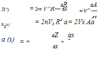
Подпись: Л^) dR dA = 2vr V^R— dx = v^ — dx Kz(x) = 2nVx R2 a = 2Vx Aa a (x) dZ qx = a — — h — dx (6.72)

(6.73)

(6.71) where a is the local angle of attack of the body centerline relative to the local body velocity U/(. The potential expression (6.66) with the strengths (6.72),(6.73), and the geometry given by (6.70) all together
exactly satisfy the 2D Laplace’s equation (6.62) and boundary conditions (6.63), (6.64). Therefore this far-field flow happens to be an exact solution of the transverse-flow equations for this geometry.

With the z-doublet strength known, the overall lift can be obtained by integration of the lift gradient (6.69).

L = j ^ da: = pV2 ёж = PVJ£ Add «№ (6.75)

This final result shows that within the assumptions of potential flow, the lift of a slender body of revolution depends only on its base area A(e) and the local angle of attack d(£) at the base location. Trefftz-plane analysis requires that any lifting body must generate trailing vorticity, and indeed the blunt base will shed the necessary vortex sheets as sketched in Figure 6.11. A related conclusion is that bodies which come to a sharp point at the rear cannot generate lift, since they cannot shed vorticity in the absence of flow separation.

The lift distribution dL/dx will also produce the following overall pitching moment (positive about the y axis) about the x = 0 reference point.

Mo = f —x-r~ ёж = pV2 f—x dx = — pV2 £ Ap) d{£) + pV2 f Ad ёж (6.76)

Jo dx о dx о

With zero base area and zero camber the lift is zero, and the pitching moment simplifies to

r f­M = pV2 a A dx = pV2 V a (6.77)

о

about any reference point x location, where V = /0A dx is the body’s volume. An important result is dM/da = pV2 V > 0. An angle of attack change да will therefore produce a pitching moment change AM of the same sign, which will tend to increase да even more. A body of revolution therefore exhibits an inherent pitch instability, which must be stabilized using fins as on a blimp or submarine, or gyroscopically via axial spin as on a finless projectile or a football thrown with a “spiral.”

Подпись: Kz (x) A'(x) Cambered body of revolution Подпись: (6.78) (6.79)

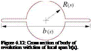
The results above have also been obtained by Ashley and Landahl [50] who used complex mapping to define the transverse flow. They also assumed a more general “finned” body of revolution with local span b(x) whose cross-section is shown in Figure 6.12. The local z-doublet for this case can be given in terms of an effective area A1,

Подпись: Figure 6.12: Cross section of body of revolution with fins of local span b(x).

while the local lift relation (6.69) remains the same. The total lift and moment is therefore given by ex­pressions (6.75) and (6.76) if the area A is replaced by the effective area A1 defined above. For the case b/2 = R where the fins have zero width, we have A1 = A, and the finned-body results reduce to the circular cross-section body results as expected.

2D unsteady flow interpretation

The sequence of solutions along x can be interpreted as a 2D unsteady flow p(t, y,z) if we make the Galilean transformation

Подпись: d Id dx VO dtx = Vo t

where the new observer is traveling along the x axis at the freestream speed V». The y(s; t), z(s; t) cross­sectional shape in the transverse plane and the resulting transverse flow then appear to change in time. In this unsteady interpretation the streamwise perturbation velocity transforms as px ^ pt/VO, which converts the steady 3D Bernoulli equation (6.65) into its 2D unsteady form which gives the same pressure.

P-Pco = ~P<Pt – + <fl)

In practice, when solving the 2D Laplace problem (6.62)-(6.64), the spatial sequence in x or the time sequence in t are computationally equivalent. And for computing the pressure, the 3D steady or the 2D un­steady Bernoulli equations are equivalent as well. Therefore, this transformation and unsteady interpretation does not provide any computational advantages, but it does give some additional insight into the problem.

6.6.3 Local 2D far-field

Подпись: where 2D unsteady flow interpretation Подпись: (6.66)

At intermediate distances which are large compared to the local body y, z dimension but small compared to the body length l, the perturbation potential must have a local 2D far-field form as given by (2.78).

The vortex term was omitted since there cannot be an overall circulation about this 3D body. The y doublet was omitted by the assumption of left/right symmetry about y = 0, and it can always be eliminated in any case by rotating the axes so that the z axis aligns with the doublet-vector axis. Also, for generality the singularities are placed at some location z = z0(x) rather than at z = 0.

Подпись: Л^) Подпись: v OO 1 dx Подпись: (6.67)

The source strength is related to the body’s cross-sectional area A(x) as derived in Section 2.12.

Подпись: pO - p Подпись: pVo Px 2D unsteady flow interpretation Подпись: (6.68)

The z-doublet is related to the lift via the the far-field lift integral (5.50). This requires the pressure, which is obtained from the Bernoulli equation (6.65),

Подпись: dL dx 2D unsteady flow interpretation Подпись: T r d Kz рУ^~г~ dx 2D unsteady flow interpretation Подпись: (6.69)

The quadratic terms in (6.65) have been omitted here, since they become negligible at a sufficiently large control volume. Following the procedure in Section C.4, integral (5.50) is now evaluated on a dx-long circular control volume of some radius r, whose arc length element is dl = r d9.

Using (6.69) to calculate the overall lift of the body still requires relating kz to the body geometry, which in general is case-dependent. A simple geometry is considered next as an example.

Slender Body Theory

Slender Body Theory is applicable to bodies such as slender fuselages and nacelles, and also to very slender delta wings with AR ^ 1. The key simplifying assumption, and the definition of “slender," is that the yz – plane cross sections of the body and the flow vary slowly in the streamwise x direction relative to the y, z directions. This implies that the streamwise component px of the perturbation velocity Vp is negligible compared to the transverse components py, pz.

Px < Py, Pz (6.59)

It’s useful to note the similarities with the Trefftz plane, introduced in Section 5.6.

6.6.1 Slender body geometry

The geometry of the body is specified by its surface position vector

Slender Body Theory

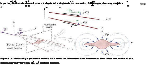
where s is some parameter, such as the arc length in the yz plane. This defines the y, z cross-section shape of the body at some x location, as shown in Figure 6.10. Since the vectors dr/ds and dr/dx are both tangent to the body surface, the unit normal vector can be determined via their cross product.

6.6.2 Slender body flow-field

The body is assumed to move at steady velocity U = — V» X and pitch rate О = q y, so the local apparent freestream is —Up = — (U + О x r) = V» X + qxz. Any angle of attack or sideslip is assumed to be included in the r geometry definition. The perturbation potential p(x, y,z) of the flow about the slender body is assumed to locally satisfy the two-dimensional crossflow Laplace’s equation

Pyy + Pzz = 0 (for y2 + z2 < f2 ) (6.62)

where f is the length of the body. Dropping the pxx term has been justified by the slender-flow assump­tion (6.59). The appropriate boundary conditions are flow tangency of the total velocity on the body surface, and asymptotically zero perturbation flow far away.

[ (V»+Px) X + Py y + (qx + Pz)z ] ■ n = 0

or Py ny + Pz Uz ^ — (V» Ux + qx Uz) (onbody) (6.63)

and P ^ 0 (for y2+z2 » f2) (6.64)

The Pxnx term has been dropped from the right side of (6.63) since it is negligible relative to the other terms.

Laplace’s equation (6.62) and boundary conditions (6.63),(6.64) define a 2D incompressible potential flow with a known nonzero normal velocity —(V» nx + qxnz) which is due to the pitch rate and also the incli­nation of the body surface relative to the freestream x direction. Such a flow is sketched in Figure 6.10 on bottom right. It can be computed for a given arbitrary cross-section using any standard 2D panel method, but with a different righthand side than usual. To compute the overall 3D flow, some sufficiently large number of individual 2D problems would actually have to be solved, one for each discrete x location.

Poo + pV*

-pVoo^Px – p (<Py + <pt)

Подпись: p Slender Body Theory Подпись: (6.65)
Подпись: p +

Once the potential p(x, y,z) is computed, the pressure is determined using the Bernoulli equation.

Even though the streamwise perturbation velocity px was neglected in the local 2D problem defined by Laplace’s equation (6.62) and boundary condition (6.63), it is required for the pressure calculation. The reason is that VOpx is not necessarily negligible compared to +P2 and hence must be retained here.

Trefftz-plane force calculation

As discussed in Section 6.4.4, the Trefftz-plane provides an alternative to the near-field result (6.6) for calculating the wind-axes forces. A suitable discrete formulation of the Trefftz-plane integrals which is applicable to the VL method here was already given in Section 5.8.2. To apply those results it is first necessary to define the piecewise-constant wake potential jump distribution д^>г for each h. v. “chord strip," shown in Figure 6.6, whose h. v.’s have their trailing legs superimposed in the Trefftz-plane.

Дфг = Г (6.51)

strip

The summation is only over the h. v.’s within that chord strip, indicated in Figure 6.6. The normalized version of expression (5.81) for the wake-normal velocity дф/диг and expressions (5.77), (5.78), (5.82) for the forces Y, L, D-і can then be used as written.

6.5.7 Stability and control derivative calculation

Trefftz-plane force calculation Подпись: CL(ao+Aa , во) — CL(ao , во) A a Подпись: Cn(ao , во+лв) — Cn(ao , во) Подпись: (6.52)

The VL method is well suited to rapid calculation of stability and control derivatives in the small-angle operating range a, P, p,q, r^ 1. The calculation can be performed by finite-differencing slightly perturbed flow solutions, e. g.

{sina cose 0 }

—cosa cos^J

d%f 90Zf

da 1г da 3* Л drj <T dU

£т^(г<) – ть

Подпись: d_ da Trefftz-plane force calculation Trefftz-plane force calculation Trefftz-plane force calculation Подпись: (6.53) (6.54) (6.55) (6.56) (6.57) (6.58)

A more economical alternative is to implicitly differentiate the overall force and moment summations with respect to each parameter via the chain rule, noting that rj as given by (6.41) and Vi as given by (6.42) have relatively simple dependencies on the parameters. For example, the a-derivatives of the following quantities can be evaluated in parallel with each quantity itself.

Note how each derivative calculation uses the derivatives calculated earlier. The final result (6.58) is the sought-after force stability derivatives with respect to a. The same procedure is used for the moment deriva­tive vector. The procedure is also repeated for all the remaining parameters e, p,q, r, St. The advantage of this direct differentiation method over the finite-difference approach (6.52) is that it is economical and effectively exact.

Near-field force and moment calculation

Подпись: Vi Подпись: = Vi Подпись: tXi I N [ Ux V г ) = Vj(Гі) - { Uy VZi J j = 1 Uz Гг = ^(ra + rb) Подпись: Q y Near-field force and moment calculation Подпись: (6.42) (6.43)

Once the Гг strengths are known, the normalized velocity relative to the midpoint гг of the i’th h. v. is calculated, as shown in Figure 6.9. This uses the same form as (6.32),

except the h. v. kernel functions Vj here are different than those in the flow-tangency condition (6.34), since the bound-leg midpoint locations гг are different from the control-point locations rC. In the Vj function in (6.42) it is also necessary to omit the bound leg’s contribution on itself, which is the first term in (6.33), since this is singular at гг.

Подпись: Fi Near-field force and moment calculation Near-field force and moment calculation Подпись: ti Гг Near-field force and moment calculation

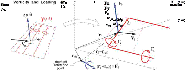
The normalized force Fг on each h. v. is computed by the integrated form of the local pressure loading relation (6.22).

The last step in (6.44) consists of lumping the vortex sheet on the element into the element h. v.’s bound leg vortex segment, 7 dS ~ ^Гг. The relevant quantities are shown in Figure 6.9.

Interestingly enough, the Kutta-Joukowsky force calculation form (6.45) gives exactly zero drag in the 2D case where there are no trailing h. v. legs. Therefore it implicitly accounts for the leading edge suction force, which then does not need to be added explicitly.

The total normalized force and moment on the whole configuration are obtained by summation of all the individual h. v. contributions. The moment is defined about a specified point rref.

N

F = £ F г

i= 1

(6.46)

N

M = ^(Гг – rref )x F г

i=1

(6.47)

The standard dimensionless force and moment coefficients in stability axes, shown in Figure 6.2, are ob­tained by rotating F and M using the T matrix given by (6.5). The reference span and chord bref, cref are

Near-field force and moment calculation

also used here to non-dimensionalize the moments.

If there is a nonzero sideslip, в = 0, then the physically correct expression for the induced drag coefficient is given by the wind-axis relation (6.8).

Подпись: (6.50)Cd = – F ■ U

Linear system setup and solution

Linear system setup and solution Подпись: U Подпись: и Подпись: Ux Uy Uz Подпись: cosa cose I с Г Ur I sine > , Cl = — = < йу > (6.38) sina cose L Uz

The subsequent numerical implementation of equations (6.37) will be done in terms of the following vari­ables normalized with VL, denoted by the overbar (). Note that U is then dimensionless, while Г and CC have units of length and 1/length, respectively.

Подпись: A. Подпись: Г, Linear system setup and solution Linear system setup and solution Подпись: (6.39)

The linearized flow tangency conditions (6.37) constitute an N x N linear system for the Г. normalized vortex strengths when the U, C, Si terms are placed on the righthand side.

Подпись: (6.40)A.j = Y?(ri) ‘ no.

The Aerodynamic Influence Coefficient matrix A., and the righthand side vectors in braces are functions of the vortex lattice geometry only, and hence are known a priori.

Multiplying (6.39) through by A-1 using LU-factorization and back-substitution gives the solution vector Г. as a sum of known 6+Ni independent vectors, whose coefficients (arbitrary at this point) are the operating

Linear system setup and solution Linear system setup and solution Подпись: (6.41)
Linear system setup and solution

parameters Ux, Uy … SN[. When these parameters are specified, Гi is determined by summing all 6 + N vectors.

Velocity field representation

Подпись: V(r) Velocity field representation Подпись: (U + О x r)

The overall velocity field relative to the VL configuration at any point r is given by relation (6.18), where the y(s, e) vortex-sheet strength is now lumped into the collection of h. v. filaments, with each filament having a constant strength Гi. The surface integral in (6.17) is therefore replaced with a collection of Biot-Savart line integrals, one for each h. v.

Evaluation of the Biot-Savart integral of the i’th h. v. has produced the V kernel function, given by the following expression. The a and b vectors are shown in Figure 6.7.

if axb /1 1 axx 1 bxx 1 1

47r|a||b|+a-b|a|^|b|y |a| — a • x |a| |b| — b • x |b| / ^ ^

Velocity field representation

The three terms in (6.33) correspond to the bound leg, the ra-point trailing leg, and the гь-point trailing leg, respectively. Note that Vi has units of 1 /length.

6.5.2 Flow tangency condition

Подпись: (U + flxrc) ■ n i(Si)Подпись: 0 (i = 1 ...N) (6.34)

Подпись: N Er Vj (r?) . j=1
Подпись: V(rc) ■ ni(Si)

The flow tangency condition (6.19) is imposed at the N control points by choosing r in (6.32) to be the control point r/ of each h. v. in turn, and setting the resulting normal velocity component to zero.

To avoid conflict with the control point index i, the summation index over the h. v.’s has been changed to j.

The normal vector ni depends on Si, which are control variables which define the deflections of some number of control surfaces. The control index l = 1, 2 …Ni is more practical for computation than the earlier Sa, Se … notation introduced in Section 6.3.2.

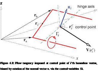
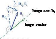
The deflections are modeled by rotating each ni on that control surface about a specified hinge axis. In keeping with the small-angle approximations used throughout lifting surface theory and the VL method in particular, each normal vector’s dependence on Si is linearized. Referring to Figure 6.8 we have

Ni

Подпись: ni№) dn i– noi + E nii Si (6.35)

1=1

= gi hii xnoi (6.36) where hi is the hinge-axis unit vector about which n rotates in response to the Si control deflection, and gi is the “control gain,” included so that the Si control variable doesn’t have to be the actual local deflection angle in radians. To linearize the control influence we will assume that —U/x — V/, x which is equivalent to
а, в ^ 1, and that the normal-vector control deflections щ. Si are small compared to the undeflected normal vector no.. Thus the flow-tangency equations (6.34) are approximated by

Ni

у,(rf) – (U + Oxr£) ■ no. + £ VL X ■ ni. Si = 0 (i = 1. ..N) (6.37)

j=i 1=1

Подпись: z Figure 6.8: Flow tangency imposed at control point of i’th horseshoe vortex, biased by rotation of the normal vector n. via the control variables Si. Подпись: У Velocity field representation

where all products of two small quantities have been dropped.

Trefftz-plane loads

An alternative to the above near-field force calculation is to use the far-field or Trefftz-plane approach. In general, this is a more reliable approach especially for the Di component, since it avoids the usual pressure- drag cancellation errors discussed in Chapter 5, these being especially problematic with the simple leading Vortex Lattice Method

The Vortex Lattice (VL) method is a numerical solution implementation of the general 3D lifting surface problem described above. It is also the simplest general 3D potential flow calculation method. It is com­monly used in initial aircraft configuration development, where its simplicity and speed allow a large number of configurations to be examined. It is also used for initial structural load estimation, and to provide the trim state values and stability and control derivatives for the linearized force and moment equations (6.12), (6.13).

6.5.1 Vortex lattice discretization

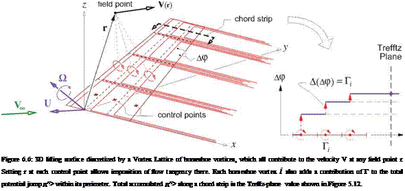
Подпись: Figure 6.6: 3D lifting surface discretized by a Vortex Lattice of horseshoe vortices, which all contribute to the velocity V at any field point r. Setting r at each control point allows imposition of flow tangency there. Each horseshoe vortex i also adds a contribution of Г to the total potential jump д^> within its perimeter. Total accumulated д^> along a chord strip is the Trefftz-plane value shown in Figure 5.12.

The VL method discretizes the vortex-sheet strength distribution on each lifting surface and its wake by lumping it into a collection of horseshoe vortices, as shown in Figure 6.6. Each horseshoe vortex (h. v.) consists of three straight legs, or segments: a bound leg which lies on the surface, and two trailing legs extending from the bound leg’s endpoints to downstream infinity and parallel to the x axis. All three legs of the i’th h. v. have the same constant circulation strength Г.

In a discrete sense, this configuration of vortices satisfies the zero-divergence requirement on the vortex sheet strength y(s, e) which is discussed in Section 2.4, since any circuit drawn on the surface will have a filament with a fixed circulation both entering and leaving it. Note also that each h. v. adds zero net circulation in the Trefftz plane, where its two trailing legs have equal and opposite circulations.

An equivalent interpretation of the h. v. configuration is a piecewise-constant potential jump or normal – doublet distribution. Each h. v. contributes Д(д^>) = Г to the total potential jump д^> within its perimeter. The total circulation of all the h. v.’s in a chord strip then gives the д^> in the Trefftz plane, as shown in Figure 6.6. This д^> is also shown in Figure 5.12, where it’s used to construct the Trefftz-plane velocity and evaluate the Trefftz-plane forces.

Near-field loads

Подпись: AP = Pi - Pu Подпись: p A(V-V) = pVa- AV Подпись: (6.21)

Once the surface vortex sheet strength 7(s,£) distribution is known from the solution of the lifting-surface problem as described above, the resulting pressure jump or equivalently the loading can be determined using the Bernoulli equation as follows.

aV = Vu – Vi = 7 x П

V0 = ^(V« + V/) = (V7)0 – (U + Oxr)

The ()u and ()i subscripts denote the upper and lower sides of the surface, as also used in Section 5.4 for a wake. Here (VY)a is the velocity of the entire vortex sheet configuration, averaged between two field points on the two sides of the sheet. An equivalent version of the loading expression (6.21) is

Ap n = p Va x Y (6.22)

which in effect is a local Kutta-Joukowsky relation.

Near-field loads

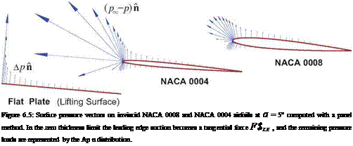
The lifting surface approximation largely neglects the details of the flow in the leading edge region, which consequently requires a special treatment in the force calculations. Figure 6.5 shows the actual (pTO-p) n surface load vectors on 2D inviscid airfoils of different thicknesses. The strongly negative pressure distribu­tion acting on the small leading radius is known as leading edge suction, and is the mechanism by which the pressure drag of the aft-pointing pressure forces over the rest of the airfoil are canceled. In 2D the cancella­tion is theoretically perfect, while in 3D the cancellation is partial but still very significant. This problem of properly capturing pressure drag was raised previously in the near-field force analysis in Section 5.1.2.

The leading edge suction force can be determined by applying the integral momentum theorem to a control volume enclosing the leading edge point, and assuming that the local vortex sheet strength varies as

Подпись: C

Near-field loads Near-field loads

Y(x)

where C is now determined from the actual sheet strength y(«4) of the solution, and t is the unit tangential vector pointing ahead of the leading edge, and normal to both n and the leading edge line.

The overall force and moment on the configuration from the normal forces are finally obtained by integration of the pressure loading distribution and also the leading edge suction forces over all the surfaces.

F = Ap n ds d£ + F’Sle ds (6.24)

surfaces Surface JL. E.

M = Ap rx n ds df + / rx FSlb ds (6.25)

surfaces surface L. E.

The integration over the wakes is not performed. The rationale is that a real wake must have Ap = 0 anyway, even if this isn’t quite true in the simplified lifting-surface model in which the wake 7 is assumed to be aligned with X. To get a truly force-free wake in the model would require aligning the wake geometry and its strength 7 with the local Va direction. This would make the lifting surface problem nonlinear, since the geometry of the vortex sheets would then depend on the flow solution itself. All these complications are sidestepped by assuming the fixed X wake direction and simply ignoring the resulting implied wake loads.