The induced drag definition (5.31) is awkward or impractical to evaluate as written because of the infinite double integral. It can be simplified considerably by using the identity
V/ – V/ = V-(/ V/) — / V2/ (5.42)
which is valid for any differentiable function /. Choosing / = p, which satisfies the continuity requirement V2p = 0, simplifies the identity to the following form.
Vp ■ Vp = V-(p Vp) (5.43)
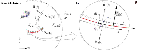
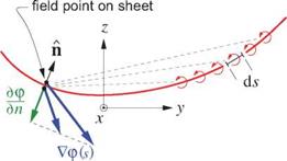
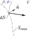
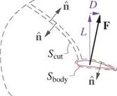
Referring to Figure 5.10, the induced drag integral (5.31) then becomes
A = JJ ^ pc* Ур • Ур dS = JJ ^ Pc* V • (p Vp) dS
= J ^ pVp ■ n dl (5.44)
where the last step (5.44) was obtained via the Gauss Theorem. This integral is over the outer contour with arc length l, and its unit normal vector n points out of the domain.
The outer contour must have p continuous inside, otherwise Gauss’s Theorem or identity (5.43) would not be valid. This requires placing the vortex sheet (and its Ap jump) topologically outside the contour, as shown in
Figure 5.10. For the three contour pieces Swake, Scut, Souter, the contribution of Souter to integral (5.44) will vanish when it’s taken out to infinity, and the contribution of piece Scut is always zero by antisymmetry of its two n vectors. For the only remaining piece Swake wrapped around the wake vortex sheet, the following relations hold for the two opposing points 1,2:
П i(i) = —П 2(1) = П (s) (5.45)
dl = ds (5.46)
The Swake surface integral around the wake can now be replaced by an integral along the wake, and further simplified using the potential jump definition Ap = p2 — pi.
p Vp ■ П dl
wake
[ [ pi Vpi ■ n 1 + p2 Vp2 ■ П2 ] ds [ pi Vpi ■ n — P2 Vp2 ■ n ] ds
The profile drag expression (5.34) or (5.36) based on the momentum defect, together with the induced drag expression (5.47) based on the crossflow kinetic energy, provide a relatively simple and quite accurate means of calculating or estimating the overall drag of a general 3D configuration.
The required input for the profile drag expression is the spanwise momentum defect distribution P(s). The input for the induced drag expression is the wake sheet potential jump distribution Ap(s). Both of these can be obtained with a suitable combination of inviscid and boundary layer calculation methods, preferably coupled via one of the displacement-effect models. The overall far-field drag is relatively accurate, since it does not suffer from pressure drag cancellation errors which make near-field pressure drag calculation unreliable.
The first righthand side term in the identity (5.57) vanished inside the contour integrals via Gauss’s Theorem and the div(curl) = 0 identity.
£ [Vx(flv)| ■ n dS = V-[Vx(av)]dV = 0 dV = 0
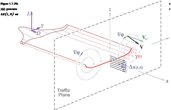
For the final step in simplifying the sideforce and lift expressions (5.58), (5.59) we note that their integrands are nonzero only on the Trefftz plane where the trailing vorticity и exits the control volume. Here we have П = X, so that и ■ П = wx where the scalar шх is the streamwise vorticity component along x. As in the drag derivations, we now also make the assumption that the viscous wake is thin, so that the area element can be recast using the sheet’s coordinates, dS = dn ds, which permits lumping of the vorticity шх into the equivalent vortex sheet strength 7 = J шх dn.
I Smax
 Y = P^C —zwx dn ds = pTOL -27 ds
JJtp J 0
l Smax
L = PlL ушх dn ds = pTOL VY ds
TP 0
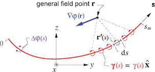
Next, using relation (5.37), the vortex sheet strength is replaced by the potential-jump derivative, and the resulting expressions are integrated by parts.
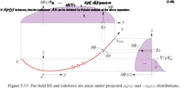
Since the potential jump is zero at each end of the sheet, the first term in (5.62) and (5.63) disappears. The final expressions for the far-field sideforce and lift are then simple integrals of the potential jump or jumps over the — z and у projections of the vortex sheet, as shown in Figure 5.11.
For this reason, the wake potential jump Ap is frequently called “the loading," since the quantity pL Vl Ap is in effect the load/span acting on the body which is shedding the wake, and acts normal to the wake.


![]() ri — 1/2 — Api — 1 Api
ri — 1/2 — Api — 1 Api


