Category Flight Vehicle Aerodynamics

Viscous dissipation relations

In Section 4.5.4, viscous dissipation was shown to be ultimately responsible for total profile drag, including the pressure drag component. Since dissipation is therefore a key quantity to be minimized, it’s useful to examine how the dissipation coefficient cD depends on the other boundary layer parameters. For self-similar laminar flow, this dependence is given by Table 4.1. For self-similar turbulent flow, it can be obtained from the kinetic energy shape parameter equation (4.98) together with the G-beta locus (4.58) as follows.

dff*

ds

Подпись: ~ 0 Подпись: (equilibrium flow) (4.99)

Since turbulent equilibrium flows have a streamwise-constant G, they must have a very nearly constant H and hence also a constant H* if we neglect the slight streamwise variation of the turbulent Jcf /2 factor in the G definition (4.56).

я* Гс/ / H-1 1 ҐН-13

~2 ~2~ BH ) + ~Ш H )

Подпись: CD (H,Bee) Подпись: (equilibrium flow) (4.100)

We can now obtain an expression for equilibrium-flow cD from (4.98) by dropping the dH*/ds term and eliminating в/ие due/ds using the G-beta locus (4.94). The H** term is also dropped since this is typically small, and is exactly zero in incompressible flow.
Viscous dissipation relations

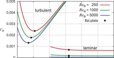
Aside from additional minor non-equilibrium corrections, expression (4.100) is in fact used in two-equation methods as a closure function for cD in the ODE (4.98) to enable its integration. It is shown in Figure 4.25 for several momentum thickness Reynolds numbers. Also overlaid is the laminar cD(H, Bne) function for the laminar Falkner-Skan flows, tabulated in Table 4.1. The turbulent cD is seen to have a fairly weak dependence on Req, while the laminar cD ~ 1 /Bee dependence is much stronger.

1 1.5 2 2.5 3 3.5 4

H

Figure 4.25: Dissipation coefficient for self-similar flows. Laminar values are listed in Table 4.1. Turbulent values are given by equation (4.100). Weak pressure gradients which displace H slightly from the flat plate value have little effect on cD.

For any given local Bee, the minimum dissipation occurs very close to the zero pressure gradient (flat-plate) H value, so that the dissipation is relatively insensitive to small changes in H, i. e. to weak favorable or adverse pressure gradients. The laminar cD is also very nearly independent of pressure gradient.

The weak dependence of cD on pressure gradients (assuming fixed transition locations) indicates that the dissipation V{s) = peJ cv is primarily determined by the cube of the edge velocity And since the inte­grated D(s) distribution gives the profile drag via expression (4.49), airfoils which have strong “overspeeds” or regions of high velocity are expected to have large integrated dissipation and high drag. Conversely, low drag is likely to be achieved by airfoils which have more uniform velocity distributions.

Note that since expression (4.49) captures the sum of friction and pressure drags, this argument applies to both the friction and pressure drag components. Attempting to reduce the pressure drag “directly,” for example by reducing pressures on front-facing surfaces and increasing pressures on aft-facing surfaces, is bound to be futile if viscous dissipation is not reduced in the process.

2cd

IT*

Подпись: Лг Подпись: 9 d ue ue ds Подпись: min Viscous dissipation relations Подпись: ~ -0.65 cD Подпись: (4.101)

Another important role of the dissipation coefficient is that it controls the maximum tolerable adverse pres­sure gradient which a boundary layer can sustain with a constant margin from separation, or equivalently with a nearly constant H and H*. In this situation the shape parameter equation (4.98) with dH*/ds = 0 can be viewed as an equation for the most negative tolerable velocity gradient.

The second approximate value in (4.101) is valid for turbulent flow in very strong adverse pressure gradients near separation where H~3, H* ~ 1.5, and Cf is relatively negligible.

One implication of (4.101) is that the adverse pressure gradient capability of the boundary layer can be increased by increasing its dissipation, preferably away from the surface so that the offsetting Cf term in (4.101) is not increased as much. One common technique is by the use of vortex generators [27], which
increase dissipation by introducing streamwise vortices into the boundary layer at some distance from the wall.

Two-equation methods

Thwaites’s method and White’s equilibrium method are examples of one-equation integral methods, mean­ing that they integrate one differential equation to obtain the solution. One of their main drawbacks is that they cannot correctly represent the behavior of a separated boundary layer. For Thwaites’s method this can be seen by examining the H and A column values in Table 4.1. For adverse pressure gradients (A < 0) this
true H(A) function is actually two-valued, with one H < 4 value which is the attached solution, and another H > 4 value which is the separated solution. Even if the curve-fit H(A) expression (4.85) were somehow modified to have this two-value form, it would be impossible to use in the H evaluation step (4.90), since there’s no way to know whether to choose the attached or the separated H value for any given negative A value.

This problem is eliminated by the so-called two-equation integral methods, such as those of LeBalleur [23], Whitfield et al [24], and Drela et al [6]. These methods integrate both the von Karman equation (4.28) for 9(s), and also the kinetic energy equation (4.35) for в*, or equivalently for H* = 0*/0. The latter is actually obtained more conveniently from the combination [equation (4.35) ]/в* — [ equation (4.28) ]/в which produces the kinetic energy shape parameter equation.

Подпись: (4.98)1 dH* = 2cv cf ґ 2H** в due

H* ds H* 2 H* ) ue ds

Two equation methods assume that H and H* are uniquely related via a H*(H) correlation function, so that equation (4.98) above is in effect an ODE for H(s). For laminar flow, the H*(H) function is implied by Table 4.1. For turbulent flow, a H*(H, Bee) function is obtained from the self-similar turbulent profiles shown in Figure 4.14, but actually differs very little from the laminar version. Since H is calculated directly in the two-equation methods, there is no ambiguity as to whether the flow is attached or separated at any given location. In these methods A or Л is not needed and is not used explicitly.

Another type of two-equation method is developed by Head [25] and Green et al [26], and is based on the entrainment equation, which is an integral form of the mass equation. The behavior of entrainment-based methods is similar to those of the kinetic energy-based methods, and the details are not important here.

Besides enabling the representation of a separated boundary layer, two-equation methods are considerably more accurate than the one-equation methods, especially for turbulent flow. Since their derivation makes the same basic correlation assumptions as the one-equation methods, i. e. the Falkner-Skan solutions for laminar flow and the equilibrium profiles and G-beta locus for turbulent flow, presenting them in detail here would add little besides complexity. The reader is referred to references for the derivation details.

White’s equilibrium method

The Thwaites method’s functions Fq(a), T(a), and H(A) are valid only for laminar flow. To integrate the von Karman momentum equation (4.28) for a turbulent boundary layer, it is necessary to provide turbulent closure relations for Cf and H, ultimately in terms of the primary unknown в and the inputs v and ue. Such an approach is described by White [22], mainly for illustrative purposes. It is summarized below.

Подпись: Cf (H,Ree) Подпись: 0.3 е_1'ззя (og10Bee)h74+0-31H Подпись: (4.93)

A suitable turbulent skin-friction relation is the Coles formula, which is a fit to equilibrium flow data.

White’s equilibrium method Подпись: — - BH Л 2 в due A Cf в ue ds ReQ 2 H Подпись: (4.94) (4.95)

A suitable turbulent shape parameter relation is the G-beta locus (4.58), after replacement of G and в by their definitions (4.56), (4.57). Squaring both sides and further multiplying through by Cf /2A2 gives the more convenient form

where Л is a new pressure-gradient parameter. This is a scaled version of Thwaites’s A, and is more relevant for turbulent flows.

Подпись: Л, ReQ Подпись: eq .(4 .93) eq.(4.94) Подпись: Cf (Л,Вгв) H (Л,Вев) Подпись: (4.96)

Equations (4.93) and (4.94) are two constraints between the four parameters H, Cf, Л, Re#. If Л and Re# are specified, these equations can be numerically solved (e. g. by Newton iteration) for the corresponding H and Cf values. Hence, we in effect have

which are the direct replacements of Thwaites’s T(a) and H(a) closure functions.

We can now insert the Cf and H functions (4.96) into the von Karman equation (4.28), putting it into the following functional form.

^ = ^ef(A, Bee) – (й(А,&в) + 2^ Л = f(e, ue, v) (4.97)

If v and ue(s) are provided, then this can be numerically integrated for the в(«) distribution, usually starting from the transition location str. The initial value e(str) is also required, and typically would be obtained from the last laminar в value at str.

In contrast to the laminar boundary layer Reynolds number independence discussed earlier, turbulent bound­ary layer evolution is affected by Reynolds number. This can be seen from the explicit appearance of the Reynolds number in the H(Л, Взв) function (4.96). In general, increasing Re# tends to decrease H slightly, giving slightly greater resistance to adverse pressure gradients. Consequently, increasing the overall Reynolds number of a turbulent flow tends to delay separation and increase maximum lift.

Reynolds number independence

It is interesting to note that the boundary evolution predicted by the Thwaites formula (4.87) with zero initial values at s0 obeys the simple scalings

9(s) ~ [v ~ 1JyjBe, Cy(s) ~ yjv ~ 1 jy/Bk (4.92)

Reynolds number independence

with A(s) and H(s) completely unaffected by the viscosity, or more generally by the Reynolds number. The conclusion is that aside from the simple fBe- scalings, boundary layer evolution and in particular the separation location is independent of Reynolds number, as sketched in Figure 4.24. Only the shape (but not the magnitude) of the input ue(s) distribution matters. This conclusion also holds for effectively exact finite-difference solution methods.

Figure 4.24: For a prescribed ue(s), the resulting shape parameter H(s) distribution of a laminar boundary layer is independent of Reynolds number. The skin friction and momentum thickness distributions arc also unaffected except for simple Cf(s), 9{s) ~ 1 / [Вє – scalings.

However, the assumption that ue(s) is fixed and independent of Reynolds number is not exactly correct for a fixed body geometry. As examined in Chapter 3, the overall potential flow-field and hence ue(s) are affected by the viscous displacement mechanism. The resulting changes to ue(s) themselves scale as 5* ~ 1 / [Вё – and hence are very small, but only if the flow is attached. So in actual applications the Reynolds number independence of laminar flow is only approximately correct, and only in the absence of flow separation.

Integral Boundary Layer Solution

4.11.1 Thwaites method Assumptions and formulation

Integral Boundary Layer Solution

The Thwaites method [21], [11], [12] solves the classical low-speed laminar boundary layer problem by as­suming specific functional forms for Cf, H, and the entire righthand side of the von Karman equation (4.28). This is first manipulated by multiplying 2Req x [equation (4.28)], where

Подпись: T Integral Boundary Layer Solution Подпись: d U d{n/9) Подпись: 62ue s due vs ue ds Integral Boundary Layer Solution Подпись: d 2U d{n/9)2 Подпись: (4.83)

where T is a normalized wall shear, and A is a normalized edge velocity gradient or equivalently a normal­ized pressure gradient. For the power-law flow case ue = Csa these are also products of Falkner-Skan solution parameters, and also of the normalized velocity profile derivatives at the wall.

Their numerical values are listed in Table 4.1. Also listed is the entire righthand side parameter combination Fq in the manipulated von Karman equation (4.81).

For power-law flows, all the Falkner-Skan parameters (columns of Table 4.1) are functions of the expo­nent a, or more generally functions of each other. The key assumption of Thwaites’s method is that the A), Ffl(A) relations arc valid for any boundary layer flow, not just a power-law flow. In effect this assumes that the boundary layer profile U{iy, s) at each s location has the same shape as one of the Falkner- Skan profiles. That is, if A is known at a location s in a general flow, then H, T, Fq at that location are also immediately known from the corresponding row in Table 4.1.

Explicit integration

Rather than use the Falkner-Skan solutions in Table 4.1, Thwaites examined a number of other theoretical flows to quantify these functions. For Fe he chose

Fe(A) = 0.45 – 6A (4.84)

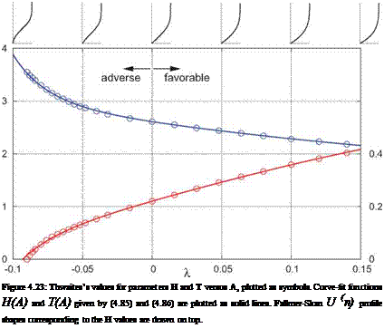
which doesn’t quite match the values in Table 4.1, but it is close. His H and T were provided in tabulated form. They are shown in Figure 4.23, and are closely approximated by the following convenient curve fits.

Подпись:Я, л, = 2.61-4ЛА + 14А* + р24^_

Подпись: Figure 4.23: Thwaites’s values for parameters H and T versus A, plotted as symbols. Curve-fit functions H(A) and T(A) given by (4.85) and (4.86) are plotted as solid lines. Falkner-Skan U (n) profile shapes corresponding to the H values are drawn on top.

T, a, = Um + l-m-SA’-jOTP

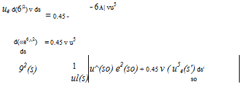
Strictly speaking, equation (4.81) could be numerically integrated using only the T(A) and H(A) functions inserted in its righthand side. However, the fact that their combination Fe(A) is very nearly linear allows a simpler explicit solution. When the approximate Fe(A) given by (4.84) is inserted for the entire righthand side of equation (4.81), and the entire equation is then multiplied by vu5, its lefthand side becomes a perfect differential which can then be explicitly integrated.

Подпись: ue d(6|2) v ds = 0.45 - - 6A| vu5 d(«e6^2) ds = 0.45 v u5 92(s) 1 ul(s) u^(so) e2(so) + 0.45 v ( u5e(s') ds' so (4.87)

Integral Boundary Layer Solution Integral Boundary Layer Solution Подпись: (4.88) (4.89) (4.90) (4.91)

If ue(s) and v are provided, the corresponding 9(s) can be immediately obtained by evaluation of the integral in (4.87), numerically if necessary. This 9(s) is then used in the closure relations to obtain the remaining quantities of interest.

In general, the integral in (4.87) is evaluated from some initial location s0 where 9(s0) must be specified. But if this s0 is the sharp leading edge of a Blasius flow, then 9(so) = 0. Alternatively, if s0 is at a blunt leading edge stagnation point, then ue(s0) = 0, in which case 9(s0) in (4.87) is immaterial. Hence, in both of these typical situations no initial data is required.

Integral solution methods

Instead of computing the detailed u, v, т(s, n) fields, integral methods determine only the integral thicknesses and key shear quantities, namely 5*, 6, Cf, cD(s), etc. This relatively small number of unknowns makes the integral methods very economical, but a drawback is that their solutions must always be approximate, in
that they cannot produce theoretically exact solutions of the laminar boundary layer equations (4.21). For turbulent flows this is not really an issue, since even nominally “exact” solutions of equations (4.21) still require turbulence models for jt which are inherently approximate. In practice, the simpler and much more economical integral methods are sufficiently accurate for a large majority of aerodynamic flow prediction applications, for both laminar and turbulent flows.

To compute the integral thicknesses 5*, 6, 6*(s), integral methods solve either the von Karman equation (4.28) or the kinetic energy equation (4.35), or both as in some advanced methods. In effect, they seek to evaluate the integrals in (4.36) and/or (4.38) in some manner. Here we will focus on solving only the von Karman equation (4.28). This equation is not integrable as written, because it contains the terms Cf and H which are additional unknowns, and therefore require two additional closure relations or functions to relate them to the primary variables 6,ue, v. How these additional unknowns are determined is primarily what distinguishes the many different integral calculation methods which have been developed to date.

2D Boundary Layer Solution Methods – Overview

4.10.1 Classical boundary layer problem

The classical incompressible 2D wall boundary layer problem has the following inputs and outputs.

Inputs: Outputs:

v or Reref viscosity or Reynolds number u(s, n),v(s, n) velocity field

ue(s) edge velocity distribution 5*(s),6(s) … thicknesses, from u(s, n)

u0(n),v0(n) initial velocities at s0 H(s),Cf (s) shape parameter, skin friction

The inputs are quantities which appear in the boundary layer equations (4.21) and boundary conditions (4.22). The outputs are the unknowns in these equations, or functions of these unknowns.

The initial velocities u0,v0 at the first location s0 (shown in Figure 4.22) are not needed if this is a leading edge or stagnation point, which is the most common situation. In this case they can be taken from one of the self-similar solutions treated earlier.

4.10.2 Finite-difference solution methods

2D Boundary Layer Solution Methods - Overview

The most general solution approach is the grid-based finite-difference method, sketched in Figure 4.22. The solution procedure solves for all the u, v unknowns at one s station at a time, starting at the first s0 station. This solution procedure is known as space marching. For details, see Cebeci and Smith [19], Cebeci and Bradshaw [20].

For the general boundary layer problem, the space-marching finite-difference solution procedure is accurate and effective, but requires considerable computational effort. For acceptable accuracy for laminar flows, it requires at least 20 or more grid nodes across the layer at each surface point, with the three u, v, т unknowns per grid node. Turbulent flows may require 80 or more grid nodes per surface point. A typical ue(s) dis­tribution, over an airfoil surface say, might require over 100 surface points, resulting in many thousands of unknowns for the entire 2D boundary layer. When the boundary layer is to be solved simultaneously with the potential flow, as will be described in Section 4.12.2, this large total number of unknowns is prohibitive. Another drawback of the finite-difference method is that it is purely numerical, and gives no direct insight into boundary layer behavior. An alternative approach is taken by the integral methods, described next.

Crossflow gradient effects

Although the infinite swept wing has a 3D boundary layer with crossflow, one simple explanation why the crossflow is immaterial to the boundary layer development is that there is no crossflow gradient, in the spanwise z direction in that case. In contrast, in more general 3D boundary layers with nonzero crossflow gradients, such as the one sketched in Figure 4.21, the presence of the crossflow will certainly have an effect.

Подпись: Growth of 2D boundary layer without crossflow convergence Figure 4.21: Crossflow convergence increases boundary layer growth compared to a 2D boundary layer with the same streamwise profile. Crossflow divergence would have the opposite effect.

In general, any lateral gradient in the crossflow will cause lateral convergence/divergence effects as in the axisymmetric case, except here the convergence or divergence occurs only near the wall rather than over the whole boundary layer thickness. However, the overall effect is the same, with the boundary layer growth being increased or decreased relative to the 2D case without crossflow. Figure 4.21 shows a case with crossflow convergence, causing an additional boundary layer thickening. Crossflow divergence would have the opposite effect.

. Infinite swept wing Swept-wing potential flow

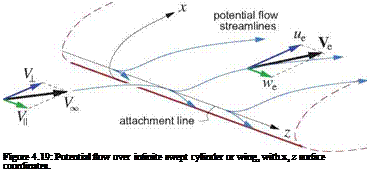
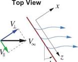
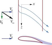
An infinite swept cylindrical body, such as a wing for example, is shown in Figure 4.19. The perpendicular and parallel freestream velocity components are

V± = VTO cos Л V = VTO si^

Подпись: Figure 4.19: Potential flow over infinite swept cylinder or wing, with x, z surface coordinates.
. Infinite swept wing Swept-wing potential flow

where Л is the sweep angle. The x, z surface coordinates are chosen such that z runs spanwise, with x being the usual 2D-like chordwise coordinate.

Since there is no special z location on the wing, we must have

^>=0

. Infinite swept wing Swept-wing potential flow . Infinite swept wing Swept-wing potential flow

for all flow quantities. In the potential flow, the z-momentum equation which governs we then simplifies to

PeO = Pc* ( y~

. Infinite swept wing Swept-wing potential flow . Infinite swept wing Swept-wing potential flow Подпись: (4.75) (4.76)

The local pressure is given by the isentropic relation (1.112), or by the Bernoulli equation (1.112) for the case of low speed flow.

In either case, the spanwise velocity we has no influence on the pressure, and hence no influence on the lift. It is therefore appropriate and useful to define “perpendicular” pressure and lift coefficients referenced to the perpendicular dynamic pressure,

Подпись: Cpx = c£± =Pe-Pco pooV’l

where ACp± is the pressure coefficient difference between the lower and upper surface of the airfoil, and cL is the perpendicular chord. These quantities correspond to those of a 2D flow in which the spanwise velocity V is absent. So for example, CP± (x ; ) and в£± («x ) on a high aspect ratio swept wing can be obtained from

2D calculations or 2D experimental data, with

fyert

a± = arcsm ——

Vl

being the angle of attack seen in the perpendicular plane, and VVert is net vertical freestream velocity reduced by the local 3D induced downwash velocity.

Swept-wing boundary layer flow

Подпись: du dv dx dy du du UTT~ + v— dx dy dw dw u~, h v— dx dy . Infinite swept wing Swept-wing potential flow Подпись: (4.77) (4.78) (4.79)

With the d()/dz = 0 condition, the 3D boundary layer equations for low speed flow, with the kinematic eddy viscosity vt = pt/p invoked, simplify as follows.

Evidently (4.77) and (4.78) are the 2D boundary layer equations in x, y, decoupled from the z-momentum equation (4.79) and the spanwise w velocity. As pointed out in the previous section, ue(x) and the pressure are the same as in a 2D flow with we absent. Hence, the chordwise velocities u, v governed by (4.77),(4.78) are also the same as in 2D flow, and are unaffected by the spanwise flow component.

Because neither the local potential flow nor the boundary layer flow are affected by the V spanwise veloc­ity component, the overall conclusion is that the relevant airfoil shape which determines the aerodynamic characteristics of a swept high aspect ratio wing is perpendicular to the wing, not parallel to the freestream direction. In particular, adding a spanwise freestream velocity component to a given wing does not affect its surface pressures and lift, and also does not affect its boundary layer its separation resistance or chordwise separation location for the same perpendicular-plane angle of attack. This is shown in Figure 4.20.

. Infinite swept wing Swept-wing potential flow

Figure 4.20: Adding a spanwise freestream velocity component V does not affect a wing’s lift, or the characteristics of a laminar boundary layer projected onto the perpendicular plane. A turbulent boundary layer will change somewhat from the larger Reynolds number’s effect on the turbulence.

The independence of the chordwise u(x, y) velocity from the spanwise w(x, y) velocity is strictly valid only for laminar flow. For turbulent flow, the spanwise velocity will increase the effective Reynolds number of the turbulence, and hence will have some effect on vt, so the decoupling isn’t perfect. Nevertheless, since Reynolds number effects on turbulence are weak, the conclusions are very nearly correct also for turbulent flow. McLean [18] discusses the effects of wing sweep on boundary layers in much more detail.

3D Boundary Layers

Three dimensional boundary layer flows can be quite complex, and a complete treatment of 3D boundary layer theory is far out of scope here. Only a general overview of the key new effects will be given here. See McLean [18] for a much more comprehensive discussion.

4.9.1 Streamwise and crossflow profiles

A 3D boundary layer features non-planar velocity profiles V(n), such as the one shown in Figure 4.18. Traditional notation uses s,s2,n as the local cartesian coordinates (instead of s,£,n), with si parallel to the edge velocity vector Ve, and s2 perpendicular to it. Within the boundary layer we then have

V(n) — ui si + U2 S2 (4.72)

where u1(n) is the streamwise profile, and u2(n) is the crossflow profile which appears only in 3D boundary layers. The presence of crossflow means that the wall shear stress vector Tw is in general not parallel to the local edge velocity. The lines parallel to Tw are called wall streamlines, which differ from the usual potential-flow streamlines which are parallel to Ve.

Crossflow is typically generated by a transverse pressure gradient dp/ds2 which is felt by the fluid over the entire boundary layer thickness. The slower-moving fluid within the boundary layer curves in response more strongly than does the outer potential flow, and thus forms the crossflow profile some distance downstream, as shown in Figure 4.18 on the right. This is essentially the same mechanism as the one shown in Figure 4.6, but here it occurs in the transverse direction.