Category Flight Vehicle Aerodynamics

3D far-field effect of drag

A 3D body with profile drag will have a viscous wake with some velocity defect Auwake(y, z) = u — VL, shown in Figure 2.18. Following the 2D airfoil analysis of Appendix C, the far-field source strength is the integrated volume flow rate of the wake velocity defect, and the profile drag is the associated integrated momentum defect.

£ = — Auwake dy dz (2.108)

Dp = JJ(VL+Auwake)(—Auwake) dy dz (2.109)

The drag derivation will also be given later in Section 5.6.

3D far-field effect of dragIn the far wake we also have Auwake ^ 0, so that the two relations above can be combined to give the far-held source strength in terms of the profile drag Dp of the body, or equivalently in terms of its profile drag coefficient Cdp based on some reference area Sref.

£ = = lv^SreiCDp (2.110)

3D far-field effect of drag

pVO 2 p

2.12.1 3D far-field effect of volume

Подпись: A(x ) Подпись: x 3D far-field effect of drag

The inviscid flow about a slender body of revolution, such as an airplane fuselage, can be accurately rep­resented by a variable-strength source filament placed along the body centerline, superimposed with a freestream. This model is shown in Figure 2.19.

x

Figure 2.19: Flow about slender body represented by a source filament of variable strength Л(х).

Подпись: Л dx = V■ n dS = Vo(A+dA) Л(х) = dA V — o dx Подпись: Vo A = VO dA (2.111)

Following the 2D airfoil thickness analysis, the source filament strength Л(х) can be determined by mass conservation applied to the local control volume which has the body’s cross sectional area A(x) and is dx thick in the axial direction. The flow is required to be tangent to the outside perimeter surface of the control volume, so the net outflow from the source filament inside is equal to the volume flow difference between the front and rear faces of area A and A + dA, as given by (2.39). This gives the required source filament strength.

3D far-field effect of drag Подпись: (2.112)

The far-field x-doublet for this source filament is then determined from the KX definition (2.105).

The last integral above can be integrated by parts as in the 2D case, giving a rather simple expression for KX in terms of the body volume V = XTE A dx.

XLE

Подпись: (2.113)Kx = Vo V

Подпись: KX Подпись: 1.25 (dmax/l)3/2 1.5 + dmax/£ Подпись: (2.114)

The above analysis is strictly valid only if the body is slender, which is a prerequisite for accuracy of the source filament model. For non-slender bodies (2.113) tends to somewhat underpredict the actual far-field doublet strength. For bodies of revolution, an improved empirical estimate is

where dmax is the maximum cross-section diameter and £ = xTE—xLE is the body length. For more general body shapes, dmax can be replaced by л/4Атах/7г, where Amax is the maximum cross-sectional area.

3D far-field effect of drag

3D Far-Fields

The 3D potential of a source distribution is given by (2.43), with the kernel’s distance function R again defined for convenience.

<F(r) = 4vr III (T[r’)^ dx’dy’dz’ (2.100)

R = |r —r’| = л/ (x—x1)2 + (y—y1)2 + (z — z’)2 (2.101)

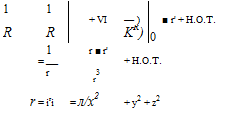
As in the 2D case, the kernel function 1/R is now expanded as a Taylor series about the origin r’ = 0, this time using compact vector notation.

Подпись: 1 1 + VI — ) ■ r' + H.O.T. R R KR) 0 1 r ■ r' = — + H.O.T. r r3 r = iri = л/x2 + y2 + z2 (2.102)

Подпись: the corresponding 3D source-

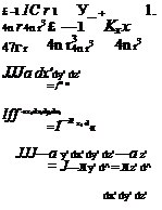
3D Far-Fields Подпись: £ Kx K. Подпись: (2.103) (2.104) (2.105) (2.103) (2.107)

Substituting (2.102) into (2.100) and dropping the higher order terms gives far-field approximation.

The second integrals in (2.104)-(2.107) would be used for the case where the starting source distribution is a filament Л(е) rather than a volume source density. Like in the 2D case, a 3D doublet strength K is a vector whose three components depend on the chosen axes. Its being a vector is also what allows (2.103) to have its coordinate-independent form.

2D far-field observations

A number of observations about the 2D far-field expansion can be made.

• It is rather fortuitous that the airfoil quantities which are of the most interest for engineering — lift, drag, moment, area and thickness — are also the quantities which are needed to estimate the velocity field far from the airfoil.

• All the Vff terms in (2.79) after Vo decay to zero with increasing distance r, so very far away we have Vff ~ Vo as expected. However, for moderate distances from the airfoil, the far-field terms give a much better approximation to the actual V.

• The various far-field terms in (2.79) after Vo have different rates of decay with distance. The Л and Г terms decay as 1/r, while the kx and kz doublet terms decay as 1/r2. In practice this means that at sufficiently large distances, the doublet terms can be dropped from the expansion with little loss in accuracy. Conversely, when sufficiently close to the airfoil the doublet terms may very well dominate. [1]

Far-field effect of lift’s pitching moment

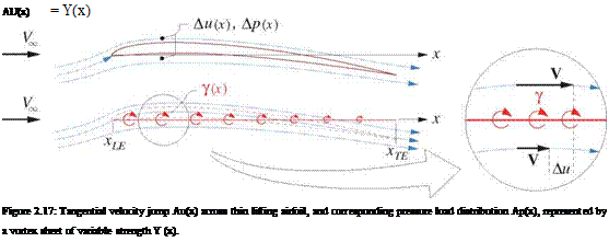
Подпись: AU(x) = Y(x) Figure 2.17: Tangential velocity jump Au(x) across thin lifting airfoil, and corresponding pressure load distribution Ap(x), represented by a vortex sheet of variable strength Y (x).

Again following the thin airfoil theory model of Appendix D, the lift distribution on a thin cambered airfoil can be represented by superimposing the freestream with a vortex sheet placed along the chord line. As shown in Figure 2.17, this results in a jump in tangential velocity equal to the local sheet strength.

The corresponding pressure jump from Bernoulli’s equation is

Ap(x) = Іp [(Ко + Au/2)2 – (Ко – Au/2)2 ]

= pV, AU

= pV, Y (2.90)

which is in effect a local Kutta-Joukowsky relation. The pitching moment/span of the airfoil about the origin, defined positive nose up, is then obtained by integrating this loading with the moment arm —x.

rxTE (‘ xTE

M0 = —Ap x dx = pVo —Y x dx (2.91)

xLE xLE

From the Kz definition (2.83), with A = 0 for this case, we also have

xte

kz = —Y x dx (2.92)

xLE

where again x has been used for both x’ and s. Comparing (2.91) and (2.92) gives the z-doublet in terms of the pitching moment/span, or equivalently in terms of the pitching moment coefficient cm0 about the origin.

Hz = ^7- = 7C2 Ко Сто (2.93)

pV, 2

It’s important to note that M0 is defined about the origin of the far-field coefficient integrals (2.74)-(2.77). This is also the same location that is used to place the far-field singularities, and in particular the vortex. If a moment M^ef about some other location xref is to be used to calculate Kz, it’s necessary to derive the equivalent M0 from it by using the moment-reference shift relation.

Mo = Mr’ef – XrefL (2.94)

or cmo = cmref – °^-ce (2-95)

This M0 or cm0 can then be used to obtain kz from (2.93) as before.

2.11.3 Doublet orientation

The x and z doublet expressions (2.89) and (2.93) have been derived for the case where the freestream is along the x axis. For the more general case where Vo has an angle a relative to the x axis, these doublet expressions actually give the streamwise and normal doublets relative to the freestream direction.

K8 = V^A^l + ^-J (2.96)

Kn = ^c2I4cmo (2.97)

The corresponding cartesian kx and kz are then obtained from these by a rotation transformation.

Подпись: KX = KS cos a — кп sin a = KZ = KS sin a + кп cos a =u w

oo oo

Kstz—– Kn~F~ (2-98)

wo uo __

K’S-^—– h Kn-— (2.99)

In general, a doublet strength is a vector к whose components depend on the orientation of the chosen coordinate axes. These components also obey the usual transformation relations due to axes rotation.

Far-field effect of thickness

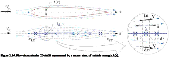
Подпись: Figure 2.16: Flow about slender 2D airfoil represented by a source sheet of variable strength A(x).

Using a simplification of the models presented in Appendix D, the flow about a non-lifting thin airfoil of thickness distribution t(x) can be represented by superimposing the freestream with a source sheet on the chord line, as shown in Figure 2.16. The required sheet strength X(x) is determined by mass conservation applied to the local control volume.

The total velocity is required to be tangent to the top and bottom of the control volume, since that lies on the airfoil surface. Using the 2D version of result (2.39), the net outflow from the source sheet inside the control volume is therefore equal to the volume flow difference between the left and right faces of height t and t+dt. This gives the required source sheet strength distribution.

A dx = V■ n dl = Vco(t+dt) — V» t = V» dt

Подпись:dt

A(.t) — 14 ~r~ dx

This is the same as result D.17) obtained for the general airfoil case, so the assumption of a non-lifting airfoil is justified here. The source sheet extends over xLE … xTE (rather than say 0… c) since x = 0 is the chosen location where the far-field singularities are to be placed, as indicated in Figure 2.15. This is not necessarily the leading edge.

From the Kx definition (2.82), with 7 = 0 for this case, we have

/■XTE Г XTE dt

k, x = —Xx dж = Ко / — — x da: (2.87)

xLE xLE dx

Подпись: Т/ ГТЕ dt A Ат = Ко ~—XdX xLE dx Подпись: — Vv tx Far-field effect of thickness Подпись: xTE t dx xLE

where x has been used for both the sheet geometry x’ and the integration coordinate s. The last integral above can be integrated by parts.

The first term on the right vanishes since t(xLE) = t(xTE) = 0 at the leading and trailing edges, and the rightmost integral is the airfoil area A = t dx. This gives a simple result for the x doublet strength.

Kx = VV A (2.88)

This result is strictly valid only if the airfoil is thin, which is required for accuracy of the source sheet model. For airfoils of moderate thickness, a better empirical estimate is

Far-field effect of thickness1 + (2.89)

where tmax is the maximum airfoil thickness and c = xTE – xLE is the airfoil chord.

2D Far-Field Approximations

The lumping process described in Section (2.3) made ad-hoc simplifications to the kernel functions, which introduced some unknown amount of error in the resulting simplified velocity fields. In this section the kernel function approximation will be made more precise by using a Taylor series. This will give the option of increasing the accuracy of the lumped model, and will also give insight into the behavior of the far-field, or flow-field far from the body. The detailed derivation will be performed for the velocity potential in the 2D case for simplicity. The corresponding 3D results will be summarily presented in the next section.

2.10.1 2D source and vortex distribution far-field

-JJ(* In R-

ІП л/(x — x’)2 + (Z

2D Far-Field Approximations

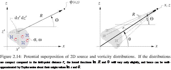
By combining and recasting (2.50) and (2.53), arbitrary distributions of source and vorticity in 2D are seen to have the following perturbation potential field p, as sketched in Figure 2.14. The ln R and 0 kernel functions are defined for convenience.

Подпись: are compact compared to the field-point distance r, the kernel functions ln R and 0 will vary only slightly, and hence can be well-approximated by Taylor series about their origin values ln r and 0.

where H. O.T. denotes higher-order terms with, z, z, x /3, etc. Substituting these Taylor series into the <p(x, z) integral (2.70) above, and rearranging gives

Подпись: + 2D Far-Field Approximations Подпись: 0 Подпись: —az/ — wx') dx/ dz/ Подпись: + H.O.T. (2.73)

2ж tp(x, z) = ff jcr^lnr — Z-x’ — 4-2^ + u) (^—6 – + ~2 z’^j + H. O.T. j ёж’ dz’

with (2.73) being the result after the powers of x and z are collected and taken outside the x/z/ integrals. In terms of the convenient shorthand definitions

Л =

a dx/ dz/

(2.74)

Г =

fj w dx/ dz/

(2.75)

Kx =

jj {—ax’ + wz/)

dx/ dz/

(2.76)

Kz =

(—az/ — wx/)

dx/ dz/

(2.77)

equation (2.73) is a far-field expansion for the perturbation potential

Подпись: (2.78)Л Г кх x kz z

LO(x, z) ~ ,z) = — nr – ——- 6 +———- FT +—— FT

* 2тг 2тг 2тг г2 2тг г2

Подпись: V(x,z) — Vff(x,z) 2D Far-Field Approximations Подпись: z2) Z Подпись: (2.79)

which is approximate because the higher-order terms have been dropped from the Taylor series. Taking the gradient and adding the freestream part gives the corresponding far-field expansion for the total velocity.

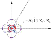
Replacing the exact velocity V(x, z) with the approximate Vff(x, z) is equivalent to replacing the a and w distributions with the corresponding Л, r, Kx, Kz, filaments as indicated by Figure 2.15. These Л and Г are

equivalent to those obtained by the lumping procedure described in the previous sections. However, the added doublet kx and kz terms are new, and can be considered as corrections for the errors due to lumping in cases where the the chosen lumped source and vortex location is offset from the centroids of the a and ш distributions.

2D Far-Field Approximations

2D Far-Field Approximations Подпись: a, m Подпись: x 2D Far-Field Approximations Подпись: x

z

Figure 2.15: Far-field approximation obtained by replacing a(x, z) and w(x, z) distributions or sheet Л(s) and j(s) configurations with the much simpler filament singularities.

For cases where the starting distributions arc source and vortex sheets with strengths A(s) and 7(s), the

far-field coefficients would be defined as

Л =

f Л ds

(2.80)

г =

f y ds

(2.81)

kx =

1 (-Лж’ + jz’)

ds

(2.82)

Kz =

1 Ї. r. . / /

(-Лг’ – jx’)

ds

(2.83)

where the parametric functions x'(s), z'(s) specify the sheet geometry or geometries. The integrals are eval­uated over all the sheets present.

Application of the far-field potential or velocity expressions (2.78) or (2.79) requires knowing the values of the coefficients Л, Г, kx, kz. However, obtaining these from their definitions (2.80)-(2.83) is not possible in the typical situation where the field stregths a, ш or sheet strengths Л, 7 are not known without addi­tional information or modeling. The subsequent sections will describe alternative means for computing the coefficients from other relevant properties of the aerodynamic body.

2.11.2 Far-field effect of lift and drag

As derived in detail in Appendix C, the far-field vortex and source are related to the airfoil lift/span L’ and drag/span D’, or equivalently to the 2D lift and drag coefficients a and Cd based on the airfoil chord c.

T!

1

г =

(2.84)

pVco

2

n1

1

Л =

(2.85)

pv^

2d

Relation (2.84) is the well-known Kutta-Joukowsky lift theorem. Relation (2.85) is perhaps less familiar, but can be considered as the complementing theorem for the drag. Note that unstalled 2D airfoils typically
have Cd ^ C and thus Л ^ Г, and hence the vortex term dominates the source term in typical airfoil far-fields. In contrast, the source term is dominant for 2D bluff-body flows which typically have large drag and comparatively little or no lift.

Modeling Non-uniqueness

In any given practical application, the flow-field representation via sources or vortices is non-unique, in that different source, vortex, and freestream combinations can give the same velocity field. For example, the source sheet superposition (2.64) and the vortex sheet superposition (2.67) can both represent exactly the same (non-lifting) flow-field about the body. There will be a different velocity within the body, but that is physically irrelevant.

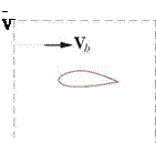
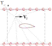
The non-uniqueness extends even to the freestream component of the flow-field. For example, in the general velocity superposition (2.3) the freestream can be represented either as a specified constant, or via infinite source sheets or vortex sheets, as sketched in Figure 2.13. Using a constant added Vb to represent a uniform flow is of course the simplest and the preferred approach in applications.

This representation non-uniqueness gives rise to many different possible types of panel methods, based either on source sheets, or vortex/doublet sheets, or both. Katz and Plotkin [4] give an overview of many such alternative formulations.

Modeling Non-uniqueness
Подпись: Y
Modeling Non-uniqueness

Figure 2.13: Three methods for imposing a uniform velocity (e. g. to represent a freestream V) on the region of interest inside the dashed box: via the uniform added velocity Vb, via two infinite source sheets, and via two infinite vortex sheets. All are valid, but using V is simplest. The three representations also have different velocities outside the dashed box.

Flow-Field Modeling with Source and Vortex Sheets

The representation of low-speed aerodynamic flow-fields using source, vortex, and doublet sheets, when possible, is attractive for a number of reasons.

• In a typical aerodynamic flow with thin viscous layers, very little accuracy is lost when vorticity ш in the layers is lumped into vortex sheets 7 placed on the body and wake surfaces. This is equivalent to the usual inviscid-flow approximation. Chapter 3 examines this model’s limitations and gives modifications to greatly improve its accuracy for cases where the viscous layers are not very thin.

• Only the body surfaces and possibly trailing wake surfaces need to be geometrically defined. In contrast, directly defining a velocity field V(r) requires construction of a space-filling grid throughout the flow-field.

• Numerical panel methods, which employ the sheet representation, require roughly 1/100 fewer un­knowns than corresponding grid methods for any given level of accuracy.

• In cases where the velocity jumps aV or potential jumps Ap across the sheets are known, the source, vortex, or doublet sheet strengths can be computed immediately. The defining relations are derived in Appendix B, and restated here:

Подпись: (2.61) (2.62) (2.63) A = n ■ AV

7 = П x aV

p = Ap

2.9.1 Source sheet applications

A source sheet can be used to exactly represent the inviscid low speed flow about a non-lifting body, as sketched in the middle of Figure 2.10. The sheet is placed everywhere on the surface, which together with an added freestream defines the total velocity field.

Подпись: V(r)Flow-Field Modeling with Source and Vortex Sheets

Flow-Field Modeling with Source and Vortex Sheets

(2.64)

Подпись: V(s/,Q+) ■ n(s,£) Подпись: 0. Подпись: (2.65)

For the usual impermeable body, this velocity must be tangent to the body surface everywhere. Setting the field points just outside the surface at r = (s, i, 0+), this requirement is

Подпись: 1 4n Flow-Field Modeling with Source and Vortex Sheets Подпись: —V ■ П(s,l) Подпись: r = r(s,i,Q+) (2.66)

Substitution of (2.64) into (2.65) results in

which is an integral equation for the unknown sheet strength (s, i). In practice, an approximate numerical solution can be obtained by a panel method, which discretizes the surface into a large number of small panels, and determines a piecewise-constant value of A over each such panel, such that equation (2.66) is satisfied at one control point on each panel. These A values can then be substituted into (2.64) which allows numerical calculation of the local V at any chosen point r, together with the local pressure via Bernoulli’s equation (1.109). This thus defines the flow-field. See Katz and Plotkin [4] for the extensive details.

2.9.2 Vortex sheet applications

Source sheets have the disadvantage that they cannot by themselves represent a lifting flow. This problem can be addressed by switching to vortex or doublet sheets, again placed on the body surface, as sketched on the right side of Figure 2.12. In 2D, the velocity of a vortex sheet plus freestream has the following form.

vw = F 17W y|Xr(r~f ds + V. (2.67)

Подпись: 1 2vr Подпись: yx (r — r7) • П , 7U) І її2 dS | r — r'2 Подпись: -V • n Подпись: (2.68)

Like in the source-sheet case, the requirement of flow tangency V ■ П = 0 gives an integral equation for the vortex sheet strength.

In addition, it is also necessary to impose a Kutta Condition to model the smooth flow off the trailing edge, which is what’s seen in a real viscous flow. In the vortex sheet model this requires that the summed sheet strength of the upper and lower surfaces be zero at the trailing edge.

Подпись: (2.69)YTEupper + ‘7TE lower 0

The solution for the unknown y(s) can be again obtained by a panel method.

Vorticity in high Reynolds number flows

The Helmholtz vorticity transport equation (1.95) dictates that an aerodynamic flow which is uniform up­stream will have zero vorticity everywhere, except in boundary layers and wakes where the action of viscous stress is significant. As sketched in Figure 1.9, at high Reynolds number these vortical regions are thin com­pared to the body dimensions, which makes them natural candidates for lumping into sheets or filaments with only a small loss of accuracy. Figure 2.12 shows such an approximate representation of an airfoil flow-field via a variable-strength vortex sheet placed on the airfoil surface. In this vortex sheet model, the irrotational inviscid flow extends all the way to the surface. Note also that in the 2D case there is no need to place a vortex sheet on the wake, since the net vorticity integrated across the wake is essentially zero. Chapter 3 will examine this flow-field model in more detail, and improve it for cases where the viscous layer is not particularly thin.

Sources in compressible flow

In a compressible flow, with significant density variations, the source distribution a within the flow-field will in general be nonzero. This can be seen by computing a using the steady continuity equation (1.33).

V-(pV) = 0 pV – V + Vp ■ V = 0

V-V = (7 = –Vp-V (2.58)

p

Hence, a is nonzero wherever the density gradient has a component along the velocity vector. In the ir – rotational part of the flow outside the viscous layers, the density gradient is uniquely related to the speed gradient via the isentropic p(h) relation (1.69), and the adiabatic flow assumption of a constant total enthalpy

ho.

Подпись: (2.59)Vp _ J_Vh _ V(h0 – h2V2) _ V(^V2) _ VV

p у—1 h a2 a2 a2

Подпись: a Подпись: W 2 ' Подпись: -2 VV 2 Подпись: 2 ds Подпись: (2.60)

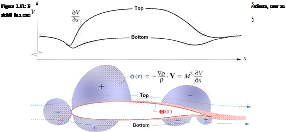
Inserting this into (2.58) gives an alternative relation for a in terms of the streamwise speed gradient and the local Mach number,

where s was assumed to be parallel to V, with s being the arc length along a streamline. Figure 2.11 shows the typical positive and negative a field source distributions in the vicinity of a high-speed airfoil.

Sources in compressible flow

The source-superposition integrals (2.4) or (2.23) still correctly define the velocity field from the a field in this case, and indeed will be used in Chapter 8 to qualitatively investigate and explain compressible-flow behavior. However, because the a distributions near the airfoil are not necessarily compact and close to the airfoil, they cannot be lumped onto the airfoil surface as source sheets without seriously degrading the accuracy of the resulting velocity field. Hence, a must be treated as a volume quantity which makes the evaluation of the superposition integrals (2.4) or (2.23) computationally demanding.

A major consequence here is that quantitatively representing a compressible flow-field with sources and vortices is computationally cumbersome and quite impractical, at least in 3D. For this reason, CFD methods used for calculation of compressible flows typically use space-filling grids as shown in Figure 2.1 on which V(r) or <^(r) are defined by interpolation, and a or ш are not explicitly considered.

One exception is the case of small-disturbance compressible flows where the velocity everywhere departs only slightly from the freestream. In this case the effects of the nonzero a field can be captured by the Prandtl-Glauert coordinate transformation, which will be addressed in Chapter 8.