Category FLUID-DYNAMIC LIFT

PITCHING-MOMENT CHARACTERISTICS

The center of lift of a thin and straight foil section is theoretically at 25% of the chord. Actually, the boundary layer changes this condition somewhat and as soon as there is camber involved, the mechanism of longitudinal moment is different altogether.

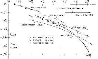
ZERO-LIFT MOMENT. For positive amounts of cam­ber, the component Cmo (in equation 22) is always negative. This means that the bent-down trailing edge tries to lift that edge up, in a manner similar to that of a wing – or control flap. The value of Cmo increases in proportion to the camber ratio (f/c); and figure 30 shows how the coefficient per 1% of camber, varies as a function of camber position. Tested values do not agree with the theoretical functions. The deviation in­creases, as the thickness ratio is increased above some 12%. Results in the graph are not very consistent. After ruling out theoretical functions and the VDT data, one may say, however, that the most widely used foil sec­tions have a zero-lift moment roughly corresponding to

Cm0 = (0.05 to 0.06) (x/c) (f/сГ/о

PITCHING-MOMENT CHARACTERISTICS

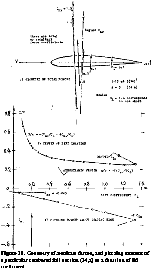
Подпись: Figure 39. Geometry of resultant forces, and pitching moment of a particular cambered foil section (34,a) as a function of lift coefficient.

CENTER OF LIFT. Tiie longitudinal or pitching mo­ment is designated to be positive when it tends to in­crease the angle of attack. The moment is generally made up of two components:

cm = M/q S с = Q., + CJdC^/dCL (22)

where the dots (.) indicate that the reference point is at the leading edge. The quotient C^e/Ct indicates the “center of pressure”, id est the point along the sec­tion chord at which the resultant lift force is acting. The derivative

d9«/dCL = x/c (23)

indicates the “aerodynamic center” of the foil section. When taking the moment about this point, the coeffi­cient Cwac is equal to Cmo and constant (within the operational range of the lift coefficient). To demon­strate what equation (22) means in terms of foil and force geometry, figure 39 was prepared, showing lo­cation and direction of total forces (composed of lift and drag) of one particular cambered section. We see that the location of the resultant force is far back on the wing chord at lift coefficients below 0.1. This ten­dency corresponds to Cmo= —0.04 of the section used. The force then moves forward along the chord, as the lift coefficient is increased, approaching the “aero­dynamic center” corresponding to dCw/dCL. The dis­play os in part (A) of figure 39 has a practical advantage (and it was used in the early years of airplane and/or biplane design for that reason). There is a particular point (or a narrow region) below the foil section where most of the force lines shown, meet and cross each other. When placing the CG of an airplane in that point, wing moments are near zero over most of its speed range (except for very high speeds where the moment cor­responding to Cmo predominates). Modem analysis of longitudinal stability and control is based upon equa­tion (22) however.

Подпись:PITCHING-MOMENT CHARACTERISTICSПодпись:Подпись:REFLEXED CAMBER. Any pitching moment at zero lift is undesirable because it produces structural strain in, and elastic twisting of the wings of an airplane when diving (or when at maximum speed). To reduce the value of Q*0#reflexed camber lines were thus investi­gated (8). The idea was, to camber the section nose into the oncoming flow, while at the same time a bent-up trailing edge would compensate for that camber, thus reducing the pitching moment to “nothing”. Experi­ments in various places confirmed that the moment was reduced as desired. The trailing edge is very important, however, in producing circulation. As a consequence, higher angles of attack (measured against the chord line) are required to obtain a certain lift coefficient, when bending the trailing edge up. In short, the sec­tions developed, were not very efficient as to (L/D) and maximum lift. A better solution was found in the 23012 type sections (33) where most of the mean line is straight, while camber is concentrated near the lead­ing edge (around 15% of the chord, see figure 8). Figure 40 proves that Cmo is reduced to roughly half of what it is in other sections having the same location of cam­ber, and to a small fraction of that in “conventional” sections.

PITCHING-MOMENT CHARACTERISTICS

Figure 40. Pitching moment at zero lift caused by camber, as function of camber location.

3(1o)6

HELICOPTER BLADES. Reflexed sections (without twisting moments) are of interest in the design of rotor blades. A series of 6 such sections varying in thickness and camber, are described in (4-7). Shape and character­istics of two of them are shown in figure 41- Both of them are “better” than the 0012 or 23012 sections, data for which are listed in parentheses, “for most of the flight conditions” of the helicopter considered. The fact that lift = f (angle) is not exactly linear, is the con­sequence of the tail shape and of the drag coefficient varying around CLopt. As intended, the pitching, moment is small, taken around the aerodynamic center. The re­flexion is around 80% of the chord. Camber (near 1/3 of the chord) is between 3 and 4%. The aerodynamic cen­ter is 1% or 2% more aft than in conventional sections; more lift is produced around the leading edge.

AERODYNAMIC CENTER. In symmetrical sections, the due-to-lift component in the second term of equation ( 22) is expected to be all of the pitching moment. This moment is equal to lift times moment arm x. In a cam­bered section, the derivative dCm. /dCi (always nega­tive) indicates the “aerodynamic center”, id est the point about which C^, = Cmo = constant; thus :

Подпись:x/c =r —dCm./dCL (25)

where x = distance (considered to be positive) behind the leading edge. The aerodynamic center is usually evaluated (53,a) from wind-tunnel tests, and tabulated for the many foil shapes investigated. Another point about which the pitching moment can be taken, is the aerodynamic center theoretically expected for zero thickness ratio, id est the quarter point of the chord. Since this point is not necessarily the aerodynamic cen­ter, there usually remains a derivative, and the differ­ential of the location is

Дх/с = — dCm/^/dCL (26)

where the ‘4’ indicates the quarter-chord point. Since the aerodynamic center is at that point only by coin­cidence, we prefer to define the pitching moment about the leading edge. This type of moment is

dCm/dCL= (dCm/Jt/dCL) – 0.25

Подпись: IN OPEN WIND TUNNELS: X ARC, 2 SOURCES (36) + DVL, 3 SOURCES IN (6) A NACA, F’SCALE TU (32) / OPEN, W1 A=6 (28,h) Подпись:Подпись: -0.2-Подпись:Подпись:Подпись: CUSPED SECTIONSПодпись: Figure 42. Pitching moment due to lift, indicating the aerodynamic center (or the neutral point) as a function of thickness ratio.PITCHING-MOMENT CHARACTERISTICSPITCHING-MOMENT CHARACTERISTICSIN CLOSED WIND TUNNELS:

• NACA, V’DENSI TU (31)

° 4-DIGIT, 2-DIM’L (38)

I 63/64 MODIFIED A (37)

CUSPED (CLOSED) JOUKOVSKY – 63/64 2-DIM’L (38)

a AVA, JOUKOVSKY (4,b)

2o 2Г Зо

—»——- 1——– ‘——– 1—–

THICKNESS RATIO t/a % -0.1 -0.3 -0.4

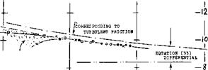
SECTION THICKNESS. Theory expects the distance x in equation (25) to grow with the section thickness ratio. However, as shown in figure 32, the aerodynam ic center is in reality, usually somewhat ahead of 25%; and it does not move downstream as the thickness ratio is increased. As a consequence of momentum losses in the boundary layer, at the suction side, near the trail­ing edge, a high angle of attack is obviously required to obtain a certain lift coefficient. The deficient amount of lift is then produced near the leading edge, so that a positive differential of the pitching moment is obtained. Through the same mechanism, we must also expect that the aerodynamic center will be shifted further ahead when increasing skin friction (section drag coefficient) through surface roughness.

TRAILING WEDGE ANGLE. It is pointed out in section (b) of this chapter, how much shape and thick­ness of the trailing edge affects the lift-curve slope. The same and an even more pronounced influcence is found in regard to the pitching moment:

(a) On the basis of investigations in (53,c) it can be said:

A(dCm/dCL) = 4- 0.004 6° = 4-0.23 tan0 (60) where Є = 1/2 trailing-wedge angle.

(b) It can be concluded that

MdCmQ) ~ 4 2(tan£)(tany) « 8(tan£)(f/c) (61)

where у as in figure 27.

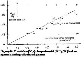
BEVELED TRAILING EDGE. Several modifications of a control flap forming the trailing edge of a foil sec­tion are illustrated in figure 43. It is seen in particular, that the aerodynamic center (represented by dC^./dC^) moves forward, when beveling the edge. Note that dCL/doc is reduced at the same time. The effect of bev­eling is, of course, a function not only of the bevel angle but also of the length of the beveled (chamfered) portion of the chord. Expressing this length by the “thickness’ of the edge as defined in figure 44, a very good correla­tion (50,a) is obtained of experimental results.

PITCHING-MOMENT CHARACTERISTICS

0009 at H0 =■ 3(10)6

o. oo96

о. о9в

0.245

0.0124

о. 101

o.245

O. O105

o. o91

0.215

O. O105

o. o 90

о.200

^Damin

dCj/dc^

dcm/dCL

Figure 43. Influence of trailing-edge modifica­tions (50,a), upon the pitching moment of an 0009 section.

VERTICAL POSITION OF THE AC. As pointed out before, the aerodynamic center is a point of reference for which Cm f= constant. As explained, the location is usually somewhat ahead of 25% of the chord. Figure 45 shows that the point is also somewhat above the section’s chord line. In terms of equation (53) this means that the variation of Cm(CL) is not necessarily a straight line. It is usually possible, however, to find a point some­what above the chord line for which dCm./dCL is con­stant, at least over the “useful” range of the lift co­efficient, id est excluding higher angles of attack, ap­proaching the stall. Consider in this respect the pitching moment including a component due to the tangential force:

Cno -(x/c)CN +- (z/c)CT (30)

(53) Investigation of camber and pitching moment:

a) Thompson, Aerody Center, J Aeron Sci 1938 p 138.

b) ARC, Determination of C andc, RM 1914 (1944).

c) Purser, Trail-Edge Angle, NACA W Rpt L-664

d) McCullough, 4 10% Sections, NACA TN 2177 (1950).

e) Stivers, 4 Airfoil Sections, NACA TN 3162.

(54) Loftin, 66-210 Camber, NACA TN 1633.

Подпись: Ц 6.Л Подпись:Подпись: І0Подпись: �where CN = normal-force coefficient (primarily C(J and Су = tangential-force coefficient. By differentiat­ing this equation against C^, and setting the derivative equal to zero, the location of the aerodynamic center ‘AC’ can be obtained (53). It should be noted that Су ~ C(}5 — Cj_ sine*. Assuming that the section drag co­efficient be constant, the divergence of a tested Ст(С^) function from a straight line, is found (l, b) to be C^. The height ‘z’ of the AC above the chord line (measured in the direction normal to the zero lift line) is then approximately

z/c =. — 7 ACVCl (64)

where AC*, = deviation in the range of small and inter­mediate lift coefficients.

• IB TOT
. * П F8f

– ARC IB (56

z/c #

JT– 30% i/o.

Thickness Ratio

Figure 45. Vertical position of the aerodynamic center
for various types of foil sections.

PITCHING-MOMENT CHARACTERISTICS

h/t = 3 mm ACd = 0. 01 ACd = 0. 02 ACL = – 0.1 AC* – 0. 02

PITCHING-MOMENT CHARACTERISTICSПодпись:

0009

ter.

THICKNESS RATIO. Since the two-dimensional test­ing method (38) is the only one yielding negative values or z/c, we are inclined to disregard these results (21). We can then say that according to figure 45, z/c in­creases with the thickness ratio. The boundary layer developing toward the trailing edge, seems to be re­sponsible for this result. Necessarily, the height ‘z’ has to change from above to below the chord line in sym­metrical sections, between CL =r plus and minus 0.1, or so. The boundary layer accumulation (and/or sepa­ration) switches accordingly, as explained before in con­nection with figures 17 and 18. By comparison, the variation of z/c with the camber ratio f/c, as found in

(31) is very small. It should be noted, however, that the

5- digit sections (with t/c = 12%) also listed in (31) exhibit z/c values more than twice as high as those re­ported for the 4-digit airfoils.

WING ICING and its aerodynamic penalties are re­ported in (45). Typical conditions are as follows:

(a) icing rate

(b) forh/c — 1%

(c) at C^– 0.6 loss of lift (c) pitching moment

The rate (a) is per minute of time 4t As in (b) the ice accumulates “in” the stagnation point of the ООП sec­tion (45,b) at zero angle of attack, to the thickness ‘h Thesattne can be expected for a cambered section when flying at In case (c) there is a considerable flow

around the leading edge. As a consequence, ice deposits itself not only forward, but also upward of the edge, thus forming a ridge across the high-speed flow of air. The maximum section-drag coefficient thus observed (in climbing flight condition) is in the order of 0.04, the loss of lift corresponds to ACl = — 0.2, and the pitch – up moment to &Cm -= 4- 0.04. The time used in these tests, was in the order of Y = 10 minutes, the chord of the 0011 airfoil was c = 2.1 m. With the help of these data, consequences of icing can be estimated for the wing of a real airplane. The combination of insuf­ficient power or thrust, with reduced longitudinal sta­bility can be dangerous.

CHARACTERISTICS OF SPECIFIC AIRFOILS

The generalized characteristics and parametric analysis of airfoils given above is suitable for initial studies of configurations and developing an overall understanding. For specific applications the characteristics of the specific airfoil to be used are needed operating at Reynolds and Mach numbers as near the actual condition as possible. While there have been great strides in the development and use of airfoil theory with high speed computor (40,a, b), actual test results are still preferred for final analysis. The use of the computor has resulted in a new series of airfoils which give important improvements in performance for wings, rotors and any other air-moving device. Since the lift characteristics of two dimensional airfoils are necessary for design of all types of wings the characteristics of specific airfoils and specialized operating conditions will be considered in this section considering only two dimensional airfoil characteristics eliminates the three dimensional characteristics which are covered in the chapters on the various wing types. [29] [30]

CHARACTERISTICS OF SPECIFIC AIRFOILS

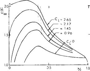
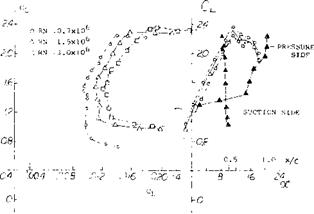
Figure 32. Relative velocity distribution for an airfoil’designed high CLX (FX 74-CL 5 – 140). Dotted lines en­closed observed length of laminar separation bubble.

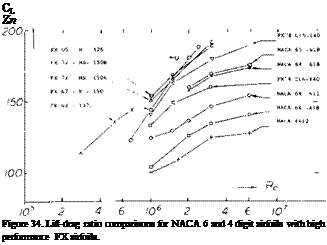
Concave Pressure Distribution. Since the development of the laminar airfoil sections (38,b) a need for higher critical Mach number, improved Cux and lower drag has existed. To satisfy this need new airfoils have been developed by a number of investigators including Whitcomb, Wortman, Liebeck and others (42). In the development of these airfojls, theoretical methods were used to obtain the pressure distribution as well as the prediction of separation of turbulent boundary layer. As discussed in (42,a) the maximum lift is determined by the interaction of the upper surface pressure distribution and the boundary layer. A turbulent boundary layer is needed to obtain the necessary pressure recovery. This is achieved by a concave pressure distribution with a more or less flat forward part, as illustrated on figure 32. The lift characteristics of such an airfoil illustrated in figure 33 show CLX = 2.38 and L/Dx = 140 and a c’u5 /CD of 200 at R = 10c. The L/D for the “concave” pressure airfoils are compared with the 6 series on figure 34 as a function of Reynolds number and prove the value of the design approach.

A IS TRANSITION POSITION

CHARACTERISTICS OF SPECIFIC AIRFOILS

Figure 33.

Drag polar of FX 74-CL5-140 for Reynolds number 1.0, 1.5 and 3.0 (10) .

Подпись: CL Zn Figure 34. Lift-drag ratio comparisons for NACA 6 and 4 digit airfoils with high performance FX airfoils.
CHARACTERISTICS OF SPECIFIC AIRFOILS

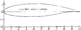
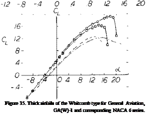
CHARACTERISTICS OF SPECIFIC AIRFOILSПодпись: Figure 35. Thick airfoils of the Whitcomb type for General Aviation, GA(W)-1 and corresponding NACA 6 series. Подпись:

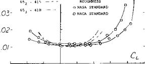
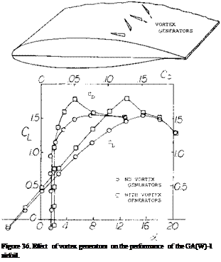
Подпись: The GA(W)-1 airfoil tested with a flat under surface (43,b) resulted in a loss of CLX and with an increase of drag, and illustrates the importance of the cusp on the overall design. Reduction of the lift curve slope illustrated on figure 36 was corrected by vortex generators. Although the drag was also reduced at the higher lift coefficients,, the L/D x was not improved. SURFACE ROUGHNESS. As stated in (38,b) “dust par-ticles adhering to the ‘oil’ left on airfoil surfaces by fingerprints may be expected to cause transition” on laminar- type sections. In realistic operation of engine-powered airplanes, there is plenty of grease, scratches, dust, insects, corrosion of metal and/or erosion of painted surfaces, to precipitate turbulent boundary-layer flow. To account for these possibilities, it is a standard wind-tunnel procedure in (38) to investigate foil sections, and in particular the laminar-type sections, not only in a perfectly smooth condition, but also with a turbulence stimulating strip of carborundum grains (0.01 inch size) spread on both sides over the first 8% of the wing chord (which is c = 24 inches). The consequences of applying this type of roughness, at RN = 6(10)G, are primarily: a reduction of maximum lift, say by 20%, a reduction of the lift-curve slope by a few %, elimination of the laminar low-drag “bucket”.

General Aviation – Airfoils. Airfoils suitable for general aviation aircraft should have a gentle stall characteristic, low drag and fairly high thickness ratios for an improved structure and thus a reduction of wing weight. Based on the general design concepts for low drag supercritical airfoils, a new airfoil was designed using the computer study of (40,a, b) and wind tunnel tests (43,a). The test data of the NASA GA(W)-1, Whitcomb airfoil indicated important improvements of the drag and CL>( characteristics, figure 35, thus validating the theoretical approach. The application of this airfoil with flaps (43,b) shows that a maximum lift coefficient of 3.8 can be achieved with a 30% chord Fowler flap, no leading edge devices and no blowing.

SAILPLANES. As pointed out in (48,a) design conditions for the wing of a sailplane are different from those for a powered aircraft: (a) The aspect ratio is “very” high, in the order of 20 or 25, for glide performance, (b) The Reynolds number is comparatively low, between 1(10) when circling (around 50 mph, at C =0.8) and 2(10) when cruising (at V = 100 mph, and C =0.2), (c) Absence of engine vibration and noise. — These three considerations call for, and make possible, the use of comparatively thick and cambered laminar-type airfoil sections. A large selection of airfoils suitable for sail­planes is given in (42,a, c). The characteristics of a typical high performance airfoil is on figure 33.

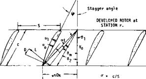
CASCADES: In those applications such as propellers and axial flow compressors, the airfoils effectively follow one another and so operate as a cascade, figure 37. The function of the cascade of airfoils is to create a pressure rise. If the cascade is operating between walls where the axial velocity does not change the pressure rise is developed as a result of the turning of the flow by the cascade. When the spacing between the airfoils is large compared to the airfoil chord, low solidity, and the sections are between walls the lift and drag characteristics approach that of the two dimensional airfoil. When the solidity is high however there is a in­teraction between the airfoil sections and the overall characteristics of the sections change. Cascade airfoil tests are conducted to determine the performance of the sections as a function of stagger angle, solidity and airfoil type. Because of the limited scope of the cascade airfoil data it is desirable to determine correc­tions for the application of two dimensional airfoil data to cascade conditions.

(44) Results on practical-construction airfoils:

a) Tetervin, Helicopter Blades, NACA W Rpt L-643.

b) Doetsch, Waviness 23012, Ybk D Lufo 1939 p 1-88.

c) NACA, TN 428 (fabric), 457 (irregularities), 461 (rivet heads), 724 (rib stitching); 1932.

d) Quinn, Practical Construction, NACA T Rpt 910. [31] [32] [33] [34] [35]

CHARACTERISTICS OF SPECIFIC AIRFOILS

Figure 37. Cascade airfoils and velocity triangle.

Airfoil data is applied in the design of propellers by determining the angle required to correct the three dimensional conditions of the propeller to the two dimensional flow conditions of the airfoil (49e). These angle corrections account for the loading, the blade number, operating condition and span condition in­cluding tip effects. In the case of a rotor operating bet­ween walls the angle correction for applying two dimensional airfoil data can be determined from the equation

<rCL= 2cos(/S/ – cCi)(Ump/ – tan(^ – 2<*i) (22)

where cr = the blade solidity = cB/lTxD = c/s CL= operating lift coefficient – 2/d У = inlet stagger angle <*i = induced angle of attack

The two dimensional angle of attack is found from the equation

a = A ~ W – oft

Here d, is the angle between the rotor blade chord line and the inlet vector, figure 37. In the application of the above equations the lift and drag coefficients are determined from the two dimensional airfoil data at the angle of attack of or. The lift and drag is calculated from these coefficients using the mean velocity vector W to find the dynamic pressure. Good agreement bet­ween the cascade test data and cr CL calculated with equation 22 is obtained for all section cambers and stagger angles up to camber solidities of 1.5

The cascade data (49, f) indicates the lift curve slope decreases with increasing solidity and inlet angle, . Based on these data the slope of the lift curve of the two dimen­sional airfoil, m, becomes, m’, when operating in a cascade and is found from the equation

m’ = m(l + (*.00645/3, – .2352 – -3121cr + .05859a*)

(49) Cascades of foils, vanes, blades, propellers

e) Borst, High and Intermediate Solidity Fans, NASA CR 3063.

f) Emery, et al, Cascade tests NACA 65 sections, NACA TN 1368.

THE MECHANISM OF CIRCULATION IN FOIL SECTIONS

The lift produced by a finite-span airfoil, such as a plate for example, or an airplane wing, can physically be understood as the upward reaction to a downward deflection of a tube or cylinder of fluid having a di­ameter equal to the span of the lifting element. In a foil section (in two-dimensional flow) there is no perm­anent deflection. Therefore, lift or normal force pro­duced, must rather be explained as the result of circulation.

THE MECHANISM OF CIRCULATION IN FOIL SECTIONS

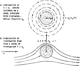
Figure 11. Theoretical flow pattern of circulation around circular cylinder or vortex core. At each and every point, the local velocity and direction corresponds to the geometrical sum of ;(V – p w).

CIRCULAR CYLINDER. Circulation can best be understood by considering the circular cylinder as in figure 11. There are several methods of leading a certain portion of the air flow over the top, one of which is rotation, thus producing the so-called Magnus force to be discussed further in the chapter dealing with “blunt bodies". At this point, we will only make the statement that a “circulating" motion “around" the cylinder is set up by rotation. More fluid passes over the upper and less under the lower side; and the average velocity is increased and decreased, respec­tively. According to Bernoulli’s basic law, the static pressure along the surface of the body is thus reduced on the upper or suction side, and it is increased on the lower or pressure side. The result is a lifting force, id est a resultant of the pressure distribution the di­rection of which is normal (vertical or lateral, as it may be) to that of the basic stream of fluid and/or to the axis of the cylinder. The configuration as in the illustration thus yields a lift coefficient ^ i.4s while the theoretical limit for the flow pattern as in figure 11, would be 4тг ~ 12т.

LIFTING LINE. When reducing the diameter of the Magnus cylinder mentioned above, we finally arrive at a "rotating line.” Together with the surrounding circulating (but not rotating) field of flow, that line represents a vortex (11), and since it develops lift (if restrained to remain at, or if "bound" to its location) that vortex is a "lifting line." The flow pattern of this line, as that of any other vortex, is characterized by the circumferential velocity

w ~ 1/ r ; or: (w r) =. constant (2)

where r = radial distance of the fluid particle considered. As ‘r* increases, ‘w’ reduces (eventually approaching zero). On the other hand, when approaching the center of the vor­tex, the velocity ‘w’ theoretically approaches infinity. Actually, there is always a core within which viscosity (ll, b) slows down the circulating motion, reducing it to rotation (similar to that of a solid cylinder as in figure 11,a).

THE CIRCULATION of the lifting line con­sidered is

Г = w 2 rir in (mVs) (3.)

where (2 гТГ) = circumference of the circle with the radius ‘r’ at which the velocity is ‘w’. When going around the lifting line, or around a rotating cylinder, or around a lifting foil by a 1000 different ways, we arrive at the

THE MECHANISM OF CIRCULATION IN FOIL SECTIONS

THE MECHANISM OF CIRCULATION IN FOIL SECTIONS

TWO-DIMENSIONAL ANGLE OF ATTACK 0<°

o l—— 1—– 1—– 1—– 1—– 1—– 1———-

/о Ю 2.0 Зо

о

Figure 12. Lifting characteristics of a round – edged, id est elliptical section.

integral representing the same circulation as above:

Г — /w ds in (m2/s) (4)

where ‘s’— length of the way once around. This circulation represents the lift produced by any lifting device, or by any section of a wing, around which the integral is taken.

FOIL SECTIONS, as used in wings or anything similar in flatness such as a plate for example, are not lines; і in fact, only a mathematician can produce lift by means of a line. To under­stand the function of a wing section, we might say that at an angle of attack, the pressure side "leans" against the oncoming flow, thus forcing a certain volume of air to go around the usually rounded leading edge (nose), from the lower to the upper or suction side. Along the inclined and possibly cambered upper side, the stream of fluid is then lead down again. The airfoil is thus a device which forces certain stream tubes to go over the top. Theoretically this is not so certain, however. In an ideal, completely non-viscous fluid, the flow would pass around the trailing edge, from the lower to the upper side, and from the stagnation point near the leading edge, around the nose, to a corresponding rear stagnation point, at the upper side, near the trailing edge. The re­sultant lift would be zero, while there would be a "positive" pitching moment, tending to turn the foil to higher angles of attack.

ELLIPTICAL SECTIONS. To illustrate this flow pattern, the lift of an elliptical section having a trailing edge as round as the leading edge, is presented in figure 12. Disregarding some secondary variations of the CL (ex) function, it can be said that the lift-curve slope is simply reduced in comparison to that of a conventional airfoil section. The flow is evidently separated from the round trailing end; and the two separation "points" move, together with the wake, steadily around the end from the pressure towards the suction side, as the angle of attack is increased. Consideration of the pitching moment gives some more insight into the flow pattern. At Rc= 2(10)fe , the center of lift is in the vicinity of 15% of the chord (strong suction forces along the upper side of the section nose, in combination with flow along the convex lower side, possibly to the very end of the section). The lift-curve slope as shown is the minimum. Since separation is a function of boundary layer conditions, the characteristics of the
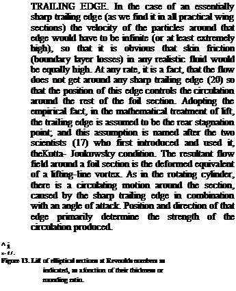
Подпись:

section in ffgure 13 vary with Reynolds num­ber. The lift-curve slope increases slightly as that number is increased. As the number is reduced below 10& , the slope increases also; and it reaches values very considerably above those of conventional foil sections, probably as a consequence of early laminar separation from the lower side, in combination with attached flow around nose and suction side (reattach­ment after laminar separation). This flow pattern is confirmed, at Rc between (3 arid

6) Ш5 , by Cp between 0.05 and 0.02 (which means Cq# up to 0.3), by a location of the lift force in the vicinity of 30% of the chord, arid by a maximum coefficient CLx approaching

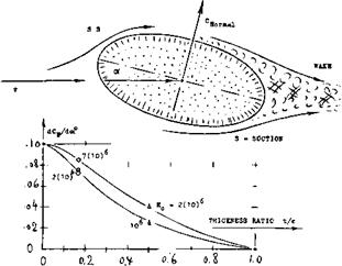
1.0. – As shown in figure 13, the lift or normal force of elliptical sections reduces with their thickness ratio. Naturally, at t/c = 1, that :iis for a circular cylinder, lift (or lateral force) is zero. [23] [24] [25]

THE MECHANISM OF CIRCULATION IN FOIL SECTIONS

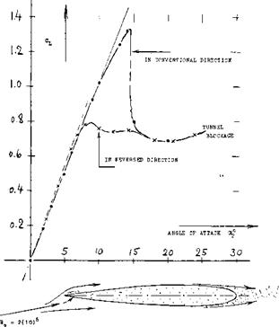
REVERSED 0012. After what is said about round and sharp edges, the lift of the 0012 section as in figure 14- should be expected to be very poor wheri reversing the direction of flow or flight. Surprisingly enough, the section tested has a lift-curve slope not only as high as in the conventional direction, but even slightly higher. There is first the leading-edge flow. As found in many tests with flat plates, a sharp leading edge is "no" obstacle for the flow to get around, and to continue (after a small local separation) along the suction side. To explain the increased lift-curve slope, we may suggest two possible reasons. One is that the round but separated trailing edge acts like a blunt edge (to be discussed later). The other reason may be found in the volume (displacement) of foil plus wake. Increased velocities might thus help to produce higher lift. Of course, the maximum lift coefficient of the section with the sharp edge leading, is but 0.8, in comparison to 1.3 in the conventional direction.-Testing conventional airfoil sections in reverse direc­tion, is not as useless as it may seem at first. In the rotors of helicopters flying at higher speeds, it is quite possible that the in­board portions of the blades are moving against the air, with their sharp edges first.

LIFT COEFFICIENT. In applied arodynamics3, the term “circulation” is not used very much. The lift ‘L’ referred to the lifting area’S’, and to the dynamic pressure ‘q’ of the fluid flow, is represented by the non-dimensional coefficient

CL * L/qS * 2 Г/cV (5)

while the circulation producing the lift, is

/“=CL cV/2 in (mVs) (6)

As a function of the angle of attack ‘oc’, the lift of a flat and thin plate (in two-dimensional flow) corresponds theoretically to

C[_ = 2 IT sinoC (7)

At small angles, the lift-curve slope is

dCL/dcX = 2ir; dCL/da°= 21^/180*» 0.11 (8)

and the "lift angle" (15) is:

do(/dCL= 0.5/rr; or = 90/lT2= 9.1° (9)

This function means that an angle in the order of 9 is theoretically required, in two-dimen­sional flow, to produce a lift coefficient equal to unity, through the use of a plate or any thin airfoil shape.

THE MECHANISM OF CIRCULATION IN FOIL SECTIONS

Figure M. Lifting characteristics of 0012 section in reversed flow (12,d).

THE MECHANISM OF CIRCULATION IN FOIL SECTIONS

0.81 *

NOSE RADIUS r/o 0.24*

Rn = 5(10)°

41*

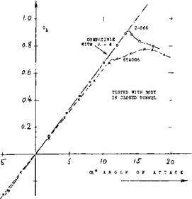
Figure 15. Lift of two 6% thick foil sections, differing in nose radius, tested in tapered wings with A = 4, on fuselage body (29).

SHARP LEADING EDGES. We have mentioned (in connection with the reversed 0012 in figure 14*) that a sharp leading edge can very well produce a high lift curve slope. Theoretically, evaluated from (13,g), the loss of lift, when losing the leading-edge suction peak, is

acl= – (0.25/fr2) – Cl do)

This would be 2.5% at CL= 1, and it would be "nothing" at small lift coefficients. We have evaluated lift-curve slopes as a function of the leading edge radius ratio (r/c) for the 4-digit sections (31,c) as well as for a series of more or less sharp-nosed 6% sections (13,g). The conclusion is, that in a 6% section, about 5% is actually lost when making the leading edge perfectly sharp, as in a double wedge section, for example (having the same location of maximum thickness). This much is indicated in figure 21 as an increase of the lift angle at t/c —0. Sharp-nosed sections (with a cer­tain trailing-edge angle) can also display a lift deficiency (non-linearity) near zero or symmetrical lift coefficient. The losses of momentum at the sharp l’edge evidently cause an accumulation near the trailing edge. For example, double-wedge or double-arc sections as in (13,a, c) not thicker than 6%, already show the non-linearity.

Подпись: (15) (16) Подпись: (17) (18) (20) Подпись:

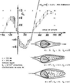
Подпись: Figure 16. Lift of the extremelv thick foil or strut section 0070, tested (18) to an angle of 90%. The lower and upper points plotted, correspond to the time-dependent fluctuations of the separated flow pattern. R’number above critical.

THE NOSE^ADIUS of a foil section is a function of thickness ratio and thickness location. One can change the radius, however, according to equation f 1). As an example, lift and drag of a 6% section are shown in figure 15. There are evidently losses of moment um in the flow when getting around the leading edge of a thin airfoil. The difference in the lift-curve slope of the two shapes tested, is some 7%. The optimum size of the nose radius will also be a function of sur­face roughness and Reynolds number (see later), and of the Mach number (see the chapter on “compressi­bility*’). The maximum lift coefficient must also be considered when selecting a radius for the leading edge; see “maximum lift and stalling".

THE MECHANISM OF CIRCULATION IN FOIL SECTIONS

For “lift angle” (doc/dCjJ see the “wing” chapter. NACA airfoil sections, other than ‘6’ series:

a) See NACA Wartime Report L-345.

b) ‘16’ Series, TN 976, 1546, 2951; TR 763 & 2951.

W. M. Kutta (Bavaria, 1911); N. E. Joukovsky (Zhuko – vskij) “father of Russian aviation” (1847/1921).

Lift (and drag) of the 0070 section, tested by the author, in the two-dimensional water tunnel of Fieseler Aircraft Corporation, 1939.

Influence of the trailing-edge angle:

a) Williams, Cuff Sections, ARC RM 2457 (1951).

See chapter “characteristics of control devices”. DVL, Modified 0015 and (Ю18, see (34,c).

Hoerner, 0070 in Water Tunnel, not published (IS). Batson, 0015 Modified, ARC RM 2698 (1943). Beasley, Lift Reduction, AD-455,356; see (27,d).

The 63 and 64 series sections have almost exclusively been tested in closed two-dimensional tunnels. There results have been disregarded in this text to a large degree. The value of the (38) data is found in the com­parison of the foil sections tested, with each other.

INFLUENCE OF THICKNESS. Thickness means displacement. As a consequence, aver­age fluid-flow velocities along the sides of foil sections are generally increased over those past a thin plate; and their lift-curve slope is theorectically expected to increase with the thickness ratio. As an extreme, we may again consider the circular cylinder. Assuming that we would manage by means of boundary layer control around the rear side, to displace the stagnation points from zero (at the forward side) and from 180° (at the rear side) both down toward 90° (at the lowest point), without losing any momentum, its lift curve slope would be dCL/dcx— 4ir, rather than = 2тг, as in thin foil sections. In theory, therefore, the lift angle (15) reduces (as shown in figure 21) as a function of the thickness ratio.

STRUT SECTION. "Streamline” sections, suit­able to be applied in struts or in propeller blades near the hub, have usually higher thick­ness ratios than conventional foil sections. As an extreme example, the lift coefficient of an 0070 section (18) is presented in figure 16. The lift-curve slope at small angles of attack is strongly negative (!) up to ot^20°. The flow pattern proves that negative lift is the result of flow separation fr. om the upper side of the section. As a consequence of the well – attached flow along the negatively cambered lower side of the section, suction develops there, thus producing negative lift. As the angle of attack is increased, the lower side eventually produces predominantly positive pressures and a correspondingly positive lift. Also note that the maximum lift coefficient at oc=90°, fluctuating between 1.0 and 1.2, corresponds to suction forces developing a – round the section’s nose. – It is shown in (22,b) how the lift function of an airfoil with t/c = 68%, is almost perfectly linear, with a blunt trailing edge (see later). It can also be found in Chap­ter III of “Fluid-Dynamic Drag,” that the maximum lift of a section with t/c =40%, is increased from C^y ~0.8 to 1.15, when blunt­ing the trailing edge to h – 0.4 t. Again, lift as a function of the angle of attack is practi­cally linear. It may not be desirable, how­ever, to have much lift or lateral force in a “strut.” The best method to keep such forces down, is to provide a well-rounded trailing edge.

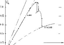
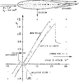
TRAILING-EDGE ANGLE. The shape of all so-called streamline sections (designed for subsonic speeds) is such that the afterbody is more slender than the forebody. Flow separa­tion is avoided or postponed in this manner. Figure 17 presents the lift coefficient of a foil section with thickness location at 40% of the chord. In combination with a thickness ratio of 18%, a trailing-edge angle (included by upper and lower side) of approximately 30° is thus obtained. As a consequence, when rotating the foil out of zero angle of attack, the boundary layer (id est its thickness, but not the material itself) switches from one side to the other. The growth at (and possibly some separation from) the upper side, and the suc­tion of the attaching flow at the negatively cambered lower side, are so strong, that a negative lift-curve slope is produced at angles between plus and minus 1.5°. The positive lift – curve slope (above oc ^ 1.5°) is almost equal to that of the same type of section with the thickness located at 3C?*bf the chord. The later figure 33 includes a different example of trailing “wedge" angle on a comparatively small beveled portion of the chord. While any of the “wild" effect as in figure 17, is not evident, the lift-curve slope near zero lift, is noticeably reduced. Such an effect of the “wedge" angle is particularly known in con­trol surfaces where effectiveness and hinge moment are both a direct function of that angle (as explained in the chapter on “control sur­faces"). In figure 18. it is shown how the lift-curve slope (of symmetrical sections, around cx = 0) reduces, and the “switching" angle (defined in figure 17) increases, as a

HEAVY BOUNDARY LAYER

THE MECHANISM OF CIRCULATION IN FOIL SECTIONS

Figure 17. Lift as a function of angle of attack of a section having a large trailing-edge angle.

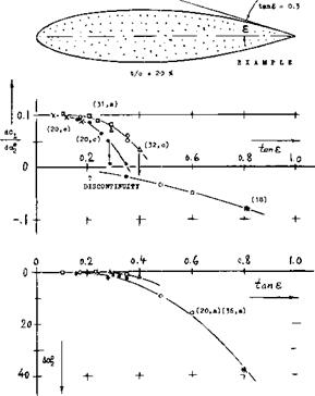
function of the trailing wedge angle (or of the half angles). At tans between 0.3 and 0.4 (that is between 16 and 22°) the slope of the lift seems suddenly to switch from positive to negative. Here again, the Reynolds number (affecting boundary-layer conditions) must be expected to have an influence. As seen in (20,a) for example, “switching" and negative lift-curve slope are not obtained at smaller R’numbers (below 106 ). Since delay and switching do not take place in round-ended (elliptical) sections, it can be concluded that a sharp trailing edge (with a certain wedge angle) is necessary for producing the flow pattern described.

THE MECHANISM OF CIRCULATION IN FOIL SECTIONS

Figure 18. Lift-curve slope and “switching” angle of thick foil sections as a function of the trailing-edge angle as defined in the graph.

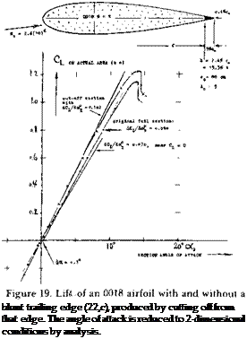
BLUNT TRAILING EDGES have an effect upon section characteristics which is precisely opposite to that of large trailing wedge angles. In fact, the angle included by upper and lower side is naturally reduced when thickening the trailing edge. Figure 19 presents an example where an 0018 airfoil was shortened by cutting off 5% of the chord from the trailing edge. Results of blunt edges similar to this one are generally as follows:

(a) Any weakness of the lift-curve slope in the range of small angles of attack (if any) can be cured by making the trailing edge thick and blunt. This may again be important for con­trol surfaces such as ailerons.

(b) Подпись: blunt trailing edge (22,c), produced by cutting off from that edge. The angle of attack is reduced to 2-dimensional conditions by analysis. The lift curve slope is somewhat increased above that of the same section having a con­ventional sharp trailing edge. In the case of figure 19, the slope (reduced to two-dimen­sional condition) is a full 10% increased over that of the original section. If considering lift (id est, L/q of the wing as tested) rather than the coefficient (referred to span times chord shortened from the trailing edge), we still obtain 5% more lift for the section with the blunt edge than for the sharp-edged original section.

(c) The maximum lift coefficient of the section in figure 19 is noticeably increased. However, if considering CLx-/C^m;n as a figure of merit for a wing, the test does not show any advantage of the blunt-edged (102) over the original section (142). It is only when thickening (rather than cutting off from) the trailing edge, thus keeping the ratio t/c = constant, that a very small improvement of the figure of merit (143), can be found (23,c)for the type of section as in the illustration, for a very modest thick­ness ratio of the trailing edge (in order of h/c = 0.5%, or h/t = 3%). Full-scale, this might be 1 cm; but the edge should be sharp to be of benefit.
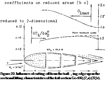
Подпись:Results of another foil section are shown in figure 20. When cutting off a small piece of the trailing edge, the boundary layer accumu­lation as indicated in the illustration is evident­ly cut down too, so that the slope of the lift coefficient (referred to the reduced area) in­creases, to a certain maximum as shown. For similar results on 0012 see (22,a).

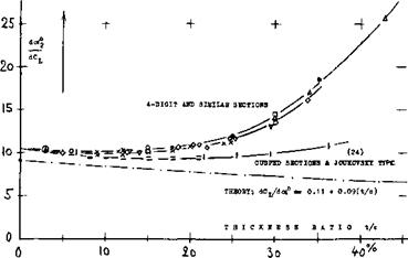
INFLUENCE OF FRICTION. In reality, the lift angle is never as low as predicted by theory (equation 9 ), not even in sections with “opti­mum” thickness and shape. Because of skin friction and boundary layer growth along the suction side of lifting foil sections, the angle necessary to produce a certain lift coefficient is larger than according to circulation theory. The growth (displacement) of the B’layer is usually of such a nature, however, than the straightness of the Cl (o0 function is pre­served for practical purposes, for all but the higher thickness ratios, within the range of

t NACA, 0025/35 IN FST (32,c) П ARC, ООІ5/ЗО, 3(ЮГ (36,a) A FROM VARIOUS OTHER SOURCES <C> AVA, AT 4(ЮГ & З(ЛО)[26] (6)

0 Подпись: Figure 21. The lift angle of airfoil sections as a function of their thickness ratio (15). THE MECHANISM OF CIRCULATION IN FOIL SECTIONSNACA, IN VDT, 3(10)®. (31,с) V ARC STRUTS AT 3(10Г (36,о) x DVL (HOERNER), CLARK-Y (34) – NACA 63/64 IN 2 DIMENS (38)

1 AVA, J0UK0VSKY SERIES (4,b)

Подпись: +Подпись: O' (26,d)Подпись:Подпись: - THEORY FOR t/c = 10 *THE MECHANISM OF CIRCULATION IN FOIL SECTIONSПодпись: cПодпись:

lift coefficients excepting those approaching the maximum. Sectional lift angles are plotted in figure 21, as a function of the thickness ratio. It is seen that the theoretical prediction mentioned above, whereby the lift-curve slope should increase with the thickness ratio (so that the lift angle would reduce), does only come true, say up to t/c = 10%. The boundary- layer growth and the theoretical influence of thickness evidently cancel each other to a large degree, so that the lift angle in the range of t/c between 0 and 12 or 15%, comes out as a more or less constant value in the order of

(dcx°/dCL)2 = 10° (U)

Where the subscript ‘2’ indicates conditions in two-dimensional flow (id est at A =00).

SECTION SHAPE. Although there seems to be an influence of testing technique (l4), con­clusions as to the influence of section shape upon the lift angle in figure 21, areas follows:

(a) Sections with cusped (concave) afterbody contour (such as the 63 and 64 series, in particular) have the highest lift-curve slopes (21) and they maintain a lift angle slightly below 10°, possibly up to t/c = 30% (20,e).

(b) All "conventional" sections (such as the 4-digit series ) with convex afterbody contour and trailing-wedge angles of corresponding magnitude, display a reduction of their lift – curve slope) above t/c = 10 or 12%.

(c) Roughness, even if only applied in form of a stimulation strip near the leading edge, increases the lift angle of sections, particular­ly within the range of higher thickness ratios.

"EFFICIENCY." The loss of lift of afoil sec­tion as against potential theory, can be inter­preted as an effective reduction of the wing chord ‘c’ =a c. Consequently, in two-dimen­sional flow, in comparison to thin-plate theory (equation 2o):

C^- 2 air sincXg ; dCL/do(^= 2 атг ; do<2/dCL= 0.5/air (12)

The commonly used airfoil sections have efficiency factors (30) in the order of a = 0.9. At higher thickness ratios as in figure 21, (dc*/dCj_) increases considerably. Formation of a heavy boundary layer at (and eventually flow separation from) the suction side, displace the outer flow, away from the trailing edge so that the circulation becomes progressively reduced. Theory has tried analysis of this effect; in fact, one author (27) has gone so far as to predict the circulation of a certain foil section from a boundary-layer survey taken at the trailing edge.

10-

IS– (7,a)(2B, h)

Damir

lo*

—y—

Подпись:Подпись:THE MECHANISM OF CIRCULATION IN FOIL SECTIONSПодпись: tПодпись: -1Подпись: —I—Подпись: —f-ROUGHNESS. The section-drag coefficient in­creases with the thickness ratio. Skin friction can also be increased, above that as for smooth surface condition, by roughness. Figure 22 presents doC/dC^ of various "conventional" foil sections having thickness ratios between 12 and 17%, as a function of their minimum section drag coefficient (as tested at small lift coefficients). The lift angle increases con­siderably; a value twice as high as that for smooth condition, is not impossible, provided that skin friction is sufficiently increased by surface roughness and/or other "obstacles," For practical purposes, the slope of the lift angle in figure 22 might be approximated by

A(do<7dCL) = 180 CDimln (13)

(26) * Influence of skin friction on lift, experimental:

a) Betz, Lift/Drag, ZFM 1932 p 277; NACA TM 681.

c) See results function of Reynolds number (40).

d) Batson, B’layer at Tr’edge, ARC RM 2008, 1998

(27) Analysis of lift as a function of drag:

a) Weinig, Lift Deficiency, Lufo 1938 p 383.

b) Sniper, Lift f(Drag), ZFM 1933 p 439.

c) Preston, Boundary Layer, ARC RM 2725 (1953).

d) Beasley, Lift Reduction Due BL, ARC RM 3442

(28) Influence of surface roughness on lift:

a) Wieselsberger, Ringbuch IA9 (Durand IV p 19).

b) See Ergebnisse AVA Gottingen III (1926) p 112.

c) Jones, 0012 &: RAF-34 roughness, ARC RM 1708.

d) Hoemer, 0012 in Wat’Tunnel, unpublished (1939).

e) Hooker, Surface Roughness, NACA TN 457 (1933).

f) Muttray, On Joukowsky Sections, NACA TM 768.

g) Bradfield, With Metal Gauze, ARC RM 1032 (1926).

h) Wood, Corrugated Surface, NACA T Rpt 336 (1929).

(29) Maki, 64A010 Modifications, NACA TN 3871 (1956).

(30) Neely, 44(12 to 24) A – 8 to 12, NACA TN 1270.

(31) Airfoils with A = 6 in NACA V’Density Tunnel:

a) Jacobs, 78 Related Sections, T Rpt 460 (1933).

b) Jacobs, Function of R’number T Rpt 586 (1937).

c) Jacobs, Various Corrections, T Rpt 669 (1939); this report is the best of the series.

e) Pinkerton, Various Sections, T Rpt 628 (1938).

f) Jacobs, 23012 Type, see references (33,b, c).

(32) Airfoils with A = 6, in NACA Full-Scale Tunnel:

a) Silverstein, Clark-Y Airfoil, T Rpt 502 (1934); section named after Colonel V E Clark (1886 to 1948).

b) Goett; 0009, 0012, 0018 Airfoils, TR 647 (1939)

c) Bullivant, 0025 Sc 0035 Foils, TR 708 (1941).

(33) Investigations and results on 23012 airfoils:

a) Jacobs, FS and V’Dens Tunnels, TR 530 (1935).

b) Jacobs, in V’Density Tunnel, NACA T Rpt 537.

c) Jacobs, Foil Series in VDT, NACA Rpt 610 (1937).

d) NACA, with Flaps, T’Rpts 534 (1935), 664 (1939).

e) ARC, in CAT’, RM 1898 (1937); RM 2151 (1945).

f) Doetsch, In DVL Tunnel, Ybk D Lufo 1939 p 1-88.

(34) Airfoils as tested in the “large” DVL wind tunnel:

a) Doetsch and Kramer, Lufo 1937 p 367 and 480; also Ybk D Lufo 1937 p 1-69, 1939 p Ї-88, 1940 p [-182.

b) Hoerner, Clark-Y Series, DVL Rpt Jf 208/3 (1940); also in small tunnel, ZWB FB 65 (1934).

c) Collection ol DVL Results, ZWB FB 1621 (194.3).

d) For DVL (and other) results see also ref (6).

e) Pressure Distributions. Ringb Luftf Tech LA,11.

— 6

DISCONTINUOUS DH0P DUE TO LAMINAE SEPARATION (SCHMITZ)

NACA CLARK-Y FST (32,a) ARC (32,a) ft RAF (36,e) AVA WITH t/o = 12* (6) NACA 12 * SECTIONS (6)

І0 [27] [28]

2 – 14

THE MECHANISM OF CIRCULATION IN FOIL SECTIONS

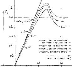
PRACTICAL CONSTRUCTION (44). The boundary layer developing along the chord of foil sections, can be disturbed (made heavier) by skin irregularities (pro – turberances) due to fabrication. A different effect is defor­mation of section shape. Portions of helicopter blades were tunnel-tested (44,a). These blades consist of a solid nose section and a fabric-covered afterbody supported by ribs (with spacings equal to 1/3 of the chord). As a conse­quence of pressure distribution (due to lift) the fabric deforms itself. Because of porosity (leakage) there may also be a negative pressure inside. In helicopter blades, positive pressures may also develop inside, caused by cen­tripetal acceleration. The experimental results as in figure 24 show:

(a) When the fabric is bulging, the lift-curve slope is reduced, probably because of trailing-edge angle and in­creased drag.

(b) For a negative inside pressure of 100 lb/ft (at an estimated dynamic pressure of the same but positive order) the sides of the foil section are somewhat hollow. As a consequence of reduced trailing-wedge angle, the lift-curve slope is as high as that of a smooth and solid 0012 section.

(c) In samples where the fabric tension is not very high, a deformation takes place in such a manner that the pressure side becomes somewhat hollow, and the suction side bulging. The resultant section camber, increasing with the lift coefficient, produces a particularly high lift curve slope, in the order of 0.12 as tested in a closed-type tunnel between walls (21).

(d) The maximum lift coefficient varies corresponding to the lift-curve slope.

THE MECHANISM OF CIRCULATION IN FOIL SECTIONS

14

+

/7 2(10)

In subsonic aerodynamics nearly all wing sections designed for the production of lift have a cambered mean line. The shape of the mean line selected in­fluences the chordwise lift distribution, the zero lift angle, the lift at an angle of attack of zero, the lift at the maximum lift drag ratio and the maximum lift coefficient. The type of mean line used depends on the airfoil series type, and its application.

CAMBER LINES. Mean lines used in the most widely known families of wing sections, are shown in figure 8. These lines are characterized primarily by the location of their tops (in % of foild chord) and by their camber ratio f/c (see figure 1). Although circular arcs are not really used in conventional foil sections, their geometry lends itself to analysis. In particular, the angle at the edges, as in the sketch (figure 27) of such a mean line is

tany" – 2 f/x

where x = distance between f and trailing or leading edge.

ZERO-LIFT ANGLE. In two-dimensional flow, the “symmetricar lift coefficient (see equation 210 for a circular-ar mean line (with x = c/2) is obtained at zero angle of attack. In terms of the angle at the trailing edge, the perturbation or circulation velocity at that edge is

w = Vy; Г— w 2 (с/2)тг = ТГc Vy* in (m2/s) (16) so that the lift coefficient due to camber (at c* — 0) is: — Г/ (с V) = 7ry = 4irf/c (17)

The angle of attack necessary to reduce the C(_ due to camber to zero, corresponds to do^/dC^ — 0.5/77-. Therefore, in a section with circular-arc camber, this angle is theoretically

cxo= -2 f/c = —(360/tt ) f/c = — 1.15(f/c)%

degrees(18)

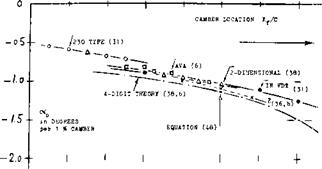
Zero-lift angles are plotted m figure 25, as a function of camber location. Since the angle is related to the tangent to the camber line at the trailing edge, foil sections of the 230 type, having a straight camber line over most of their afterbody, show less negative zero angles than the more evenly cambered 4-digit sections. Foil shapes with thickness ratios exceeding 12%, have zero angles somewhat smaller (less negative) than those shown in the graph, for t/c between 6 and 12%. The angle of zero lift also increases (to somewhat more negative values) as the camber ratio is increased above a few percent.
THE MECHANISM OF CIRCULATION IN FOIL SECTIONS

0 o. l 0-2 o. l ah ».s o. C, o. l

Figure* 25. Alible of attack for /его lift, for camber ratios up to 2 or 3%, as a function of the location of camber along the section chord.

Design CLt, The maximum camber, f, of NACA 1 and 6 series airfoils is generally given in terms of the design CLi, and can be found from the equation

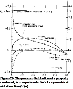
PRESSURE DISTRIBUTIONS are shown in figure 26, for one and the same lift coefficient, one around a straight, and the other for a cambered foil section. The sharp suction peak found at and above the leading edge of the symmetrical section, is avoided bv cambering the edge into the oncoming flow. Doing this (between 1910 and 1920, or so) simple imagination was applied, with the idea of helping the flow to get around the edge (from the lower to the upper side). Meanwhile, it has been discovered that under certain conditions, suction peaks do as follows:

they prevent laminar separation, making the B’laver turbulent; they do not necessarily cause cavitation in hydrofoils; they may even be desirable at higher sub­sonic speeds.

Nevertheless, some small amount of camber, say f/c = (1 or 2)% can successfully be used in the de­sign of wings.

f/c % = 5.515Cj_c (18a)


From equations 18, 18a the angle for zero lift is


THE MECHANISM OF CIRCULATION IN FOIL SECTIONS

Подпись: (35)Подпись: (36)Подпись:Подпись: (18 b)Подпись: Figure 26. The pressure distribution of a properly cambered, in comparison to that of a symmetrical airfoil section (53,e).

cC — -6.34 Сц

Airfoils tested in DVL High-Speed Tunnel:

a) Gothert, In High-Speed Tunnel, ZWB FB 1490-

b) Gothert, Symmetrical Sections, ZWB FB 1505/06.

c) Gothert, Cambered Sections, ZWB FB 1910 (6 Vol).

Airfoil sections reported by British ARC:

a) Jones, 0015 and 0030 in CAT, RM 2584 (1952).

b) Hilton, 18 Sections High Speed, RM 2058 (1942).

c) Williams, Strut Sections, RM 2457 (1951).

d) See also references (5) (6) (7,c) (28,c) (40,b).

e) ARC, Investigations in the Compressed Air Tunnel, RM 1627 (Rnumber), 1635 (RAF-34), 1717 (RAF – 69-89), 1771 (airscrew sections), 1772 (RAF-34), 1870 (Joukowsky), 1898 (23012), 2151 (23012 wing), 2301 (circular-arc backs), 2584 (0015 — 0030).

f) Pankhurst, Aerofoil Catalogue, ARC RM 3311 (1963).

Modifications of the NACA 4-digit series:

a) A modification as to thickness location is presented by Stack, “Tests at High Speed”,

NACA TR 492 (1934); also found in TR 610.

b) Elimination of cusped contour, . . . Loftin, “A”

Series, NACA TR 903 (1948); also TN 1591 к 1945.

Foil sections tested in two dimensions by NACA:

a) Doenhoff, Low-Turbulence Press Tunnel, TR 1283.

b) Abbott к von Doenhoff, Collection, TR 824 (1945); also “Wing-Section Theory”, McGraw Hill 1949.

c) Loftin, At Very High R’Numbers, TN 1945 (1949)

8cRpt 964 (1950); also RM L8L09 with 34 sections.

d) See also reports in reference (37,b).

e) Loftin, Modified 64-010 Section, TN 3244 (1954).

f) McCullough, 0006/7/8 in Tunnel, TN 3524 (1955).

g) 64-X10 Sections, TN 2753,2824,1945,3871; R 824.903.

SYMMETRICAL FLOW. Pursuing the original idea of camber, it is possible to “optimize” the shape for a cer­tain lift coefficient by giving the section such a camber that the flow passes smoothly along both sides of the leading edge, without going around that edge. We will call this condition “symmetrical”, that is in regard to the local flow past the leading point of the camber line. For circular-arc camber (at 50% of the chord) the sym-

THE MECHANISM OF CIRCULATION IN FOIL SECTIONS

metrical lift coefficient is expected to be as in equation (17) so that

CL = 4Tff/c = 0.126 (f/c)% (19)

For camber positions between 30 and 40% of the chord, camber required to make the leading-edge flow sym­metrical, must be expected to be slightly smaller than corresponding to this equation. However, in wings with finite span, stream curvature reduces the effective cam­ber by

A(f/c) = — (0.25/tt) Cj/ A (20)

For practical purposes (with A in the order of 6) the “symmetricar lift coefficient for commonly used foil sections, is therefore ; approximately

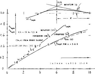
cL<ym= 0.115 (f/c)% (21)

This function is confirmed in figure 27, by results ob­tained from pressure-distribution tests. Selecting the center of the “bucket” formed by their drag coefficient, “symmetrical” lift coefficients can also be obtained for laminar-type foil sections (21).

THE MECHANISM OF CIRCULATION IN FOIL SECTIONS

Figure 27. Symmetrical and optimum lift coefficients as a function of camber, for airfoil sections with t/c between 6 and 12%.

OPTIMUM LIFT coefficients are meant to indicate a minimum of the section-drag coefficient. In “ordinary” foil sections such minimum is not very well defined. Figure 27 leaves no doubt, however, that the optimum are lower than the symmetrical coefficients. As camber is increased, ^ more and more deviates from and below the straight line as for symmetrical flow (equation 52). A sufficient amount of camber is thus found to re­duce the viscous or sectional component of drag, that is at and around a certain lift coefficient (such as Cl =■ 0.3 or 0.4, at which an airplane may cruise from New York to Europe).

THE MECHANISM OF CIRCULATION IN FOIL SECTIONS

Figure 28. Symmetrical and optimum lift coefficients per percent of camber (for camber ratios up to 2 or 3%) as a function of thickness ratio.

THICKNESS RA TIO. Figure 28 shows the value of the optimum lift coefficient per 1% camber, as a function of the thickness ratio. It is seen that as deter­

mined on the basis of section-drag readings, reduces considerably at higher thickness ratios. This result can be explained by the fact that in cambered sections, the weakest part of the boundary layer is near the trailing edge (where the layer is heavy and the pressure gradient positive, thus favoring separation). As a consequence, minimum section drag (and possibly a symmetrical flow pattern) is obtained at lift coefficients smaller than theoretically expected.

“LAMINAR”FOIL SECTIONS are discussed in Chapter VI of “Fluid-Dynamic Drag”. Among the shapes under

(d) in section (A), the ‘64’ series (with maximum thick­ness at 38% of the chord) represents a tentatively ef­fective, yet conservative type of laminar-flow sections. To really obtain the benefit of a section drag coefficient as low as 0.004 (which is half of that of a 4-digit section) certain requirements have to be observed, (a) A mini­mum thickness (say t/c = 10%) is needed to maintain a favorable pressure gradient, (b) The surface has to be kept as smooth as possible, (c) The low-drag “bucket” should be around the cruising lift coefficient. — When giving a ‘64’ section the optimum or the symmetrical camber, the “bucket” moves from zero lift to the de­sign lift coefficient, without losing any or much of its size. For example, the 64-210 section (38,b) is found to have a low drag coefficient at between 0.1 and

0. 3. The ACl – 0.2 is almost doubled (that is, to 0.4) when using t/c = 12%, even at a design lift coefficient Cl*l = 0.4, as in 64-412.

Подпись: Butterfly Wing Small model airplane Large model airplane Albatross RPV Propeller blade chord 4. LOW REYNOLDS NUMBER

The operating Reynolds number is very low for model aircraft wings, birds, bugs and other devices such as wings and propellers used on high altitude remote piloted vehicles. Typical values have been listed (41 ,c) as

R = 7,000

R = 20,000 R= 200,000 R = 200,000

R = 60,000 to 200,000

THE MECHANISM OF CIRCULATION IN FOIL SECTIONS

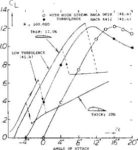
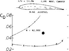
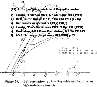
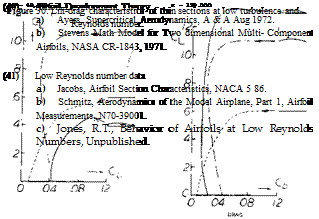
Turbulence Effects. Airfoil test data at low Reynolds number is limited to that obtained by early investigators and for use in conjunction with model airplanes. The systematic airfoil investigations run in the highly turbu­lent VDT (41,a) are considered to be questionable because of the effect of turbulence on the boundary layer. Compared to the data of (41,a) the low Reynolds number data of (41,b) run in a low turbulence tunnel show at R < 100,000 higher levels of drag, lower values of Cimax m^ а lift hysteresis after stall, as illustrated on

figure 29. The reduction of drag obtained at R < 1.05 was anticipated by the work of (41,b).

THE MECHANISM OF CIRCULATION IN FOIL SECTIONS THE MECHANISM OF CIRCULATION IN FOIL SECTIONS

Thickness Ratio and Camber. For the best performance at low Reynolds numbers the thickness ratio should be low and camber high, whereas at R r 1.0 s the higher thickness distribution of a Clark Y or similar airfoil gives better performance, figure 30. This may explain the type of wing section found in nature and the shape preferred by the early investigators. Airfoils with high thickness ratios have much lower values of CLy as shown on figure 31. Here, increasing the thickness ratio from 12 to 20% reduced CLX by one-half. The test in the VDT indicated that large gains can be made by making the flow turbulent. A wire in front of the airfoil can be expected to give the desired flow at low Reynolds numbers.

THE MECHANISM OF CIRCULATION IN FOIL SECTIONS

Figure 31. Lift at R – 100,000 for high and low turbulence at t/c – 12 to 20%.

GEOMETRY AND GENERAL

Before we can evaluate available experimental and other information, we will consider the geometrical shape of foil sections. We will also discuss methods and limitations of testing foil sections.

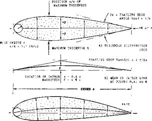
AIRFOILS, or aerofoils as the British say, are more or less flat surfaces producing or exper­iencing lift (or “lateral” forces) in a direction essentially normal to their plane. They have usually a more or less round “nose” or leading edge, and a comparatively slender wedge-like afterbody, ending in a sharp trailing edge. Figure 1 shows the geometric elements of such a section; namely chord and mean or camber line, thickness and thickness location, camber and camber location. Regarding shape, there is a nose radius/ and a trailing-edge “wedge” angle to be considered. Any section can thus be fairly well defined by listing the various dimensions in terms of the chord.

EARLY SECTIONS. Within the framework above, there is an endless variety of shapes that can be designed and tried. In fact, during the last 50 or more years, thousands of sections have been tested, and a smaller number of them have been used in the actual building of air­planes. Early researchers developed wing sections completely by empirical methods, imitating, for example, those of birds. The sections investigated by Lilienthal (2,a) in the past century, and many of those tested by Eiffel (2,b) during the first decade of this century, were comparatively thin, and cambered. They are completely obsolete now, although they are evidently suitable for birds (at Reynolds num­bers below 10*?). A few of these sections can still be found in (7,a); one of them is included in figure 2. As flying was progressing from just “hovering” at maximum L/D, thin sections used in biplanes, were straightened to accom­modate higher forward speeds.

Подпись: high lift seotlon Э»-464 (7,a) t/o - 6.34, «f/о - i(>4, CLx- 1.53 REMINDING of THOSE AS IN BIRDS GEOMETRY AND GENERALПодпись:Подпись:Подпись:Подпись:Подпись:Ro = 4(Ю)5

GEOMETRY AND GENERAL

biplane section RAJ-15 (8,b) HM 888 t/o =. 64, t/o = 34, Cj.^ – 1.20 NOTE SPACE AVAILABLE POR TWO SPARS

section reportedly used in the upper wing of the Wright Brothers’ "Flyer’(3) t/o – 2.24, t/o * 74, flown at CL »«o,6

Figure 2. Examples of early wing sections.

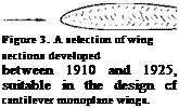
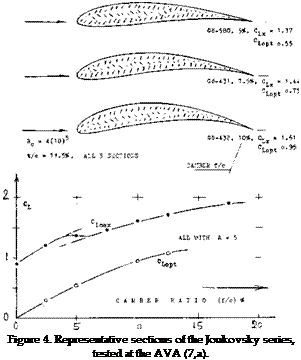
MODERN SECTIONS. Roughly between 1915 and 1925, sections were developed, as par­ticularly reported in (7), eventually to be used in cantilevered monoplane wings. The most successful of these sections, such as Go-535 (a famous sailplane shape) or the Clark-Y repeatedly tested by the NACA (32,a) in thick­ness ratios between 6 and 22% (31,e) or the British RAF-34, had a thickness ratio in the order of 12%, a thickness location around 30% and some camber; see figure 3. The first systematic series of sections named after Joukowsky (4,a) who established the mathema­tical method of producing their shape and predicting their circulation, is similar in shape to those first sections. A number of 36 of these “theoretical” sections were tested at Gottingen (7,a) at Rc= 4 (10)5 , with thickness ratios between 6 and 36%, and with camber ratios between zero and 20%. As shown in figure 4, the tail end of these sections (in their original form) is very thin, the leading edge is round, with the maximum thickness in the vicinity of but 25% of the chord.

GEOMETRY AND GENERAL

RAE-34 (31,e), (12.6/1.8)4 CLx = 1 .49 at Rq = 3(Ю)6

SYSTEMATIC SERIES. To establish some order, several series (families) of practical foil sections have been developed, by syste­matic variation of their geometry.

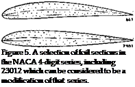
(a) The so-called 4-digit series was published by the NACA (31,a) in 1933, intended to be used in practical design and construction of airplane wings. The maximum thickness in this family is located at 30% of the chord (see figure 6) thus reflecting the earlier empirical result that such sections are most efficient, at the moderate speeds then considered.. Thickness ratios tested (first in the very turbulent Variable Density Tunnel) are between 3 and 25%, later extended to 35%(32,c). Camber ratios are up to 7%, with locations between 20 and 70% of the chord (see figure 25). Selected shapes of this series are shown in figure 5.

An example of this series is

2 4 1 2 — thickness t/c = 12%

Lcamber location at 0.4 chord camber ‘ f; = 2% of the chord

The 4-digit series was later modified (37) as to nose radius and location of the maximum thickness by adding numbers, as for example:

2412-34 — location at 0.4 chord ^indicating the nose radius

As to the nose radius, ‘O’ indicates zero

(c) Another modification of the 4-digit series was introduced by the Germans (34), adding digits to indicate nose radius and thickness location much in the same manner as under

(a) above. Example:

GEOMETRY AND GENERALПодпись: Figure 5. A selection of foil sections in the NACA 4-digit series, including 23012 which can be considered to be a modification of that series. 0012 – 0.55 40—thickness location 0.4 c
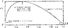
I

one half original nose radius Nose radii were tested between

r c/t2 = 0.275 and 1.10 = (r/t)/(t/c) (1)

where 1.10 indicates the original nose shape of the 4-digit series, and 0.275 one quarter of that; see figure 7.

radius, ‘3’ (as in the example) 1/4 original size, ‘6’ as in the original 4-digit section and ‘9; three times the original radius.

(b) After disappointing experimentation with reflexed camber lines (8) the 5-digit series was developed at the NACA (33). By making the mean line perfectly straight, aft of 0.2 or so of the chord, the pitching moment Cmo was reduced to “nothing.” Regarding thickness distribution, this series is the “same” as the

4- digit type above. The most famous of the family is the

(d) With the advent of higher speeds, it be­came necessary to vary the position of the maximum thickness. Two things are expected to be obtained by moving the thickness back to between 40 and 50% (and by reducing the nose radius at the same time) preservation of lami­nar flow (lower drag) and postponement of the critical speed (Mach number) brought on by compressibility. An example of the most – widely used so-called 6-series sections (38,b) of the NACA is

6 4 – 2 1 2 — thickness ratio 12%

^ design lift coefficient Cl=-0.2 location of minimum pressure at 0.4 c NACA series designation for such sections

GEOMETRY AND GENERALПодпись:GEOMETRY AND GENERAL! 3 0 1 2 — thickness t/c = 12%

Ltwice the camber location at 0.15 chord design lift coefficients 0.2

It must be noted that the geometric camber is replaced by the theoretical “design” lift co­efficient (see figure 27).

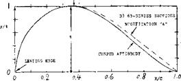
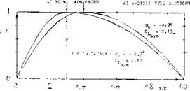
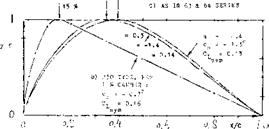
GEOMETRY AND GENERALFigure 6. Thickness distribution (shape) of several NACA systematic series of airfoil sections. [17] [18]

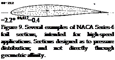
The designation ‘6’ indicates a certain type of the pressure distribution obtained by thickness distribution. This series was tested almost exclusively in a two-dimensional (between walls) closed-type wind tunnel (38) at Langley Field, with minimum pressure locations be­tween 0.3 and 0.6 of the chord (see figures 6 and 9) and in thickness ratios between 6 and 21%. Certain modifications were investigate:! later (37,b) (38, e). An’A’in place of the hyphen, indicates that the cusped tail of these sections is filled up so that a wedge shape results. Sometimes an indication of a particular shape of the camber line is added in the form cf “a=0.6” for example, where ‘0.6’ means one of the 11 mean lines (varying in location) described in (38,b). Without this indication, it is understood that, for example, one of the two camber shapes as in figure 8 has been use:! in designing the section. * Other series are provided for in the NACA system correspond­ing to the first digit between T and ‘8’, which all seem to indicate variations of the pressure distribution. Only a few examples of sections other than ‘6’ have been published (16). The ’16’ series is used in hydrodynamics.

GEOMETRY AND GENERAL

GEOMETRY AND GENERAL

63-012


(35*)

GEOMETRY AND GENERAL

(37*)


0


GEOMETRY AND GENERAL

(41*)


GEOMETRY AND GENERAL

65-012


GEOMETRY AND GENERAL

37 *


GEOMETRY AND GENERAL

CL1 = 0.2


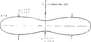
TESTING TECHNIQUES. After learning about shape and geometry of foil sections, it may be useful to see how their characteristics are experimentally determined. The only method of imitating two – dimensional flow, is to test a certain span of a constant-chord foil between parallel walls of a wind (or water) tunnel. Another approach is to test a rectangular airfoil (with an aspect ratio of 5 or 6) in a tunnel, and to correct the results for the in­duced angle (and for tunnel interference) analytically. – A very interesting possibility (9) is illustrated in figure 10. The two large outboard panels of such a wing, induce a component of upwash in the center. Conditions in this center are, therefore, close to two – dimensional. Of course, lift or normal force, moment and possibly pressure drag (or chord – wise force) can only be measured by pressure distribution along center line.


GEOMETRY AND GENERAL

figure 8. Mean or (amber lines of NACA sys­tematic series of airfoil sections.


GEOMETRY AND GENERALGEOMETRY AND GENERALGEOMETRY AND GENERALGEOMETRY AND GENERALGEOMETRY AND GENERALGEOMETRY AND GENERALGEOMETRY AND GENERAL

FLOW DINFLECTION. As far as airplane wings are concerned, their flow pattern is never two-dimensional. Because of the limita­tion of their span, the flow of fluid gets more or less permanently deflected by such wings so that the sections are actually exposed to a curved stream of air. As a consequence, their characteristics such as pitching moment due to camber in particular, must be expected to vary as a function of the aspect ratio. In closed wind tunnels, floor and ceiling more or less resist any deflection (up or down) of the stream by a lifting foil. On the other hand, investiga­tion of wings or airfoils in open-jet wind tunnels (where the stream of air gets too much deflected) can lead to errors opposite in sign to those in closed tunnels. Statistical ex­perience such as in (6) indicates that lift- curve slopes in the NACA two-dimensional closed tunnel set-up (38) are somewhat too high, while those from the open-jet DVL tunnel

(34) are somewhat too low. Reduced to two- dimensional condition, the differentials are in the order of plus/ minus 5%. We have in the graphs given preference to results obtained from airfoils with A = 5 or 6. In other words, we will deal with average wings and not with sections, in the end results. [19] [20] [21] [22]

GEOMETRY AND GENERAL

Figure 10. Planform of a wing (9) designed so

that it experiences, along center line, two-dimensional flow (no downwash).

CHAPTER II – LIFT CHARACTERISTICS OF FOIL SECTIONS

The basic element of every wing or control surface and that of “vanes” and propeller blades, id est of all “lifting” devices (in air or in water), is the foil sec­tion. Lift – and pitching – moment characteristics of such sections, in two-dimensional fluid flow, are pre­sented as follows, as a function of shape, skin fric­tion and Reynolds number. [14] 2 [15] [16]

CHAPTER II - LIFT CHARACTERISTICS OF FOIL SECTIONS

C) COMBINATION OP THICKNESS (A) V/ITH CAMBER LINE (B)

Figure 1. Basic geometry of airfoil sections shown by the example of 0020/4420.

AIRPLANE PERFORMANCE

Methods of performance determination, such as finding the takeoff distance and rate of climb are not the purpose of this book. To point up the significance of certain aerodynamic characteristics that influence the design and selection of the various components of the airplane, some important principles of performance are presented, how­ever. These will include the primary design flight condi­tions of the airplane such as takeoff, cruise, high speed and landing. For more complete analysis of aircraft per­formance there are many excellent sources available (20).

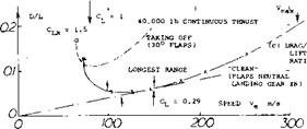
Takeoff. The takeoff performance of an airplane, field length and distance over an obstacle, is directly influenced by the thrust, weight, CLX and drag. To accelerate the aircraft to the takeoff speed, high thrust to weight ratios are needed with a low drag to lift ratio. The speed at takeoff is a function of the maximum lift at the selected flap angle and the wing loading. In the case of large aircraft the rules for safety effectively determine the takeoff distance. As a result, the rate of climb with one failed engine at takeoff speed may be specified and be the determining factor. This is discussed in Chapter VI and determines the lift drag ratio at takeoff as well as the takeoff flap angle setting. The flap angle setting then establishes the lift coefficient at the takeoff speed which is usually

CL (at takeoff) = CLx/1.44 (45)

where Cux is maximum lift coefficient, the airplane in the takeoff configuration with the flaps at the proper angle and the landing gear down.

Climb and Descent. The rate of climb or descent is de­pendent on the difference in power available or required, the weight, velocity and the drag. Thus [12]

Equation 46 shows that a high lift drag ratio is required for a high rate of climb. High rates of descent are obtained at low lift drag ratios and at low or negative thrust conditions. Thus drag spoilers and thrust reversers are sometimes used to achieve high descent rates.

Takeoff Figure of Merit. Since both the distance and steepness of climb after takeoff are important the relative performance can only be judged by a factor that takes both the CL for takeoff and the rate of climb into effect. This may be done by finding the maximum rate of climb after takeoff at a minimum flight speed. Since for a given engine

wc /V = T/W – D/L = С, г С о /CL (47)

since V at takeoff is V ~ /C~L we can establish a figure of merit for takeoff as

FMto-(£ /СІ (48)

When the FMto is a minimum the angle of climb is a maximum. This factor gives an initial indication of the relative performance of different systems.

High Speed is basically made possible by reducing the drag coefficient of an airplane increasing thrust and by flying at higher altitude (in air with lower density). There are some effects, however, resulting from lift to be mentioned here:

a) Leading-edge devices such as slats in particular, are likely to precipitate turbulent boundary-layer flow, be­cause of the gaps and sheet-metal edges left when closed.

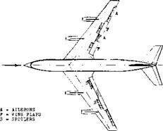
b) Not only the gaps of the trailing-edge flaps and ailerons, but also the arms or tracks supporting, and the devices deflecting them, are bound to contribute to drag.

c) A twisted wing can have a considerable amount of induced drag, even at zero total lift.

d) The horizontal tail surface may be loaded down at high speed, thus producing its own double trailing-vortex sys­tem, and making a higher lift coefficient necessary in the wing.

e) When flying at higher altitude, lift and induced-drag coefficients are necessarily increased. The induced drag (in newtons or pounds) might remain unchanged, however.

(22) Lifting characteristics of birds:

a) Lilienthal, ‘’Bird Flight and Aviation”, Translation London 1911.

b) Holst and Kuchemann, Probleme des Tierfluges, Natur – wi’schaften 1941 p 348.

c) Holst and Zimmer, Vogelflug, J. Ornithology 1943 p 371 & 406.

Drag and Lift**An airplane operating characteristics are determined according to its mass or weight, thrust or drag, and speed. So, while in the rest of this book almost nothing but coefficients are presented, ratios and meters per second are plotted as for example in figure 10. Drag consists of two components. The first, the ‘Viscous” or parasite drag is essentially proportional to the dynamic pressure q = 0.5 f V2. Thus

D0 = CDOTS (0.5 f V2) – ? V2 – vp2

In order to be independent of altitude and density, the “equivalent” airspeed is useful, that is the value “indi­cated” by an airspeed indicator calibrated for sea level density.

where (2 Wlf0 S) = constant for a given airplane in steady flight, without fuel consumption (and disregarding com­pressibility). The dynamic pressure is then

q = 0.5 fcVe =V//16

in ( kg /m-s2) = (N/me)

where f0 has a standard value (- in kg/m3, as in figure 3) and Ve in m/s. The second component of drag is that due to lift. The major portion of this drag is the induced drag. To account for some viscous drag originating as a conse­quence of lift, Oswald (20,a) has introduced a span – efficiency factor which we will designate by a. The drag due to lift:

Ц; = W21 Tf q a b = К (m/Ve b)

in (N = kg-m/s2′) (50)

where m = mass of the airplane (in kg). As a rule of thumb, ЛС0 = 0.01 , so that for A = 6, Д CD /С ql =

20%. For statistical purposes, then a = 1/1.2, and

К = 2 g2/^ f>0 a = 60 = constant

in (m5 /kg-s* ) (51)

Speeds. In terms of the indicated or equivalent speed, me lift of an airplane is

L = (W/ = mg = CL qS = CL 0.5 f0VeZS (52)

The speed corresponding to a given lift coefficient is accordingly:

V = vf2g/ )(m/SC~) =

4 /gm/SC in (m/s) 0 !)

where (m/S) in (kg/m2) = mass loading of the airplane and ^2g[f0 = 4 Vg = constant, in (m^/s^-kg). Considering now a sailplane in calm air (without any supporting up­wind) its “effective” (reduced to sea level) sinking veloci­ty w (in vertical direction) is essentially

w VJJjr = V/Tw7%s(c^7c^) =

s/(2/gpe)(m/S)'(CD/Cj^ ) (54)

Disregarding any possible influence of Reynolds and Mach numbers, all of the right side of this equation is given for a particular airplane configuration. The sinking velocity is found in part (b) of figure 10.

AIRPLANE PERFORMANCE

b

=

131

ft

mean chord = 20 ft

s

=

2433

ft2

horizontal tail = 500 ft2

A

7.1

angle of sweep = 35 deg

w

=

100

kip

completely empty

w

»

300

kip

with maximum load

к

=

30

deg

і flaps during takeoff

T

*

11000

lb

j continuous rated thrust

at

eea level

for

each of 4 Pratt ft Whitney J-1

Ho

=

3 to 6

107

in flight up to 36,000 ft

Figure 9. Planform view and principle data of the USAF КС-135 tanker airplane (prototype of the Boeing 707 airliner) as of 1958 (21).

Landing. The minimum landing speed of an airplane de­pends on the maximum lift coefficient that can be de­veloped. Since the stopping distance after landing is in­fluenced by the touch down speed, it is desirable to have wing systems that produce as high a CUy as possible. Although drag is important in case of an aborted landing, lower lift drag ratios are acceptable with high values of CLX as high levels of power and lower weights are usually encountered during landing, see Chapter VI.

Thus the landing speed will be some factor, say 1.2 times the stalling speed which is

VL = 1.2 (295W/irSwCu>)//z (55)

Where VL is the landing speed in knots and W the landing weight.

Подпись: (a) LIFT/DRAG RATIOПодпись: 200 vПодпись: IOOПодпись:Подпись: (firПодпись: -20- -40 Подпись:Подпись:Подпись: , CVf2D = 2‘2Подпись:AIRPLANE PERFORMANCEEvaluation of KC-135. We are now in a position to derive drag and lift of an airplane and its equivalent velocities (in m/s) either from flight tests or from given drag and lift coefficients. Performance data of the Air Force’s KC-135 tanker (refuelling airplane, prototype of the Boeing 707) are available (26). We are using the flight-tested results, to explain the aerodynamic principles of performance. Di­mensions and data of the airplane (as in 1958) are listed in figure 9. We have assumed W = 200,000 lb, and a com­bined constant thrust of 40,000 lb. Evaluation of the data particularly in (21,a) indicates an extrapolated С^0 = 0.013, and a dC0/dc£ = 0.053. The span efficiency factor is a = 0.84, for “clean” condition (flaps neutral, e landing gear in). The extrapolated minimum drag co­efficient is Cp0 = 0.013, so that approximately
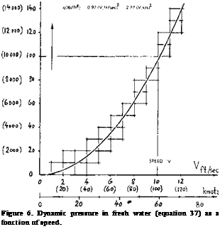
CD =0.013 +0.054 CL[13]

Results are plotted in figure 10, in form of force ratios and equivalent speeds.

Takeoff In case of the KC-135, 30 of flap deflection are recommended for takeoff. A corresponding (D/L) func­tion is shown in part (c) of figure 10. It is seen, however, that after leaving the ground, neutral flaps (and a re­tracted landing gear) provide a much higher rate cf climb.

For Climbing, excess thrust is required. The fastest climb (that is the highest vertical velocity w) is obtained at the speed where (D/L) = minimum, or (L/D) = maximum (as in part (a) of the illustration). We may be fnlcrested, however, in a steep (rather than a fast) climb, say over an obstacle (such as a building). The minimum thrust required to do this for a “clean” airplane corresponds to the minimum of the sinking speed as in part (b) of figure 10. According to equation (55) the optimum speed of lift coefficient is defined by a minimum of the parameter

(C Dicfzy, or (C p /С* );

°r (C 2(f /C(_) (56)

Reasonable numbers are obtained when using (C ^ /CD )• In case of the KC-135, we find at Ve = 100 m/s, a value of 212.

Range. The sailplane mentioned above will travel farthest when gliding along the lowest possible angle, indicated by the tangent from the origin of graph (b). The point found is at the same speed where L/D = maximum, as in part (a) of figure 10. However, in a powered airplane, the miles of distance flown per unit weight of fuel burned, has to be considered. The tangent as in part (c) indicates an opti­mum speed of 150 m/s, for a Cu = 0.29, in the example of the KC-135. Here as in the case of endurance, it has to be taken into account, however, that the weight of the airplane reduces considerably (possibly to half) as the end of the flight is approached (20,g).

Endurance (the number of hours staying aloft with a given supply of fuel) is maximum at the speed where the sinking speed is minimum. This point corresponding again to a minimum of the parameters in equation (56), is found in part (b) of the illustration.

0

IN m/s

EQUIVALENT (INDICATED) AIRPLANE SPEED

ЮО 200 300 400 500^600

SMALLEST GLIDE ANGLE

LONGEST GLIDE LONGEST ENDURANCE AT = 0.66

AND STEEPEST CLIMB

Propeller-Driven Airplanes may have constant engine pow­er available. Even assuming a variable-pitch, constant – speed propeller, neither net power nor thrust are constant, however. Qualitatively, performances are as follows:

a) During the takeoff run, propeller efficiency increases, possibly to near maximum, while thrust reduces.

b) Assuming constant efficiency and constant net power in terms of (T V), maximum climb velocity depends upon excess power (rather than thrust). The corresponding speed V is, therefore, lower than that of a same-size jet-powered airplane.

c) Regarding range, a minimum of (power times time)/(speed times time) = (D V)/V = D has to be found. This will be at the speed where (D/W) = minimum.

d) Both in jet – and in propeller-driven airplanes, maximum altitude (ceiling) and minimum turning circle will approxi­mately be obtained for the point where (C0 /CL ) is mini­mum.

CONSIDERATION OF SIZE AND SPEED OF VEHICLES

Dimensions, weight or mass, cruising speed and density of the medium through which they move, all have an influ­ence upon the geometrical design of dynamically lifted vehicles and their operational qualities.

Square-Cube Law. The volume (weight, mass) of a body grows in proportion to the cube of its linear dimension £ , while its significant area is only S ^((1. As an ex­ample, we may compare the frontal area of a motorcycle (with 1 passenger) with that of a bus (with 50 passengers) or a railroad train (with 500 passengers). It can be found that the aerodynamic drag, roughly proportional to frontal area, is “very” high per passenger for the motor­cycle, and “very” low per passenger for the train. Aero­dynamic efficiency of these land vehicles, thus increases with their size. In the case of an airplane, the significant area is that of the wing (lifting the vehicle), while the volume is the equivalent of its mass, figure 7. Therefore, the mass grows “faster” with size ‘je than the areas of its lifting, stabilizing and controlling surfaces.

Froude Number. In the hydrodynamic design of ships, the Froude number is used to establish similarity between to wing-tank tests and full-scale operation, primarily in regard to wave pattern and wave resistance in calm water (19). The square of this number is the ratio between the inertial or wave-producing forces involved, and the weight (due to gravity) of water and/or vessel. Thus:

Подпись:= гУЛг103 =v*lsi (41)

where p^= )£/g, XZr= weight per unit volume (v=j) of the water displaced by the ship’s hull (displaced volume of water). Note that the vehicle’s weight is W = $ f,

where )T (subscript v) is equal to that of the water (sub­script w).

CONSIDERATION OF SIZE AND SPEED OF VEHICLES

Figure 7. Demonstration of the influence of size and speed upon the relative dimensions of wing and volume of airplanes or hydro­foil boats.

(17) Water tunnels, some of them used for “aerodynamic” investi­gations:

a) See author’s description and results in Fieseler Rpts (1939, 1940).

b) Hoerner, Fieseler Water Tunnel, Yearbk D Lufo 1943 (not distributed).

c) Drescher, Water Tunnels of the AVA, Yearbk D Lufo 1941 p 1-714.

d) Ross-Robertson, 4-Foot Tunnel Penn University, Trans SNAME 1948 p 5.

e) Brownell, Variable Pressure Tunnel, DTMB Rpt 103 2 (1956); see also description of tunnels in TMB Rpt 1856 (AD-607, 773).

(18) Introduction of Froude number in this book, based upon:

a) GabrieUi and von Karman (Mech Engg 1950 p 775, ;:r J. ASNE 1951 p 188).

b) Davidson (Stevens ETT TM 97 & Note 154, 1951; also SNAME Bulletin 1955).

c) Hoerner, Consideration of Size-Speed-Power in Hydrofoil Craft, SAE Paper 5 22-B (1962); reprinted in Naval Engineers Journal 1963 p 915.

d) Froude, Collected Papers and Memoir, Inst Nav Architects (London) 1955. [9]

Hydrofoil Boats. In a boat supported above the water, by “wings” running below the surface, weight or “load” is concentrated upon comparatively small foils. The density of these foils in terms of W/S, or m/S (in kg/m2) is “very” high. Neglecting the comparatively small surface waves left behind these boats when “flying”, the inertial forces are now fluid-dynamic lift (and induced drag). The Froude number may be written in the form of

(v*/gf) or (УЇІЇЛ) or (VK/$7T)

where к is indicating speed in knots, and A = weight of the craft in long tons (representing its mass). These num­bers have a definite influence upon the geometric con­figuration of hull and foils. Since it is desirable to limit the foil span to the dimension of the hull’s beam, the following similarity numbers are statistically found:

(V/v3T~) = for configurations with 3 foils

= for “wing” plus stabilizing foil = for a pair of foils in tandem

While it is possible to make a boat with 3 foils very small, there is an upper limit to the size of operationally feasible hydrofoil boats. The size (span) of the foils required, simply outgrows that of the hull (beam). For a speed below 50 knots, therefore, the largest boat practicable may be in the order of 400 long tons (some 400 metric tons).

Lift Coefficient. When comparing airplanes with each oth­er, interpretation of the Froude number is as follows. The fluid-dynamic force (lift) acting upon the “vehicle” is proportional to (pV S), while the number reflects weight and/or mass forces of the vehicle (subscript ‘V’):

(p/ > = S)/(m/g) = (fj fr) V[10]/g 2 (42)

where the significant area S = і is that of the wing. The subscript ‘a’ indicates ‘ambient’, while is the density of the airplane (in kg/m ). This type of Froude number thus contains a density ratio. The mass density of a conven­tional airplane may be m/V = 200 (kg/m[11] ), in comparison to 1000 for water, and roughly 1.0 for air (at an altitude of 7 km). The density ratio for an airplane is in the order of 200, accordingly. To support the craft by means of aerodynamic lift, the speed in (pV2^2) has to be much higher than that of a hydrofoil boat, say between 200 and 800, instead of 40 knots, for example. Equation (42) can now be rewritten as

(m/g)/( faV2S) = W/^V2S = 2 CL (43)

In other words, the lift coefficient

CL = 2(W/ ?.„V2S) = 2/F/ (44)

is the equivalent of a Froude number. Table 1 has been prepared, containing characteristics of several typical, but extremely different lift-supported vehicles (including birds). It can tenatively be assumed that all of them fly (cruise, climb, keep aloft) at the “same” lift coefficient, say between 0.3 and 0.7.

STOL — airplanes necessarily need to have exceptionally high lift coefficients (possibly up to 8). One example is included in Table 1 on “size and speed”. Structurally, such aircraft must be expected to be limited in size (wing area and span). High lift coefficients are obtained by trailing edge flaps, by propeller-slipstream deflection, and finally by direct application of thrust (as in helicopters, for example). Figure 8 demonstrates how in helicopters, VTOL and STOL aircraft lift is ideally produced, by deflecting a stream tube of air or by direct downward deflection.

TABLE I

Table I, average characteristics (in rough and round num­bers) of various lift-supported “vehicles”, including birds.

m

= mass

(kg)

ft

II

3^

>■0

u

kg/m3

S

= wing area

(m2)

4

= speed

knots

b

= Span

(m)

At

= weight

l’tons

“vehicle”

W(kp)

b(m)

S(m2)

(m)

W/S

VK

Vfit

V(m/s)

cL

РЛ

*7

buzzard (22)

l

1

0.2

0.4

4

18

90

9

0.7

8

3

albatross (22)

8

3

1

1

8

33

130

17

0.5

8

4

small airplane

1,000

10

20

4

50

130

200

65

0.4

11

9

STOL airplane

5,000

20

35

6

140

40

3

21

5.0

20

4

fighter airplane

8,000

18

18

4

440

520

370

260

0.2

160

10

C5-A airplane

250,000

60

600

22

420

480

190

240

0.3

50

10

hydrofoil boat

100,000

10

25

5

4000

40

19

20

0.3

1

8

High Altitude means low density. The value of density at 10 km (30,000 ft, where airliners obtain their longest range) is roughly 40% of that at sea-level. Similarity in the geometric design (wing area in comparison to fuselage dimensions) of two airplanes, one designed for low, arid the other for high altitude (say 20 km as the SST, where density is only some 7% of that at sea level) can only be maintained when keeping the Froude number as per equa­tion (42) constant. A larger airplane will statistically have to be designed for a higher speed; and when flying at higher altitude, the speed has to be higher again. These considerations lead to supersonic cruising speeds (as in the SST).

Control High lift coefficients are usually produced by part-span flaps, while the tail surfaces and particularly the ailerons of an airplane, remain unchanged. Considering a rolling STOL, similar to that in the “size-speed’’ table, but flying at Ct_ = 0.8 for example, the control ‘power’ corre­sponds to the low value F/ = 2.5. Control effectiveness would Thus be only lA that of the fighter airplane. It can also be said that the control surfaces, or their area ratio (control/wing) should be 4 times as high to obtain the same result as with the fighter. The low Froude numbers of the birds as in the table, suggest that they have a highly effective automatic control system, in the form of feel, instant reaction and muscles serving as actuators. They also have variable areas in their wings and tails; and they can twist all surfaces to a degree not found in conven­tional man-made airplanes.

Dynamic Stability. The motions of an airplane, resulting from the combination of fluid-dynamic forces (such as in the tail surfaces, for example) and forces arising in the masses of the craft as a consequence of acceleration (and deceleration) determines the dynamic characteristics (19). The term in the equations of motions accounting for these forces is the relative density, or the ratio of the mass of the vehicle to that of the fluid affected. Therefore, the Froude number as in equation 42 could directly be used when determining dynamic stability. For example, oscill­atory motions of an airplane will be “similar” to those of a properly built wind-tunnel model, when the Froude number is kept constant. On the basis of the F’numbers in Table 1, it can also be expected that a fighter-type air­plane can be very stable.

Advanced Vehicles. Table 1 in this section only presents examples of birds, airplanes and a hydrofoil boat. In reality, there is a wide range of size and speed in each category of vehicle, depending among others, upon power or thrust installed. For example, a fighter airplane is designed for high speed; its Froude number is particularly high, accordingly. Nevertheless, there are statistical trends evident; the average lift coefficient decreases as the size is increased; the Froude number increases as the speed is increased. The speed-size relation is not usually considered when designing an airplane. Power available and speed are

CONSIDERATION OF SIZE AND SPEED OF VEHICLES

(a) Lift produced in wing bу defleotion of a atreaa tube with the effeotlT* diameter equal to the wing span.

CONSIDERATION OF SIZE AND SPEED OF VEHICLES

Figure 8. The origin of lift:

a) produced in a wing by deflecting a streamtube of air,

b) produced by a fan, propeller or helicopter rotor.

a matter of specifications for a particular type of airplane required. To produce this aircraft, is then a matter of structural design, engine development, the introduction of new materials. For ехдтріе, the increase of maximum lift from CL)< = 1.5 (say around 1930) to 7.5 as in STOL airplanes (around 1960 or 1965) is made possible by elaborate structural innovations, such as triple-slotted wing flaps and tilting wing-engine-propeller combinations.

(20) Calculation of airplane performance:

a) Oswald, Performance Formulas and Charts, NACA Rpt 408 (1932).

b) Diehl, in “Engineering Aerodynamics”, Ronald New York, 1928 to 1936.

c) Wood, “Technical Aerodynamics”, McGraw-Hill (1935, 1947) by author (1955).

d) Perkins-Hage, “Airplane Performance Stability Control”, Wiley 1949.

e) Dommasch, “Airplane Aerodynamics”, Pitman 1951.

0 Wood, “Aircraft Design”, Johnson Publishing (Boulder, Colo.) 1963.

g) Breguet, Endurance (1921); see J. Aeron Sci 1938 p 436; see (b).

(21) Characteristics and Performance of KC-135 (Boeing 707):

a) Vancey, КС-135 Flight Tests, Edwards AF Base TR-1958-26; AD-152, 257.

b) Tambor, Flight Tested Lift and Drag, NASA TN D-30 (1960).

Подпись:It is not yet clear where the consideration of size and speed similarity (or dissimilarity) can be of practical value. One example in this respect seems to be the control of aircraft. In very high altitudes (low air density, as in NASA’s more or less ballistic X-15) and/or at low speeds (as in STOL airplanes) aerodynamic devices are no longer sufficient. Suitably located gas jets, coupled with auto­matic sensing and actuating devices, therefore, have to be used. An awareness of the influence of size, speed, densi­ty; and, of course, the anticipation of limitations or diffi­culties such as supersonic effects (or cavitation in water) may prepare the designer for the effort in research and development required, before proceeding with the con­struction of any advanced vehicle, or the introduction of a new mode of lift-supported transportation.

PHYSICAL PROPERTIES OF FLUIDS

The temperature at the freezing point of water (where T = 0 C) is T = 273.15 K, and at the boiling point under sea-level pressure, = 100° C, or = 373.15° K.

Dynamic Pressure. The mass density of air is essentially

?(kg/m ) = p(N/m )/‘R’T(°K) (19)

where ‘R’ = gas constant := 8314/29 = 290 (N-m/kg – K), up to some 90 km altitude, in one of its many definitions. In standard sea-level air, it happens to be that

pc=g/8 = 1.225 (kg/m3) (20)

2_

as listed above. The dynamic pressure q = 0.5 ^ V at sea level is accordingly

qo = (V, m/s) /2.45 = (V, kts)2/9.3

in (N/M ) or (kg/m-s2) (21)

/

/ tQOpOC-

DYNAMIC PRESSURE

q = 0.5 <jQ V2e IN (N/m2) OR (kg-m/s o= 1.225 kg/m2

Подпись:Подпись: (kp/g0m2)

Подпись: Properties such as density and viscosity are presented in chapters I and XIX of “Fluid-Dynamic Drag”. Some of them are presented here again, in revised form. (A) Characteristics of Atmospheric Air Air is the most important element for fluid-dynamic notion. Its properties are simple and consistent: within die range of subsonic (and transonoic) speeds and up to altitudes in the order of 90 km. PHYSICAL PROPERTIES OF FLUIDS PHYSICAL PROPERTIES OF FLUIDS

Яць/ft2) = 4(N/m2)/4

I – GENERAL INFORMATION

-■**

This pressure is plotted in figure 3. Of course, there is some variation between the seasons of the year. As we all know, temperature at the ground may be 15 C lower during a winter day, and 15 ° C higher on a summer day. Atmospheric density may thus be 5% higher or lower. Also considering a possible variation of the barometric pressure in the order of + or -3%, the total variation of density and dynamic pressure at sea level as in figure 3, could be + or — 8%.

Function of Altitude. Aviation is not confined to sea – level operation. In fact, modern airliners cruise at altitudes around 10 km, not to mention the supersonic transporter SST which will do it at some 20 km. Values of tempera­ture and density ratios, standardized for the temperate zones of the earth, are plotted in figures 4 and 5. It is seen how temperature reaches a value assumed to be constant, at Z = 11 km. Density at this altitude is down to about 30% of that at sea level, which could be said to mean that the drag of an airliner be reduced to the same 30%. What is said above regarding temperature and densi ty deviations from the average or standard values at sea level, does not mean, however, that the same differentials would also be found at altitude (11 ,f)^ let alone higher altitudes, that is above some 30 km. It is also not correct to assume that the same differences as at sea level, between the equator and the poles of the earth, would also prevail at those altitudes. In fact, temperatures can be warmer at times and locations where they are expected to be colder, and vice versa.

Viscosity of the Air. The dynamic or physical or absolute viscosity in standard sea-level air is

yU0 = 1.79/105 (m2/s) (22)

for all practical purposes covered in this book, this type of viscosity is independent of pressure. As plotted in chapter I of “Fluid-Dynamic Drag”, it increases with temperature, however. For subsonic speeds (that is, be­tween T = 170 and 500 K) the viscosity of air varies in good approximation, as

o. l Ь

M ~ T (23)

By combination with the density, the kinematic viscosity vr=/^/(> is obtained (in mz/s). Under standard sea-level conditions (see tabulation above) the non-dimensional Reynolds number is then approximately

R, = VJUV V. noof (24)

where V is a suitable length such as the mean aerodynamic wing chord in particular. Of course, at altitude, the abso­lute viscosity has to be reduced as per equation (23), while the density reduces as in figure 4. For example, as Z above 11 km,

1 -9

o.7<=>

F = (0.75) Ao = 0.805 (25)

Considering the density at 11 km to be 30% of that at sea level, we obtain a kinematic viscosity

f = (0.805/0.30>£=2.7v£

for that particular altitude. The important result is that the Reynolds number R^ /vT/7‘, reduces considerably with altitude for a given airplane when flying at the same speed, that is to 1/2.7 = 37%, for example at 11 km. When flying at the same dynamic pressure (which means essen­tially at the same lift, drag and thrust) the speed at 11 km is increased to (1/ 0.3 ) = 1.8 times that at sea level. The Reynolds number is then (1.8/2.7) = 0.67 times that at sea level.

The Speed of Sound is generally

‘a’ = Vdp/d^ = Vk ‘R’ T (26)

where k = c/c =1.4= constant in atmospheric air up to some 100 km, and ‘R’ = gas constant as above. For stand­ard sea-level temperature, the sonic velocity is

‘a’ ^ 340 (m/s) ^ 660 knots (27)

Throughout the troposphere, the speed of sound reduces according to

‘a’ = 20/т7°К) in (m/s) (28)

Disregarding a tiny /decrease of g = acceleration due to gravity, the standardized speed of sound remains constant above Z = 11 km, see figure 5:

‘a’ = 0.867 X = 0.867 (340.3) = 297 (m/s)

For practical purposes, we might memorize this speed to be 1% less than = 300 m/s.

(14) Intensity and characteristics of rain, fog, icing:

a) Brim, Impingement of Water Droplets on 65-208, 65-212, 65AO(04 to 12)% Airfoils at oi = 4P, NACA TN 2952 and 3047 (1953).

b) Brun and Dorsch, On Bodies, NACA TN 2903, 3099, 3147, 3153, 3410 (1953/55).

c) Kriebel and Lundberg, Drag in Particle-Laden Gas Flow, 4 Rpts (1962) for Defense Atomic Supply Agency by Stanford Res Institute; AD-291,178.

d) Shifrin, Microstructure of Fog, NASA Trans TT F-317 (1964).

e) Preston, Ice Formation and Airplane Performance NACA TN 1598 (1948).

f) Gray, Aerodynamic Penalties by Ice on Airfoils, NASA TN D-2166 (1964).

PHYSICAL PROPERTIES OF FLUIDS

PHYSICAL PROPERTIES OF FLUIDS Подпись: • PRESSURE V-2 SOUNDINGS о DENSITY SOUNDINGS Д DENSITY, SPHERE METHOD

Humidity. The amount of water “solved” in atmospheric air is usually small (less than 1% by weight, before va­porizing). Since vapor is lighter than air, the density is reduced (14,f). For example, in standard sea-level condi­tion, 100% vapor humidity reduces density by 0.6%. Hu­midity has other effects upon the air, such as upon tem­perature as a function of altitude. More dramatic results are fog, clouds, rain, snow and icing.

Fog. As stated in (14,d) fog particles are between 4 and 15 microns in diameter; and there are at least 50 droplets in one cm3. The mass ratio is then found to be in the order of 2/10 , which is negligibly small. However, fog reduces visibility to such a degree that even automobiles get into serious accidents.

Rain. Modern airplanes are designed to operate in a com­mon rate of rainfall. As reported in (14,a, b) most rain drops are in the 0.5 to 1.0 mm size range. Their average falling velocity is estimated (see chapter III of “Fluid – Dynamic Drag”) to be in the order of 4 m/s relative to the air, which is 2% of 400 knots of airplane speed, for example. A usual rainfall is said to accumulate between 1 and 2 mm per hour at the ground. The mass content of water in air is then in the order of 1/10^. In “heavy rain”, this content may be tenfold (1 per 1000), and in a cloudburst 100-fold, making the mass ratio equal to 1%. Really small drops would likely be more or less directed by the airflow around a wing, while typical rain drops may directly impact upon the upper and the frontal areas. Consequences are as follows:

a) Due to water adhering to the surface, the increase of the weight of an airplane is estimated to be a small fraction of 1%.

b) The vertical mass flow of droplets possible impinging upon the wing from above, during a “heavy” rain, might be

PHYSICAL PROPERTIES OF FLUIDS

Figure 5. Standardized variation of temperature and Mach num­ber, up to 100 km of altitude, presented in the form of ratios.

(dm/dt) = wpa /1000 (kg/m2 s) (29)

where m = mass per unit wing area and (1/1000) as above. For the velocity w = 4 m/s, and an air density pa =

1 kg/m, the impact pressure of the rain drops might then be

(dm/dt) w g = 16(9.81 >/1000 « 0.16 (kg-s/m* ) = (N/m2)

By comparison, the mass loading of an airplane is between 150 and 300 kg/m2 or a v/eight loading of 1500 to 3000 N/m 2 (or 35 to 70 lb/ft ). The impact of rain considered, would thus not be of any importance.

c) In regard to drag, rain drops will more or less impinge upon the frontal area of an airplane. This type can thus be treated as a free-particle flow (similar to the Newtonian type as described in “Fluid-Dynamic Drag”).

Assuming that the rain drops captured by the frontal area S, of an airplane, lose half of their momentum (that they are accelerated to lA the airplane’s speed V) we obtain

iD = 0.5 V2^S. (mw/ma) (kg-m/s21) = N

(30)

where “w” indicates water and “a” = air. Assuming an effective (capturing) frontal area ratio S./S = 0.1, the incremental drag coefficient may then be

AC0 = (SjS)(fJfa) (nv/ma) (31)

For a constant (mцг/nu) = 0.1%, as in “heavy rain”, the result is ДС0= 0.08. This would be as much as the air­plane’s original drag at CL = 1. According to (14,c) it seems, however, that a portion of the rain drops larger than assumed above, is diverted by the air flow around the wing, for example.

Icing. The formation (deposit) of ice upon the frontal areas of an airplane (such as the leading edge around the stagnation line) can increase weight and drag appreciably. At cruising speed, drag increments up to 80% are reported in (14,e), while the propeller efficiency may be reduced 10 or even 20%.

Wind profiles (velocity w or dynamic pressure as a function of altitude Z above ground) are plotted in chap­ter IV of “Fluid-Dynamic Drag”, up to altitudes Z be­tween 25 and 250 m. Similar data are reported in (15,a). It appears that in properly developed steady wind over a plane unobstructed surface (such as an airfield) the varia­tion is approximately

i/n ’ г/г

w,/w, =(Zz/Z,) ; or q^/qor, =(Z2/Z,) (32)

where n between 6 and 8. At “higher” Reynolds numbers, distributions within turbulent boundary layers usually correspond to w ^ Z/? . Behind obstacles (such as build­ings at the edge of an airport) there is a deficiency of speed. As shown in (15 ,b) a gradient much stronger than that indicated by n = 6 or 8, may then be found above the level of those obstructions. Regarding the climb-out per­formance of airplanes, any positive gradient will help. It seems, however, that when landing into a strong wind (and possibly over an obstacle) the negative gradient can be dangerous. While reducing the airplane speed, thus increasing the lift coefficient, the wind velocity also re­duces, thus possibly leading to wing stalling at angles of attack beyond that for C^x. Airplanes are thus operated at lift coefficients approximately 70% of the maximum to allow for turbulent velocity conditions and control inputs.

(B) Physical Properties of Water

There are “lifting” devices used in water such as rudders and hydrofoils. Properties of water are presented in “Fluid-Dynamic Drag”. They are here given again, in met­ric units.

The Compressibility of water dy/dp, measured in (kg/m3 )/(N/m2) = (kg/mN) = (s/m)2 , is very small in comparison to that in air. As a consequence, the speed of sound ‘a’ = t/dp/dp is in the order of 1440 m/s (4700 ft/sec, 2800 kts) in comparison to 340 m/s (1117 ft/sec, 660 kts), in sea-level air. For example, it takes more than 7 hours for an explosion, say at the coast of Japan, to be “heard” in San Francisco (over a distance of almost 5000 sea miles, or 9000 km). It would only be less than 2 hours, however, to detect the same disturbance by sonar. For comparison, the travel time is in the order of 10 hours by subsonic jet airplane (if non-stop at M = 0.8), and less than 3 hours by Supersonic Transport (at 2000 mph, approaching M = 3).

Dynamic Pressure. The density of sea water is some 840 times that of sea-level air. For all practical purposes, this density can be considered to be constant (to be inde­pendent of temperature and pressure):

p (fresh water) = 1000 kg/m3

In average (Atlantic) sea water, with a salinity in the order of 3.5% (16,c), the density is higher:

p (sea water) = 1025 kg/m3 2.0 lb-sec/ft Corresponding to these densities, the dynamic pressure is

q = 500 g V2 in (N/m2) or (kg/m-s2)

in fresh water

(33)

q = 513 g V2 in (N/m2) or (kg/m-s2)

in sea water

(34)

Using у as above, we also obtain conveniently:

q = 500 (V m/sf in (kp/m2)

in fresh water

(35)

* q = (V, ft/sec)2 in (lb/ft2)

in sea water

(36)

q = 0.97(V2) in (lb/ft2)

in fresh water

(37)

Equation (37) is plotted in figure 6

in fresh water

ex-

pecting that the metric system will be accepted last, in the field of naval architecture.

(15) Characteristics of atmospheric wind:

a) Lettau, “Exploring Atmosphere’s First Mile”, Pergamon 1957; also “Wind” in chapter 5 of “Handbook of Geo­physics”, MacMillan 1960.

b) Stearns, “Atmospheric Boundary Layer”, Univ Wisconsin (1964); AD-611, 209.

c) Am Meteorological Soc, Wind for Aerospace Vehicles, Bull 11 (1964) p 720.

The Viscosity of water, needed for the computation of the Reynolds number, is plotted in chapter I of “Fluid – Dynamic Drag”, in the form of V At the standard temperature of 15 C, the kinematic viscosity is between (1.16 in fresh and 1.13 in sea water)/ К)5 (ft* /sec), which is between (1.08 and 1.05)/106 (m2/s). Contrary to that in air, this viscosity reduces as temperature is increased, that is roughly as

S =M/ f’-l/T6 (38)

Water Tunnels (17). The high density of water makes it possible to obtain high Reynolds numbers in a tunnel built in the same form as that of an ordinary wind tunnel. For example, in a comparatively large, but low-speed wind tunnel we may have:

c =

1

m

wing chord

V =

40

m/s

air speed

q =

100

kp/nZ

dynamic pressure

Rc =

2.8

(10)6

Reynolds number

For operational reasons, the size of a water tunnel might be restricted. We could obtain the following, however:

c –

0.5

m

wing chord

V =

10

m/s

water speed

q =

50000

kp/m2

dynamic pressure

R =

4.3

(10)6

Reynolds number

As in equation (38) the viscosity of water reduces as temperature is increased. Therefore, when increasing the absolute temperature from the standard 288° К to 316 K, that is from 15^ C to 43 C (which is only 4 C more than our blood temperature) the Reynolds number in the water tunnel suggested, can be doubled. A number Rc approaching 107 could thus be obtained. For many pur­poses, we just do not need such high R’numbers; and at a speed, say of 2 m/s the most instructive flow patterns could easily be produced in water by adding a suitable substance. To make the water tunnel still more attractive, its low power requirement is mentioned. For a one meter squared test cross section, the power is approximately

power = 0.5 q 0.25 ^ V3/1000 = V3/4 kwatt

For V = 10 m/s, that would be 250 kwatt; and for 2 m/s, only 2 kwatt. [6] [7] [8]

Cavitation is vaporization (boiling) due to reduced pres­sure. Fundamentals and examples of cavitation are pre­sented in chapter X of “Fluid-Dynamic Drag”. Really pure water (distilled, in a pure container) may not cavitate at all. However, all kinds: of microscopic impurities (such as cosmic dust, particles remaining in drinking water after filtering, tiny air bubbles in the interface of sea water, or plankton) will “always” provide the nuclei needed to start a vapor bubble. The critical pressure at which water at a temperature of 15 C begins to turn into gas (vapor) is less than 0.016 of the atmospheric pressure (= 33 lb/ft2 = 1600 N/m2). So, for practical purposes, we may as well say the vapor pressure p^ is zero.

The Cavitation Number indicates the tendency of the ambient flow to cavitate, when meeting an obstacle:

where q = dynamic pressure, and pa = ambient pressure. At standard sea-level pressure (“at” the surface of open sea water) the coefficient of that pressure (pa – p„) = 2116- 33 = 2083 lb/ft2, is

<ґ – (p – pj/q = 2090/(V, ft/sec)2 = 195/(V, m/sf

(40)

For each unit of submergence “h” (below the free water surface) we have to add a

2

д p/q = 64 lb/ft for each foot of sea water

д p/q = 1000 kp/m2 for each meter of fresh water

GLOSSARY OF TERMS

There are some comparatively recent publications avail­able (9,a) listing and defining aero-space terms. In the following are some of them referring to lifting airplanes.

An Airfoil (British “aerofoil”) is usually meant to be a rectangular wing model, used to determine lifting charac­teristics of particular airfoil or wing sections. There may be some doubt whether the airfoil has a leading edge or a “nose”. The latter evidently comes from the two-dimen­sional thinking (on paper) in terms of airfoil-section shapes. One also talks about “points” along the surface. So there is some confusion between 2- and 3-dimensional terms.

Wing. It seems that birds have a pair of wings, while an airplane has only one. This wing has a pair of “panel”, however. Wings used to be straight; they are swept now, that is in high subsonic speed airplanes. The shape pre­ferred in super-hypersonic Bight is the “delta” wing. The most important geometric characteristic of wings is their aspect ratio

A = b/c = b2 /S = S/c2 (1)

where c = (mean aerodynamic chord) = S/b.

S = wing area b = wing span

Aerodynamic Centerj In Europe, there were many decades where the pitching – moment was measured and defined about the leading-edge “point”. Since theoretically the lift can be expected to be centered at % of the chord, that is at x = 0.25 c, it became customary, however, to indicate the moment about this point. While in the European definition, the coefficient may thus be in the order of -0.25 C(_ (indicating that the lift would cause the airfoil to pitch down, about the leading edge) – the coefficient may be C^/4 = (+ or -0.01) CL, for example, thus indicating that the lift force is centered at a point (0.01 Cu) ahead or aft of the quarter-chord point. There is also a point on or near the chord of every airfoil (or a trans­verse axis in every airplane without a horizontal tail) about which the moment coefficient is constant (when increasing the lift coefficient). This point is the aerodynamic center (3,d); see Chapter II on airfoils.

(7) Biot (a friend of vonKarman), “Drowning in Complexity”, Mech Engg 1963 p 26; says that engineering “ability is intuitive, resembling artistic talent”, while “formal knowl­edge rather than understanding, is not favorable to creative talent”.

GLOSSARY OF TERMS

Mean Aerodynamic Chord. Considering a wing with an arbitrary plan-form shape, the mean aerodynamic chord is that of “an imaginary rectangular wing that would have pitching moments the same as those of the actual airfoil or combination of airfoils” (such as a biplane). The “mac” is geometrically defined by

c = (2/S) rb/2czdy (2)

J0

In case of a swept wing, the spanwise position is of great importance. It is normally assumed that the lift distribu­tion be elliptical. The load i$ then concentrated at

у = (4/3 тт) b/2 = 0.424 (b/2) (3)

from the centerline. Of course, the lateral center ;.s “al­ways” somewhere else. In particular, in rectangular and/or swept-back wings it is outboard of 0.424. It would there­fore be just as well to determine the aerodynamic center as a geometrical point as in figure 2 in Chapter XI.

Lift Angle. Lift as a function of the angle of attack is usually given in form of the derivative (dCL /dot ). How­ever, in wings with finite span, the angle required to produce a certain lift coefficient consists of at least 2 components. Including the influence of longer chords and the proximity of the ground (in airplane wings) or the water surface (in hydrofoils), there are at least 2 more additional terms of the angle of attack to be taken into account. It is therefore logical to use what we call the “lift angle”, namely the derivative (dor /dCL) = (dor /dCL.), + (da /dCL )г and so on. The equations describing li ft are thus simplified, and each component can be treated indi­vidually.

Forces. As shown in figure 1, in the wind-tunnel system, the normal-force coefficient of a wing is

CN =CL cos a +CD sin a (4)

where the second term is usually quite small. However, in the longitudinal (or chordwise) direction, the two com­ponents of the longitudinal force

Cx = CD cos or — CL sin a (5)

are of equal importance. In fact, if CD = 0.01 foi ex­ample, aCL = (dCL /dor ) sin a ^ 4(0.0025) is sufficient to make Cx = zero. The corresponding values are a = 0.05 ~ 3 , and CL = 0.2. In other words, at larger angles of attack, Cx turns negative, which means directed for­ward along the wing chord. – It might sometimes als:>be necessary to consider the resultant of the components. This “total” force corresponds to

GLOSSARY OF TERMS

Figure 1. Aerodynamic forces and their components in an airfoil section (or of an airplane).

and it should not be confused with the normal force, of a wing for example. As shown in the illustration that force can also be split up into the normal force (equation 4) and a longitudinal or tangential component.

A Vortex has a strength of circulation

Г = w2r in (m2/s) (7)

This means that (wr) = constant, and w~l/r. The circum­ferential speed w thus varies with the radius r in the same manner as that of a planet or satellite. Theoretically, therefore, w — oo in the center of the vortex. In reality, viscosity produces a rotating core, where w ^ r. The circulation of a wing is

Г = 0.5CU Vo = w2r тт (g)

and this circulation is maintained in the pair of trailing vortices. We obtain the speed ratio

V/w = 41Г (r/c)/Cu (10)

Since formation and diameter of that core is a matter of viscosity and the disturbance (separation) of the flow at the lateral edges of a wing, experimental results are better than any estimates. In this respect, see Chapter III.

Irrotational is a flow, and particularly that in a vortex, where the air particles move in the manner as the cars in a Ferris wheel (G. W.G. Ferris, engineer, 1859 to 1896). It is difficult, however, to “tie in this analogy with the mathe­matics of the flow”. Indeed, it does not seem to be of any practical consequence whether the molecules rotate about their own axes. It is emphasized, however, that any rota­tional flow involves losses of energy, through turbulent mixing and possibly by way of flow separation. Might “irrotational” be a misnomer, insofar as absence of viscosity would be more important?

Potential Flow. In contradistinction to a streamline, a streamtube is something real. The constant volume flow of air which it is carrying, is its “stream function” Q in (m /s). In theoretical analysis, the tube is said to gain the

potential = (Q/S)x = V x in (m2/s) (11)

This quantity can be visualized as that of a mass travelling upward at the speed V, thus gaining potential energy. In any direction normal to a streamline, the potential is constant. In the direction of the streamline the stream function, is constant, while the potential may be said to be a level, the variation of which produces a speed differ­ential. All this applies only to “irrotational” flow, as explained above. When, under conditions of no loss of momentum, the diameter of a streamtube increases, the velocity decreases, and the rate of gain of the potential decreases accordingly. However, the rate increases again, when the velocity increases, for example as a consequence of a negative pressure gradient.

The Momentum of a solid body moving at the speed V, is

momentum = mass (speed) in (kg m/s) (12)

It is an indication for the inherent energy of that body, or the work which the mass can produce when stopped. Thus

work = energy = momentum (speed)

in (N – m) = (kg-ma/se) (13)

In a stream of air, we do not have a finite mass. Rather, in case of a propeller or a jet engine, we have a mass flow in kg/s. The thrust produced is

T = (mass flow) (added speed);

in N = (kg-m/s2) ( 14)

In the case of a lifting wing, momentum is transferred onto the passing stream of air by adding a vertical com­ponent of velocity. Momentum is thus added, not in the direction of flow, but essentially at a right angle to it. Accordingly, lift is proportional to the vertical or down – wash velocity w

L ~ (mass flow) w; in N = (kg-m/s2") (15) [5]

Pressure. Various types of pressure in fluid-dynamic flow are explained in “Fluid-Dynamic Drag”. Because of their importance, the following is added (or repeated) at this point. Absolute pressures, such p = 2116 lb/ft2, or = 1010 N/mz, as in the ambient standard atmposhere at sea level, are often used in gasdynamics (at supersonic speed). With­in the range of subsonic aerodynamics, pressure differences are usually considered. An example for such a differential is the “gage” pressure in the tires of an automobile, measured against the atmosphere. Of course, lift is the result of pressure differences between the upper and lower side of a wing; and it would not make any difference whether the pressures involved would be measured as absolute or relative quantitites. In a wind tunnel, for example, it is more convenient and accurate, however, to measure them as gage pressures, that is as positive or negative quantities as against the ambient (atmoshperic or tunnel) pressure. To be correct, the pressure coefficient should thus be written as

CP = (p-Pa)/q = 4p/q (16)

where “a” indicates “ambient” or “atmosphere”, and zip = pressure differential.

Stagnation Point. Strictly, an airplane may only have one point (at the nose of the fuselage) where the air particles really come to rest. No doubt, a configuration with a swept-forward wing will have a minimum of three such points. For practical purposes, a straight leading edge would have a stagnation “line”, however. In incompressi­ble fluid flow, the pressure increment at the stagnation point is the “dynamic” pressure

q = 0.5$>V2 (17)

In spite of its name, this pressure is thus basically a static pressure differential; namely between that at a stagnation point (where velocity = zero) and the ambient level. At higher speeds in gases, the pressure at the point is higher, however, than according to equation (17), because of compressibility of the fluid or air used, and on account of an increase in its temperature. That pressure is called the impact pressure. The dynamic pressure must then be con­sidered to be a dynamic potential of the stream of air against an obstacle; and all coefficients (at least in sub­sonic aerodynamic flow) are still referred to that pressure. One practical reason for doing so, is skin-friction, the coefficient of which reduces with the Mach number (be­cause of increasing temperature and increasing density within the boundary layer). Another reason is the fact that the value of negative pressure coefficients does not increase in proportion to that of the stagnation pressure. The only place where forces et cetera, are found to be proportional to the impact pressure, is in hypersonic gas dynamics.

“Negative” Pressure. One of the discoveries of experi­menters such as Lilienthal (before 1900) was the fact that “suction” over the upper side of a properly cambered airfoil contributes more to lift than the “positive” pres­sure at the lower side. Of course, in absolute terms, pressure at the upper side was simply more lower, than that at the lower side was higher. This balance of pressures can be dramatized when thinking of a pump in a farm­yard. When moving the plunger up, it does not exactly draw water up. Rather, the piston tries to create a vac­uum; and the atmospheric pressure pushes the water up from below. In fact, when the waterlevel in the well is more than some 10 m or 34 below the pump, no water can be pumped at all. A similar thing happens in hyper­sonic flow (at M -^-oo) where the pressure on the upper side of a wing is zero (vacuum) and “all” of the lift is produced by positive pressure at the lower side.

“Pressure Distribution” generally indicates the distribu­tion of static pressure over the upper and lower surfaces of a wing, plotted particularly in chordwise direction. In contradistinction, the term “load distribution”, for ex­ample along the span of a wing, indicates that of the normal force which is equal to the pressure differential between lower and upper side. For the sake of correlation with the sides of airfoil sections, their pressure distribu­tions are usually plotted with the negative pressure co­efficients developing along the upper section side up, and the positive values on the lower side down. This procedure could be made mathematically perfect when plotting (Y+/V) = 1 – Cp_}_, where (+) indicates the specific

location. For V+ = V, we then find Ср^= 0; or for (Vf /V)2 = 0, we have C = +1.

Hydrodynamics. The term “hydrodynamics” is used in aerodynamics, to indicate that compressibility is absent or negligibly small. There are devices, however, actually used in water, producing “lift” in a manner at least similar to that of wings in air. In ships and boats, we have rubbers, fins, control surfaces (in submarines) and finally hydro­foils. As far as their fluid-dynamic characteristics are the “same” as in air, a chapter of this book is devoted to their presentation. Since “lifting ” characteristics in water can also be different or limited (by cavitation or ventilation), another chapter is added describing these effects.

Other Terms, explained in chapter I of “Fluid-Dynamic Drag” are:

Boundary layer, developing along surfaces;

Circulation around wings, as in equation (8);

Compressibility in air flow, at higher speeds;

Down wash, developing behind wings;

Induced angle of attack, in wings;

Rotation, as in the core of a vortex;

Separation and Wake Flow, associated with pressure drag;

Streamlines and Streamtubes, forming a flow pattern; Turbulence, developing in boundary layers;

Vortex, lifting and trailing, as mentioned above; Vorticity, in viscous fluid flow, equivalent to “rotation”.

Similarity Laws. Many fluid-dynamic similarity laws are needed to correlate model test results with full scale tests. The more common parameters used are Reynolds number, the ratio of the inertia forces in the fluid to the viscous forces, and Mach number, the ratio of the velocity of the body to the velocity of sound. The following additional correlating parameters are explained in “Fluid-Dynamic Drag” and are also of importance:

• Lift, drag and movement non-dimensional coeffi­cients

• Cavitation Number in water

• Fronde Number, at the surface of the water.

Regarding the various laws of similarity, there may be conditions where at least two of them are involved at the same time (such as Reynolds and Mach number). There are, on the other hand, areas where one or the other is not important (such as compressibility in water). We have to be sure, however, that we do not cross critical boundaries, between different modes of fluid behavior (such as the critical Mach number, or the number of incipient cavi­tation).

Metric System. The atomic physicist Edward Teller is reported to have said that “the United States may lose the space race by an inch”. Meanwhile, the U. S. Army is measuring distance in meters, NASA’s space laboratories are using the metric system, and the Bureau of Standards has adopted it. The metric system is thus generally used in this book. Conversion factors and constants may be found in (10,a), which is readily available as well as many other sources.

(9) Regarding aeronautical terminlogy, see:

a) Adams, Aeronautical Dictionary, NACA (1959).

b) Books such as Diehl (20,b) and Wood (20,c) (20,h).

d) Wenzelberger, Mechanical Analogy, Award Paper IAS Stu­dent Conference (1957).

e) NAVAER (Operations) Flight Manual (1957); reproduced by Fed Aviation Agency.

f) Nayler, Dictonary Aeronautical Engg, Philosophical Li­brary New York.

(10) The international system of units (SI):

a) Mechtley, International System ot Units, NASA SP-7012 (1964). Available Superintendent of Documents, U. S. Gov­ernment Printing Office, Washington, D. C. 20402.

b) Hamilton, "Going Metric”, The Engineer 1966 p 150.

c) Miller, Calibration in Hotshot Tunnel, NASA TN D-3278 (1966).

d) See also ”The Standard Atmosphere” under (11 ,e).

1 – 7

For convenience, symbols as used throughout this texl, are listed at the very end of the book. In this manner, the meaning of any one symbol can easily be found, without searching through this first chapter.

Directions. There are two geometric systems considered and used in airplane aerodynamics.

a) Body axes (as in part (a) of figure 2) could logically be used by a pilot flying in an airplane; and they are used when analyzing motions of airplanes. It should be noted that x is positive forward from the CG, and Z positive in the down direction (where the airplane tends to fall). According to standard notation roll angle and moment “L” are positive in right-hand screwdriver direction.

b) In a wind tunnel, the geometric system is defined by the direction of the airflow (as in part (b) of figure 2). Lift L and drag D as produced by that flow are positive in their common sense. Fortunately, the angles of pitch (of attack) and or roll are defined positive in the same direc ­tions in the two systems.

The difference between the two systems is shown in figure 2. In part (a) the airplane moves forward and sideways (sideslipping) in positive directions. In part (b) of the illustration, the airplane is stationary (suspended in a wind tunnel) and set at an angle of yaw. The wind direction is positive. About the vertical axis, the angle of “sideslip’” is defined to be positive when the airplane moves to the right (starboard) side. This definition is opposite to the angle of yaw under (b), where the airplane is turned to the right, so that the wind comes from the left. Nevertheless, the corresponding moment is still the “yaw moment” as under (a). The corresponding angle is the angle of yaw Regarding the sign, the aerodynamic engineer is primarily interested in whether the yaw moment helps turning when deflecting the ailerons or not. Thus the positive direction as in system (a) conveys the right meaning, while a nega­tive yaw moment can also be called “adverse”, even if by definition, it is positive in system (b). The same combina­tion of signs for roll and yaw moments goes for a motion initiated by rudder deflection. — Since in this text, forces and moments, rather than motions, are primarily con­sidered, the wind-tunnel system (b) is predominantly used. As in general usage, some inconsistencies (some mixup between the two systems of reference) seem to be unavoidable, however. — There is still another direction used in aerodynamic language. According to Webster, down — and upstream indicate a direction, rather than a location. To identify the ends of a fuselage, one shoulc., therefore, use the words forward and aft or rear; or in case of wing edges, leading and trailing.

GLOSSARY OF TERMS

Figure 2. Systems of axes, forces, moments, used in analysis and presentation of aerodynamic characteristics of airplanes.

(11) Physical properties of air as a function of altitude:

a) Values by International Civil Aviation Organization (1952), NACA Rpt 1235.

b) Atmospheric properties are presented at length in (20,c)

(20,h).

c) Properties are presented in chapters I & XIX of “Fluid – Dynamic Drag”.

d) Information on viscosity is found in chapter I of “Fluid – Dynamic Drag”.

e) Minzner, US Standard Atmosphere 1962, US Government Printing Office.

0 Density Variations, Army R&D Labs Monmouth Rpt 2393 (1963); AD-425,913.

g) Valley, “Handbook Geophysics and Space”, McGraw-Hill 1965.

(13) Regarding various types of pressure see:

a) Aiken, Pressures and Airspeeds, NACA Rpt 837 (1946).

b) Atmospheric, as a function of altitudes, see (11 ,a, b,e).

c) The pressure p in figure 4 is of importance for the performance of engines.

Подпись:Подпись:Подпись: 800Angle of Attack. In the two systems discussed, the angle of attack or pitch has one and the same sign. A British synonym is “incidence”. In the United States, however, the angle of incidence (or that of setting) is meant to be that of the wing (or horizontal-tail) chord against the fuselage. Corresponding to the sign of these angles, posi­tive when “nose-up” and when increasing the lift, idle longitudinal or pitch moment is automatically called posi­tive when tending to increase the angle of attack. As a consequence, longitudinal stability in terms of (dCm/dCt, ) or (dC<_ /dor ), has a negative sign when the airplane is stable. – Still another longitudinal angle is that of attitude, that is the angle of the airplane axis against the horizontal. The angle of climb or of gliding is inclu ded in this angle.

Positive/Negative Values. For the aerodynamic engineer, there are various considerations where the sign of a para­meter is in doubt. We see in figure 2 that in one system of reference, drag is positive, while in the other, thrust is positive. Also, which one is positive, lift or weight = g (mass)? Regarding the induced angle of attack, we can write

Cu = 2 тґ(оіг – о^ ); orCL = (dCL /dof ) + о/; ) (18)

where оГ£ = two-dimensional or sectional angle. In a similar manner, it can be argued whether the angle of downwash behind a wing is positive or negative. Certainly, this angle is down in the wind system, but the foil requ ires an additional positive angle of attack. In all such ex­amples, we have action and reaction, or the compensation of fluid-dynamic forces or moments by “static” ones. The problems can be resolved by accepting absolute values of the many dimensions involved; and the typical engineer is doing that daily, without even thinking about it. The sign of a quantity becomes critical, however, when pitching one force (for example) against another one, or when adding quantitites (such as lift and weight, for example).

CHAPTER I — GENERAL INFORMATION ON. FLUID DYNAMICS AND AIRPLANES

As in “Fluid-Dynamic Drag”, this first chapter is intended to be some introduction as to the physical principles involved in the flow of fluids, and about airplanes in particular: The chapter also presents necessary and/or useful information on conventional definitions and physical properties. In doing so, duplication of the “general” chapter in “Fluid-Dynamic Drag” (1) has been minimized.

1. HISTORY OF AIRPLANE AERODYNAMICS

During the last decade or so, interest and effort in the United States have largely been shifted from aeronautics to astronautics (from atmospheric to space flight). Except for the deeds of the Wright Brothers (17 December 1903), and their own experiences as airline passengers, not all of our aerospace engineers may know much about the art of aerodynamic airplane design.

Heavier Than Air. We will not bother you with Leonardo da Vinci (1452 to 1519) or the balloonists (since 1783), not to mention kites (which may be 1000’s of years old) or birds (22) at that. The most prominent among the “modern” aerodynamic experimenters was Otto Lilienthal (2,b). Between 1891 and 1896, he made some 2000 gliding flights, down the side of a hill. Samuel P. Langley (then Director of the Smithsonian Institution) flew a steam-powered model airplane in 1896; and one with a gasoline engine in 1903. During all this time, stabilizing tail surfaces were used; and it is the Frenchman Penaud, who is reported to have invented the elevator, and to have combined it with the control of a rudder in a “stick” (1872 or 1876). The Wright Brothers invented the аііегол, by warping the ends of their wings.

(1) Hoerner, "Fluid-Dynamic Drag". 1958 and 1965 Editions, published by the author

Aerodynamic Theory in modern form, may have begun with Newton (Professor of Mathematics, 1642 to 1727). However, the largest steps forward have been the concept of the limited boundary layer (1904) promoted by Ludwig Prandtl (1875 to 1953) and his induced-drag formulation (before 1918). An equally famous aerodynamic scientist was Theodore von Karman (1881 to 1962) particularly known for his work on turbulent skin friction and in gasdynamics (3,e). Others instrumental in the development of modern knowledge in the field of fluid dynamics, listed in (1) have been:

Will Froude (1810 to 1879) dynamic Froude similarity

Osborne Reynolds (1842 to 1912) similarity of viscous flow N. E. Joukovsky (1847 to 1921) airfoil-section theory

F. W. Lanchester (1868 to 1945) flight mechanics

Still others are acknowledged in (2,d).

Wind Tunnels. Experiments, by means of arms rotating models through thq air (Lilienthal) or by moving them through water (towing tanks) were undertaken before 1900. Then came a period, particularly characterized by Gustave Eiffel (1832 to 1923) where wind tunnels (6) were built and used to find empirical forces such as the lift of wings. Then, persons such as Prandtl and his many associates tried to analyze the potential flow around wings. Subsequently, hundreds of wind tunnels such as in (4,d) proved that the theories were not quite right. As a consequence, 1000’s of tunnel investigations were undertaken. In fact, full-scale tunnels were built, at least in France and in the United States (6,c), where real airplanes could be tested, to finally arrive at the truth of aerodynamic forces and moments. However, all tunnels are limited in size, speed, pressure, temperature, quality of the stream, or at least half of these parameters. Theory and/or empirical calibration, is therefore required to “correct” the findings obtained in wind tunnels:

(2) History of aerodynamic airplane development:

a) History of Flight, American Heritage (Simon A Schuster) 1962.

b) Lilienthal. “Vlgelflug als Grundlage der Fliegekunst", Ber­lin 1889.

c) Octave Charmte, “Progress in t h ing Machines". 1 894.

d) Hunsaker and Doolittle, To 195 8. NAC A La-.t Annual Rpt (1958).

a) Turbulence (6,g). The flow of air in a wind tunnel is more or less turbulent. The acoustic noise from the fan driving the stream of air, is already sufficient to precipitate turbulence in an otherwise laminar boundary layer, in particular around the nose of an airfoil section.

b) Stimulation of boundary layer turbulence (by stream turbulence or by surface roughness on the model ) is very often desirable to produce at least qualitatively, flow pattern and forces as at highter Reynolds numbers.

c) Induced Angle. Elaborate methods have been developed and “verified” to account for the influence of toe tunnel walls (or the absence of them) upon the induced angle of attack of wings.

d) Blockage. When placing an obstacle within a duct (such as the test section of a wind tunnel) a pressure drop necessarily develops, from a higher level (ahead of the model) to a lower level (behind the model). Not only drag, but also lift is thus affected.

While all these considerations are of little or no consequence, within the range of smaller lift coefficients and larger tunnels, they can be problematic at higher coefficients (including CL)< ) and particularly in regard to the longitudinal (pitching) moment. [1] [2] [3]

High Reynolds Numbers. Researchers such as Eiffel and Prandtl started out with R’numbers (on wing chord) around 10 . We now have test results up to 107. In the quest for higher Reynolds numbers, the speeds of wind tunnels have been increased over the years (this leads to compressibility effects), the size has been increased up to 240 m2 (= 2500 ft2) test-cross-section area (which results in expensive and hard to manage facilities), and the tunnel pressure has been increased in a few installations (thus increasing the air density in the Reynolds number). The last method leads to a very interesting phenomenon. As pointed out in chapter V of “Fluid-Dynamic Drag”, the permissible surface roughness of the wing models to be investigated, is among others к ^ l/^>. So, for a tunnel pressure of 10 at (instead of one at) that size is only 1/10 of that in atmospheric air (provided that temperature and speed are the same). Besides the British Compressed Air Tunnel, an extreme example is or was the NACA’s Vari­able Density Tunnel. For a maximum pressure of 20 atmospheres, at a speed of 8 m/s (= 26 ft/sec) the maxi­mum permissible “sand” grain size is in the order of 0.01 mm. For comparison, this is between the optimum possi­ble painted, and the average paint-sprayed surface of air­planes. Of course, a metal surface can be polished down to a grain size of one micron (= 1/1000 of a mm). However, erosion by dust particles usually present in wind tunnels, can be expected to produce roughness much larger than one micron during the testing of a model. In fact, the tunnel discussed is no longer listed as active in (6,d). We are tempted to use the many published reults from that tunnel, however. In conclusion, a little better thinking can be more important than a lot of “fruitless air blowing” (quoted from Munk, J. Aeron Sci 1938 p 241). To say the least, test conditions have to be judged when using wind – tunnel results. One can also say that applied fluid dynam­ics is to some degree an art (rather than a science); and in the words of Philip von Doepp (Junker’s last chief aero- dynamicist), “the air is a beast”, meaning that we must always be prepared for an unexpected result.

Aviation. Since the days of Lilienthal and the Wright Brothers, aviation has grown from a possible 30 people involved, at one and the same time, to more than 30,000 members of the American Institute of Aeronautics and Astronautics alone. The number of employees of the big airplane (and space) companies may be above 100,000 each. The number of airplanes produced during WW II was in the order or 300,000. The number of passenger miles is now in excess of 40 billion per year. In the words C. S. Gross (Lockheed Aircraft Corporation) all this may only be the beginning of atmospheric aviation. It is possible that now after reaching the moon (and finding nothing there but clues as to the nature of the Universe), that technological interest will really return to safe and low cost mass transportation from New York to London or San Francisco as well as other nearby cities.

Mathematics. Ever since Newton (around 1700), mathe­matics have been a useful tool in the exploration of fluid dynamics. It must be said, however, that Newton’s theory of particle flow (although correct at the boundary of outer space, see chapter XIX of “Fluid-Dynamic Dreg”) was erroneous as far as atmospheric airplanes are con­cerned. This did not prevent civil engineers from applying results of that theory in building codes, for a period of 200 years. Contrary to the belief of many, Einstein was originally and primarily a physicist (with imagination). He had to learn and use mathematics, however, as a tool to bring order and system into his theories. Today we have computers speeding up the work not only of mathematics, but also of your supermarket. This book only uses h gh – school mathematics. The point is to encourage the de­signer of airplanes (and similar contraptions) to think in terms of force, power, moment, equilibrium, as the Wright Brothers, or men such as Ludwig Prandtl. did. Instead of depending on the results for computer studies, the engi­neer should in many cases study the problem and conduct the necessary simple calculations to obtain answers.. This is important as many of the computer programs are long and complex with only the initial programmer and the engineers involved able to understand the program, its limitations and results. By conducting his own calcula­tions and knowing the many assumptions and empirical data, the background necessary to apply the computer programs is obtained with a much better understanding of the results. The computer programs then become ex­tremely valuable and, with proper testing, lead to the best overall solution. In conclusion, a sound combination of analysis (mathematics), experience and experiment v/ill lead to the most satisfactory engineering results.

(5) The most important research reports come from:

a) National Advisory Committee for Aeronautics (since 1915).

b) National Aeronautics and Space Administration (since 1959).

c) British Aeronautical Research Council; Brit Info Service New York City. [4]