Category FLUID-DYNAMIC LIFT

MAXIMUM LIFT

The maximum lift characteristics of straight and swept wings with a high aspect ratio are given in Chapters IV and XVI. Because of the greater influence of the tips, the planform shape of low aspect ratio wings is the dominant factor influencing the CLX and angle of attack at which it occurs. The actual airfoil section used is of secondary importance :in determining C L* , especially with very low aspect ratio wing, A < 1.

Theoretical Maximum. The theoretical maximum lift of two dimensional wings was shown in Chapter IV to be 4 FT but could not exceed the value described by

CLx =1.94 A (30)

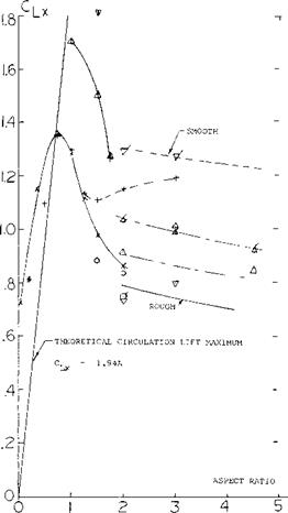
Equation 30 gives the maximum lift that could be expected by flow circulation. For very low A’ratio wings the actual C LX exceeds that of equation 30 because of the secondary lift term. This is illustrated on figures 6 and 22 for a rectangular wing with A = 0.2 where C LX is .95 compared to the expected maximum value from equation 30 of.388. Near C the secondary lift term caused by the flow normal to the wing was larger than the circulation lift term and results in a CLx ~ .562.

The maximum lift and stalling characteristics of low aspect ration wings vary widely as shown on figures 5, 6 and 8. Since the stalling process is due to separation and is influenced by the secondary lift of the wing, theoretical solutions are lacking.

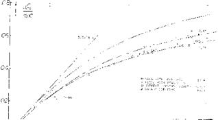
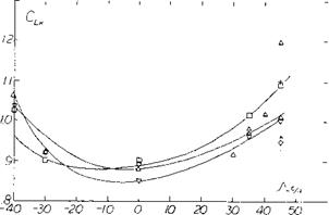
Variation of С^л With Aspect Ratio. In figure 23 the CLx is given as a function of aspect ratio from the test data of (17). In the range of A – 3 comparison of the data with that presented in Chapter IV indicates that to estimate CLX in this range the more extensive empirical data given in the chapter on stalling should be used. Below an aspect ratio of 2 C Lx appears to increase with decreasing A’ratio until the theoretical maximum is obtained and then starts to decrease. The data on figure 23 again illustrates further examples of C exceeding the theoretical maximum In the lower aspect ratio range A 1, C LX appears to be nearly insensitive to the section configuration, although the tip configuration appears to be important. Wings with rounded tip tend to have higher values of CLX than square tip wings.

MAXIMUM LIFT

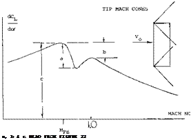
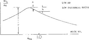
a, b and c CORRESPOND TO dCL/dcY AS IN FIGURE 2 0-

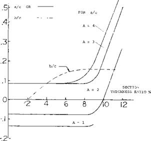
Figure 22. Data for estimating critical points of lift curve slope in transonic range.

At A above 1.5 there is a large variation of CLX

which depends on cross section, taper ratio and hading edge sweep angle. Tip shape also appears as an important parameter influencing C|_x • The condition of the leading edge and, therefore, Reynolds number effects CLX, the change being similar to that noted in Chapter IV where airfoils tested in the smooth condition show a AClx 0.3 to 0.4 above the value tested in the rough condition. Except for those points noted the data given in figure 22 should be assumed to correspond to the rough leading edge condition.

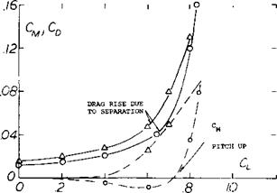
Type of Stall. The test data given on figures 5, 6 and 8 show that the stall can either be very sudden or rounded. At A ^ 3 the type of stall appears to depend

on the leading edge radius as discussed previously. When the wing has an A’ratio below 2 the shape of the leading edge has little influence and both sharp and well rounded types of stall are observed. It does appear that when the C^_x exceeds that expected based on the two dimensional section, the stall will be very sharp. This is illustrated for the wings using Clark Y sections.

FLAT PLATE

II

o’

II

<

1.0

RN.45 to 1.8(10)6

(17,h)

NACA 6ЗАО04

A = 0, Л =

1.0

RN=1.25 – 1.70(10)6

NACA 6ЗАО06

-A = 0 > =

1.0

63A010

JV =16.7 to

7.6,

A= .5 3(10)6

(17, g)

63A010

A = 35° to

45°

(17, g)

NACA 0012

LE = ROUGH

(17,f)

NACA 0012

LE = SMOOTH

CLARK Y

SQUARE TIPS

(17,i)

CLARK Y

ROUND TIPS

(11, b)

CLARK Y

ROUND TIPS

(11,b)

FLAT PLATE IN WATER, FIGURE 6.

MAXIMUM LIFT

Figure 23. Maximum lift of small aspect ratio wings including theorectical maximum for circulation lift.

COMPRESSIBILITY

Low aspect ratio wings are used for high speed aircraft because of the delay of the drag rise and improved performance at Mach number above 1.0. The change in the Mach number for the drag rise and the drag at high speed of low aspect ratio wing is given in the book “Fluid Dynamic Drag”.

LIFT AT M < 1. Compressibility encountered at higher subsonic speeds affects the sectional lift angle, that is, in large-aspect-ratio wings, see Chapter VII. For slender wings (say, below A = 1) the formulation (l, i) predicts that compressibility does not have any influence upon the linear, circulation-type lift component. According to the Prandtl-Glauert rule, any wing reacts as though its chord would be lengthened in proportion to the Prandtl factor

“P” = 1/ ^1 -Мг = l/p (25)

This means that the effective area is increased and the aspect ratio decreased. According to Equation 5, the lift-curve slope is not affected by these variations.

In aspect ratios above A == 1, there is a transition between the two extreme ranges considered above. It may be instructive, however, to use equation 23 with a modified Prandtl function reducing the sectional angle of attack for low lift coefficients

dcz /dCL = (10 + 8/A2 ) (1 – М2)П + 20/A (26)

Подпись:COMPRESSIBILITYПодпись:The exponent varies between zero at A well below unity, and n = 0.5 for higher aspect ratios. We have evaluated available experimental results (16). After excluding various points which simply cannot be right, the most likely function of n is as in figure 19.

Non-Linear Lift. The effects of compressibility on the non-linear component of lift is not described by any available theory. If the increase is due to drag based on the flow normal to the wing it would be expected that the component would not change at Mach numbers below 1. Нс ‘ >ег, if the component also depends on the cross sectional area and this is effectively increase by compressibility, the non-linear component 1 should in­crease with Mach number. Thus the к determined from figure 7 would be modified for compressibility by the equation

к = P £Cl /sin2o’ (27)

where P = 1/(1 – Mz )n and n is the Prandtl-Glauert factor modified by A’ratio given on figure 19. More study and experimental data is required to confirm equation 27.

ASPECT RATIO A [131] [132]

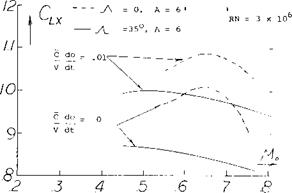
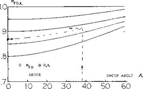
Подпись:Transonic Range. Above the critical Mach number the lift curve slope of low aspect ratio wings is reduced by the formation of shock waves on the upper surface. These shock waves effect the lift in the same manner as for a two dimensional wing, Chapter VII. The result of this is a sharp reduction of lift after the critical is reached with a recovery at approximately M = 1, as illustrated on figure 20. The Mach number at which the lift slope break occurs is a function of the aspect ratio and the angle of sweep.

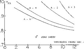
For straight wings this Mach number can be estimated using figure 21. The minimum lift slope will be obtained at

MLm =d+MLBf (28)

(17) Low aspect ratio wing tests including CL x:

(a) Nelson, Wings on Transonic Bump, NACA IN 3501.

(b) Nelson, 38 Cambered Wings, NACA TN 3502 (1955).

(c) Nelson, 36 Symmentrical on Bump, NACA TN 3529.

(d) Nelson, 65-210 Wings with A = 1 to 6, NACA RM A 9K18.

(e) Allen, Plan-Form Body Taper Effects and Mach No. Effects A = 2, 3 and 4, NACA A53C19.

(f) Jones, Low Speed Tests Rectangular Planform A = 1, 2 and 3 Wings, NACA RM L52G18.

(g) Dods, Test of Nine Related Horizontal Tails A = 2 to 6, NACA TN 3497.

(h) Graham, Large Triangular Wings, NACA RM A50A04a.

(i) Zimmerman, Clark Y Airfoils of Small A’ratic. NACA TR 431.

COMPRESSIBILITY

Figure 20. Typical variation of lift curve slope in the transonic range with associated shock waves.

COMPRESSIBILITY

COMPRESSIBILITY

Figure 21. Charts for calculating force break Mach number of straight and swept wings.

SUPERSONIC RANGE. At Mach numbers above those where the shock waves are attached to the wing, theory (16,a) provides a good insight into the performace of wings. At low lift coefficients the linearized theory gives for the lift curve slope the equation

dCL _ rr / 1

^ AS Jut – 1 2kjuz – Г*29)

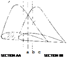
This applies to rectangular wings where the center port ion of the wing is operating in two dimensional flow and the tips are within the Mach cone as illustrated in figure 23.

It is expected that as in the subsonic range a non-linear component of lift will be generated that will add to that of equation 29.

CHARACTERISTIC DATA

Some of the detailed test data on low aspect ratio wings confirm the concepts discussed in the previous section. However, because of the many variables involved it is difficult to determine that portion of the non-linear lift curve, yaw effects, maximum lift and compressibility effects of low aspect ratio wings. Thus, some of the available experimental data relating to these problems are presented in addition to the data given on figure 5.

Circular Planform. Disks and circular “wings” are an extreme of round planform. Available experimental data are plotted in figure 8. Sharp-edged plates have a linear lift-curve slope as high as indicated by the upper line in figure 3. The Clark-Y profiled wings (ll, b) are at least in the forward 50% of their lateral edges rounded; and their lift is reduced accordingly, to the lower limit as in figure 3, at A = 4/rr = 1.27. If the cross section shape is viewed based on drag it appears the wings with the flat tops should have the highest lift. This is generally true as noted in figure 8.

Ellipsoid. When increasing the thickness ratio of a disc, we may arrive at bodies similar to those in body (A) of figure 8. Such shapes have been wind-tunnel tested in (11 ,c, d,e) with stabilizing flaps and fins attached, for possible use as re-entry vehicles (from outer space). To us, the ellipsoid in the graph, is the perfect example for the life-reducing effect of rounded trailing and lateral edges of any wing. As a matter of interest, the maximum (L/D) ratio of the shape shown is 10, at CL = 0.2. Effectiveness can greatly be improved by horizontal tail flaps (11 ,d, c) which are necessary anyhow to stabilize and to control the body when really used as a vehicle.

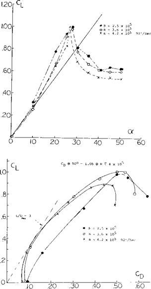
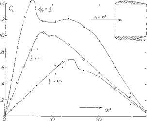
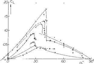
The Discus. Disregarding any dreams of “flying saucers”, the athletic implement called discus seems to be the only practical application of a circular planform. The ballistics and aerodynamics of the discus have been investigated by Ganslen (12,b). Figure 9 presents the aerodynamic forces. The lift shows clearly an initial linear slope and a non-linear movement. Stalling takes place at of =29 . The normal force resumes growing above

40 ° , reading at 90 the drag coefficient C D =1.06. The pitching moment (not reported) is certainly “up”. The longest distances, some 60 meters, throwing a discus are obtained when launching at some 35 (against the horizontal) but at an angle of attack (against air) slightly below zero. The rotation imparted when properly throwing (some 6 revolutions per second) stabilized the discus, thus minimizing the pitchup (against the hori­zontal). The ballistic trajectory necessarily ends, however, at an angle of attack above 35 , that is in stalled

condition. At least part of its way, the discus is, nevertheless, gliding at an (L/d) ratio reaching a maximum of 3, at = 10 (against the air).

CHARACTERISTIC DATA

DISCUS CROSS SECTION

CHARACTERISTIC DATA

Figure 9. Lift and drag characteristics of discus.

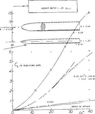
Streamline Body. The flat body as in figure 10 may be a streamline body. As such it should be discussed in the chapter on this subject. However, we can also claim this body to be a low-aspect-ratio wing with rounded lateral edges. Doing so, it must be noted that there is a straight and blunt trailing edge. The non-linear component is only ( ACj_ /sin2- of ) = 0.15, for A = 0.16. As seen in figure 10, this is the lowest point near A = zero.

The well-rounded shape in combination with a high Reynolds number is evidently responsible for this result. The flow simply gets around the lateral edges. By comparison, a sharp-edged flat plate having approximately the same aspect ratio exhibits twice as much non-linear lift as the round body. The linear lift component is also low for the flat body, around Vi the theoretical value as in figure 3. It is suggested that the blunt (and sharp) trailing edge of the body prevents this component from being still lower.

CHARACTERISTIC DATA

Figure 10. Lift and drag characteristics of a flat streamline body (10,b).

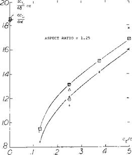
Tests of flaps on rectangular wings with A = 1.25 from (13,a) figure 12 show that below a flap to wing chord ratio Cf / C = .25 the lift slope is not linear. This tends to confirm the data of figure 11 and also shows the importance of the trail edge shape or angle on flap effectiveness.

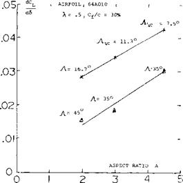
The characteristics of flaps as a function of aspect ratio is given on figure 13. For the 30% chord flaps tested in (13,b) the effectiveness is reduced with both A’ratio and sweep angle. With a reduction of A’ratio below 2 it is expected that 30% flaps will be even less effective than the trend illustrated on figure 13.

Horizontal Tail Surfaces. Low and moderate aspect ratio wings are used as horizontal tail surfaces. Available experimental results for such surfaces are given on figure 14. In some applications gaps are found for the rudder and the planform is rounded. The use of a correction factor a of.85 for the surfaces without gaps and.75 with gaps results in good correlation of the experimental data. Further discussions of the character­istics of tail surfaces are given in Chapter IX.

CHARACTERISTIC DATA

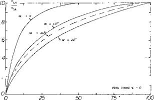
Figure 11. Ratio of CL c, lift to a given chord station to the total lift coefficient C L j, for a rectangular wing of A = .25.

Подпись:Flap Characteristics. As previously noted the area of a small A’ratio wing aft of its maximum effective width does not produce lift. This occurs as explained in (l, i) because the down wash produced by the sections in front of the maximum effective width will operate in a flow field equal to the angle of attack of the section. Thus, the flow becomes parallel to these sections. The ratio of the lift to the total, CLC / CLT, as measured in (5,c) is given on figure 11 as a function of chord length. For the flat plate rectangular wing, operating at = 10° , 95% of the lift is generated on 60% of the wing chord. Thus, the effectiveness of the area where flaps would be used is reduced and we would expect that flap effectiveness would also be less.

L

asr

6


CHARACTERISTIC DATA

AIRFOIL SECTIONS TESTED


c

c

c


d


CHARACTERISTIC DATA

Figure 12. Flap effectiveness as a function of flap chord ratio for a rectangular wing with A’ratio = 1.25.


CHARACTERISTIC DATA

Figure 13. Hap effectiveness on low A’ratio wings with and without sweep.


CHARACTERISTIC DATA

/ t i _ A =E/s

] 1 2 3 4 5

Figure 14. The lift-curve slope of horizontal tail surfaces tested alone (without fuselage) as a function of their aspect ratio.


CHARACTERISTIC DATACHARACTERISTIC DATA

Aspect Ratio. Referred to the area S = d c CL = 7Y(d/c) sinot ; dCL /dot = (24)

( rr2/180)(d/c) = 0.055 (d/c)

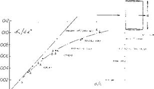
CHARACTERISTIC DATAExperimental results in figure 17 confirm the equation (24) very well. Regarding the airfoils as in figure 17, the effective diameter is questionable in connection with the highly cambered Clark Y foil section. We have assumed a d/c = 0.1 to account for some of the airfoil thickness corresponding alternate points are included in figure 17. Agreement with the “sharp” rectangular wings in figure 3 is obtained at small aspect ratios, when referring C l. to the area (2 d c). This result means physically that the volume of air affected (deflected) by the ring wing corresponds to a stream cylinder with a cross-section area two times that of the opening area of the ring.

Figure 16. Lift of a series of ring wings (14,e).


CHARACTERISTIC DATA

О _____ L_____________ ■_____________ .____________ *

0/234


Figure 17. Lift-curve slope of ring-shaped wings as a function of their aspect ratio (14).


CHARACTERISTIC DATA

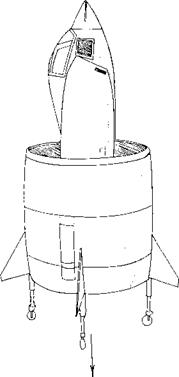
Figure 15. Jet-powered French VTOL aircraft SNECMA “Coleopter”, as shown on the cover of Newsweek 5 Oct. 1959.

(14) Characteristics of small aspect ratio ring wings:

(a) Weissinger, Ring-Wing Theory; Rpts 2,39,42 (1955/57) of DFL; and ZFW 1956 p 141; also USAF OSR TN 1958-224.

(b) Richter, Ring Aerodynamics, Yearbk WGL 1955.

(c) Fletcher, 5 Annular Foils, NACA TN 4117 (1957).

(d) As developed in France, see Seibold, Ring Plus Machinery, Yearbk WGL 1954 p 116.

(e) Weissinger, Ring Plus Body, AFOSR TN 60-343 (1960).

CHARACTERISTIC DATA

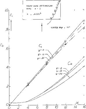
Figure 18. Lift and drag characteristics of a low aspect ratio wing operating at yaw angles.

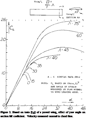
EFFECTS OF YA W. The influence of the wing tip on the characteristic of low aspect ratio wings operating in yaw can be large. For instance, a rectangular wing with an aspect ratio of one becomes a double delta or diamond shaped wing with the one tip becoming the leading edge. Thus, if the wing were operating at a yaw angle of 45° the tip shape would have the same influence as the original leading edge. When operating at a yaw angle the vortices at the tip become influenced by the tip sweep angle.

(15) Effect of yaw on low aspect ratio wingsi

(a) Schock, Low A’ratio Wings with Sharp Leading Edges, Princeton Aero Eng Report No. 574.

(16) Compressibility effects:

(a) Ferri, Elements of Aerodynamics of Supersonic Flows, Macmillan Co. 1949.

Smoke surveys (15,a) on a rectangular wing of A = 2 indicated that position of the tip vortices are influenced by the yaw angle as well as the angle of attack. Typical results are given on figure 18. Note that with increasing lift the vortices move inward from the tip but the movement is less as yaw angle is increased. The upstream vortex height decreases with angle of attack, while the vortex from the downstream decreases in height. From figure 18 it will be noted that both the lift and drag decrease with increasing yaw angle. If the effective aspect ratio or span is considered it would be expected that the lift would increase with yaw angle as indicated by equation 7.

NON-LINEAR LIFT COMPONENT

The lift curve slope of low A’ratio wings increases with angle of attack over the basic slope determined from equations 10 and 12 on figure 3. This non-linear increase of the lift curve slope is a function of the wing aspect ratio, its lateral edges and the component of velocity normal to the wing. The lift component above the circulation lift has been the subject of many investigations (4) and is a function of the flow about the lateral edges of the wing. In some ways it appears that the non-linear component of lift is caused by the drag based on the normal velocity component. Although the vortices at the lateral edges are on the upper surface of the wing they appear to be stable, thus giving some doubt to the drag concept where the Karman vortex street might be expected.

(6) Lifting characteristics of tapered wings:

(a) Anderson, 22 Tapered Wings, NACA T Rpt 572 & 627 (1936/38); also Analysis in Rpt 665 (1939).

(b) Whicker, Control Fins, TMB Rpt 933 (1958).

(c) Wolhart, With A = 2 to 6, NACA TN 3649 (1956).

(d) Allen, 3 Taper Ratios on Fuselage, NACA RM A1953C19.

(e) King, Taper-Ratio Seris, NACA TN 3867 (1956).

(7) It has been observed on a circular cylinder that the vortex street ceases to exist below a certain angle of attack.

(8) (a) Anderson, Systematic Investigation of 22 Tapered Wings, NACA T Reports 572, 627, 665. (b) Larger aspect ratios, NACA TR 669.

Larger A’ratios, NACA T Rpts 669 & 824, ARC RM 1708.

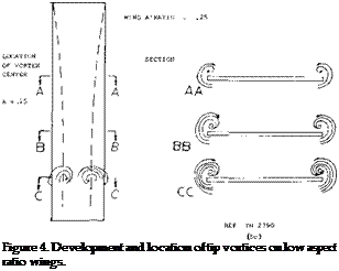
Подпись: (8,b) (8,a) (8, a,b) (5,b) (3,c) (8, c) (3,b) (3,d) (3, f) (5,a) Basic Flow. The flow pattern of slender wings can best be understood by considering the extreme case of A —>- 0. Physically, this condition can be produced by placing a long strip of material in a wind stream, at a longitudinal angle of attack. Since there is ‘‘no” leading or trailing edge, there cannot be any circulation as explained in Chapter II. Lift is still produced, however, by downward deflection of, and by imparting momentum onto a certain cross section or “slot” of, the air flow, This is accomplished by a pair of vortex sheets curling around the lateral edges, as shown in figure 4. This type of flow was observed from test of a flat plate with an aspect ratio of.25 (5,c) where tuft studies and flow measurements were taken. As shown in the illustration, the streamlines are spreading outboard on the lower side of such wings. The flow separates from the upper side and a strong vortex forms along each edge. It cannot be said, however, that all of the flow is separated. The inboard sides of the vortices impinge upon the wing, and they are the mechanism through which some fluid is transported from the lower to the upper surface. Eventually, the flow leaves the trailing edge in a manner similar to that of any conventional wing. We may consider the vortex system to be fully rolled up, however, essentially consisting of a pair of contracirculating vorcices.

Cross Flow. The manner in which the non-linear component of lift of slender wings is often explained is by stating it is equal to the force developed in the lift direction by drag, based on the velocity normal to the wing. If the component of velocity normal to the wing is V sin a then the force normal to the wing is

N = Co0.5? (V0 sinoif (13)

as explained in Chapter XV and in the book “Fluid Dynamic Drag”. Resolving N in the lift direction

^Ncosa; = Cp 0.5 ^ (V0 sin of)2- cosex’ (14)

where лЬ(у| is equal to the non-linear component of the lift. If the corresponding part of the total lift coefficient is лСрп then

АС|__П = Cq sin2c* cos o( (15)

Since there is some doubt that the non-linear component of lift is the same as that represented by the drag coefficient in normal flow we will substitute the factor k’ forCp in the above equation, thus:

ACLn – k’ sintf cos o’ (16)

The question on the use of CD in equation 15 is because of the apparent lack of a vortex street (7). Such a street can be understood to be produced by separation with alternately forming vortices. It is possible that the main component of flow V cos of tends to stabilize the vortices so that they form continuously and are carried away down stream. Thus, the vortices do not build up in size and separate as with a flat plate normal to the wing. When suppressing the lateral motion (by a “splitter” plate placed in its plane of symmetry) ordinary more or less symmentric and steady separation takes place. As shown in Chapter III of “Fluid Dynamic Drag”, the coefficient is then reduced to Cp =1.6. The magnitude of the factor k’ in equation 16 is thus doubtful, if really identifying it with drag.

Theory. Many attempts have been made to find a solution for the seemingly simple flow pattern of slender wings (4). For A = 0, which means the case of a very long straight strip of material exposed to a flow at a certain angle of attack, the lift function is

ACl = k’ sin or cosof (17)

For the wing with. A = 0 the potential lift slope, dCu /dof is zero at ex’ =0, figure 5. Thus the total lift coefficient of the zero A wing is that of equation 17. According to (4 a) k’ = 2. The close agreement with the drag coefficient in two dimensional flow in this case is only coincidental however.

+ NACA, t/c = 12% IN 2-DIM1L TUNNEL 0 NACA, TAPERED, A = 6 and =12

* NACA AND ARC, 0012, A = 6 Д NACA, CLARK Y, VARIOUS A1RATIOS О AVA, SHARP-EDGED RECTANG WINGS Г BRUNSWICK, A = 3 INVESTIGATION A ARC, RECTANGULAR, A = 0.5 and 2

* SCHOLZ, RECTANGULAR, A = 0.5 О NACA, RECTANGULAR PLATE

* WINTER, STRIP WITH A = 1/30

NON-LINEAR LIFT COMPONENT

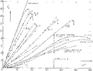
Figure 5. Lift coefficient of profiled, sharp-edged rectangular (and of some other) wings, as a function of angle of attack (adjusted for zero lift where necessary) for various aspect ratios.

NON-LINEAR LIFT COMPONENT

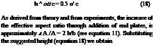
Подпись: h ^ oti c = 0.5 o' c (18) As derived from theory and from experiments, the increase of the effective aspect ratio through addition of end plates, is approximately А А /А = 2 h/b (see equation 11). Substituting the suggested height (equation 18) we obtain
NON-LINEAR LIFT COMPONENT

£A ^ 2A<Xi c/b = 2 or – (19)

Consequently, for wings with A < 1, and 2 o(L = of , the increment in effective aspect ratio is found to be ДА ^ o’ . The effective aspect ratio AL = A + A A of such wings, therefore, increases with the angle of attack; and the lift increases at a rate higher than linear (9,c). Combining equations 5 and 19, replacing <X by the more correct term of sinof, and after introducing cosof (to indicate the difference between the vertical lift and the inclined normal force), the lift coefficient of wings with aspect ratios below unity may tentatively be

Cu = 0.5 ТГ sine* cosof (A + of ) (20)

NON-LINEAR LIFT COMPONENT

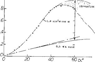
Figure 6. Lift characteristics of a thin flat plate having an The “second” component of lift in this equation is aspect ratio of A = 0.2, tested fully submerged in a

towing tank (3,f). = 0.5 Tf sin2- oc cosof ^ 0.5 V o’ (21)

Two Components of Lift. Wings never have a ratio A = zero. There are always edges which can be considered either to be trailing (thus causing some circulation) or leading (permitting some circulating flow to get around). A number of experimental lift functions are plotted in figure 5 for aspect ratios between 0. and 12. It is generally assumed that the lift of such wings is made up of two components, a linear one (due to circulation) equations 5 and 6, and a non-linear or quadratic term (due to the lateral-edge vortex flow). As an example, experi­mental results of a plate having an A’ratio of 0.2 are presented in figure 6. After subtracting a linear compon­ent found by equation 5, it is found that equation 17 agrees well with the experimental points when using k’ = 1.8.

End Plate Effect. According to (9,a) a vortex sheet (rather than a “round” vortex) originates along each of the lateral edges. These sheets combine with the sheet coming from the trailing edge so that a U-shaped vortex wake is formed. One can then say that the long-chord wing leaves behind a vortex pattern very similar to that of a (short-chord) wing fitted with end plates. In rectangular wings, the height ЧТ of the imaginary end plates is assumed to be equal to the vertical distance between vortex core and trading edge. At A’ratios below unity, this height corresponds to oq = 0.5 or ; hence:

This time, the factor к is almost = 1.6. The end-plate formulation gives a qualitative explanation for the existence of two different components of lift in aspect ratios below unity. However, quantitative questions such as to the shape of wing planform and lateral edges remain unanswered.

NON-LINEAR LIFT COMPONENT

Figure 7. Second, non-linear component of lift, of plates and profiled lifting devices (wings) as a function of their aspect ratio.

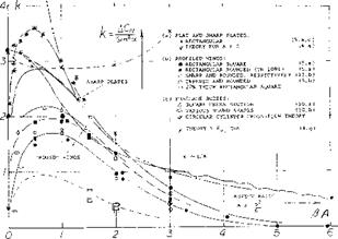
Подпись:Подпись: aNon-Linear Component. Using equations 10 and 12 or the functions plotted in Figure 3, the linear circulation-type lift, potential flow lift, can be determined from experimental results such as in figure 5, for example. The non-linear “second” lift component of wings can thus be isolated from total values of lift or normal force. Such statistical data are plotted in figure 7 in the form of

(Л C(_ /sin2 or) or (aCn /sin2 or ) (22)

This type of evaluation is somewhat uncertain insofar as the value of the linear component depends upon planform and lateral-edge shape of each wing tested. There cannot be much doubt, however, about the following conclusions:

(a) The value of ‘к’ to be used in equations 16 and 17 in order to obtain the second component of lift varies between zero and a maximum of 3.6.

(b) Sharp-edged plates show the highest values of kk’. They seem to meet the theoretical value of 2 as in (3,a) at A = 0.

(c) Wings with rounded lateral edges show ‘k’ factors which are considerably reduced, together with the effective span of such wings.

(d) Lift-producing efficiency is also affected by “round” planform. Wings with full-span and straight trailing edges are, on the other hand, most efficient as to the magnitude of the non-linea:: lift component.

Leading-Edge-Suction. Using an extension of the leading-edge suction analogy presented in (5,a, a) of chapter XVIII a theoretical method of finding the characteristics of low A wings with various planforms has been developed. This theoretical approach (4,g) finds the potential flow and non-linear lift terms for various wing planforms. For rectangular planform wings the theoretical potential flow lift agrees closely with that given on figure

5. The lift due to the vortices developed on the top wing surface as shown in figure 4 are given in terms of к as a function of A on figure 7. In the low aspect ratio range from A = 0.3 to 1.5 the theoretical leading-edge-suction analogy method appears to agree with the statistical data. This is especially true considering that the theory applies for wings with sharp edges.

FRONT ELEVATION SIDE ELEVATION

NON-LINEAR LIFT COMPONENT

Figure 8. Characteristics of small aspect ratio wings with circular planforms and dihedral. Clark-Y Sections.

In the absence of any solution really indicating the magnitude of the second lift term, the statistical results in figure 7 will permit to estimate that component in practical applications. Regarding the magnitude of k’ around A = 0.5, it is suspected that theories advanced so far (6) are not based upon the right mechanism. It is suggested that each lateral vortex not only produces lift by itself, but that it also increases the circulation over the rest of the wing area. Any end-plate effect (as in equation 18) may thus lead to the exponential increase as in figure 7, between A = 6 and 1. On the other hand, at A—0, there is no circulation which could be increased. According to these speculations, we end up with two non-linear components of lift; and it might not be a coincidence that k’ = 2 (as per equation 17) plus 1.6 (as per equation 21) equals 3.6 (as seen to be the maximum in figure 7).

(9) End-plate principle and non-linear lift:

(a) Mangier, in Yearbook D Lufo 1939 p 1-139.

(b) Expansion of the principle in (l, f).

(c) The principle is but a way of explaining that the volume (mass) of air onto which a downward momentum is imparted by the wing increases in proportion to the angle of attack and to the chord. That the principle is not perfect becomes apparent when considering drag due to lift of such small-A’ratio wings; see “Fluid Dynamic Drag”. The solution as in (4,f) assumes not only “end plates”, but a complete “box” of streamlines.

(10) Lift characteristics of streamline bodies:

(a) AVA Gottingen, Fuselages, Ergebnisse II (1923); see also Muttray in Lufo 1928/29 p 37.

(b) Bates, Various Fuselage Bodies, NACA TN 3429 (1949).

(c) NASA D-l 374.

(11) (a) AVA Gottingen, Flat Disk, Ergebnisse IV (1932).

(b) Zimmerman, 3 Clark-Y Wings, NACA TN 5 39 (1935).

(c) Mugler, Lenticular Shape, NASA TM X-423 (1960).

(d) Ware, Stability and Control, NASA TM X-431 (1960).

(e) Demele, With Fins and Flaps, TN D-788 and TM X-566.

CHARACTERISTICS OF SMALL ASPECT RATIO WINGS

The flow around the tips of a low aspect ratio wing has a greater influence on the operating characteristics than for wings with A = 5 and above. Thus for low aspect ratio wings, the procedures and data given in Chapters MI and XV do not apply. In this chapter low aspect ratio wings with rectangular, tapered and round planforms will be considered. Included will be wings with swept leading and trailing edges. Those classes of wings with delta type planforms will be considered in the next chapter. Small or low aspect ratio wings are defined as those with A < 3. Between A = 3 and 4 the aspect ratio is defined as the intermediate type.

The lift curve slope of low aspect ratio wings increases with angle of attack up to the stall angle rather than remaining linear as in the case of conventional wings. The increase in slope is a secondary effect that takes place over and above the basic circulation lift slope. In the treatment of low A’wings, first the basic slope character­istics will be covered and then the secondary non linear effects.

FLOW MECHANISM. The lifting-line theory given in Chapter III represents very well wings with aspect ratios above A = 5. In the case of a wing having a chord which is long in comparison to, or let’s say longer than the span, wings with small aspect ratios, the trailing edge of the wing is exposed to a flow which has been deflected by the leading edge. In this manner the airfoil sections of any finite-span wing are placed within a field of streamlines which are curved in proportion to the permanent deflection (downwash) produced by their own lift. In other words, the chord and curvature are large so that the ratio of the chord in the radius of the stream curvature is also large. As a consequence, the airfoil sections lose lift, their sectional lift-curve slope is less than in two – dimensional flow and the lift angle of the average section is increased. Of course, the induced angle is also increased corresponding to C [_ /А as in larger aspect ratios.

Подпись: (i)Подпись: = 2 Тґ ka

1. BASIC LIFT CURVE SLOPE

When considering the theory for determining the per­formance of small aspect ratio wings the conventional lifting line concept can no longer be used because of the long chord to span ratio. Thus, the lift cannot be assumed to act on a line and must be spread out over the surface of the airfoil. Also, the influence of the lateral edges (a minor effect in larger aspect ratios) becomes more and more predominant as the aspect ratio approaches zero. As in the “straight wing” chapter, small aspect ratios rectangular lifting surfaces with sharp lateral edges are found to be very effective.

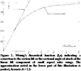
Lifting Surface. Several attempts (1) have been made to extend the lifting-line theory into the range of small aspect ratios or to replace it by so-called lifting – surface theory which accounts for the effect of the wing chord upon the lifting characteristics. One such theory is presented as follows: According to (l, a) the sections of rectangular low-A’ratio wings are aerodynamically in the same position as those in a two-dimensional cascade of airfoils. This analogy amounts to replacing the wing surface by a large number of lifting lines. Disregarding those near the leading edge, an individual airfoil or vane in that cascade develops less lift per unit of angle of attack than in free flow (that is, less than one airfoil alone) because of the downwash already produced by the other vanes located ahead. The average two-dimensional lift – curve slope is reduced accordingly to:

dCL /doL,

where the subscript 42’ indicates the two-dimensional sectional angle of attack required and the correction factor к is

к = (A/2a)tanh(2a/a) (2)

as plotted in figure 1.

SLENDER WINGS. Below A = 1 the factor as in figure 1 is simply

к = 0.5 A/a = 0.5 “A” (3)

The resulting sectional “lift angle” in this range from equations 1 and 3 is

do(z /dCL = 1/ (rr A) (4)

This is also equal to the induced lift angle as in Chapter

III. The geometric angle required is the combination of the induced and two-dimensional angle, and is

da /dCL = 2/rr(A) or dCL/da = 0.5ТГ A (5)

in radians

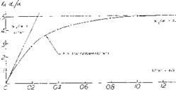
As shown in figure 2, the equations 4 and 5 indicate that below А я* 1 with к = 0.5 “A”, da^ /da = 0.5

and/or (X = 2 & і. The physical meaning of this result is that the final downwash angle £ = 2 occ is reached before the trailing edge of such wings. Cutting off some piece from this edge does not, therefore, reduce the lift for a given span (considering only small values of the lift coefficient). This conclusion can be formulated by referring the lift coefficient to the “span area” b, rather
than to the conventional wing area. For CLb = L/q b^ we thus obtain dCLb //da = rr/2 = constant, which shows that the linear lift of such wings (with A between 0 and a maximum of 1, and at “small” lift coefficients) is independent of their chord. This fact is also the reason that the factor ‘a’, the slope of the lift curve, no longer apears in equation (5). If there are any viscous (boundary-layer) losses, there are many airfoils farther downstream in the cascade which can make up for those losses.

Another theoretical treatment (l, i) of low aspect ratio wings takes into account the flow about the lateral edges. This is done by considering the flow of the airfoil of the low aspect ratio wing as two dimensional when viewed in cross section perpendicular to the longitudinal axis. This flow superposed on the original stream leads to the same result as given in equation 5. The analysis was done by first considering pointed v/ings and showing that no lift is developed downstream of the section with the longest span. This is a necessary condition to satisfy the Kutta condition. Thus only the flow ahead of the section influences the lift at any station and not the flow downstream as in high aspect ratio wing theory. This concept also leads to the equation for the induced drag coefficient

CDl = o’ /2 in radians (6)

Подпись: Figure 1. Weinig’s theoretical function (l,a) indicating a correction to the section lift or the sectional angle of attack of the linear lift component of small aspect ratio wings. The approximation noted in the lower part of this illustration is perfect, down to A = 1.5.

(1) Small-aspect-ratio linear wing theory:

(a) Weining, Small Span, Lufo 1936, 405; NACA TM 1151.

(b) Weissinger, Yearbk D Lufo 1940 p 1-145; ZWB Rpt FB 1553 (1942), see NACA TM 1553; Tech Berichte ZWB 1943; ZWB Rpt UM 1392 (1944); Math Nachrichten 1949 p 46; ZFW 1956 p 225; see NACA TM Г120 and TN 3476.

(c) Falkner, ARC RM 1910 (1943) and 2596 (1948).

(d) Jones, Correction for Chord, NACA TN 817 (1941).

(e) Lawrence, Journal Aeron Sciences 1951 p 683.

(0 Kuchemann, Straight & Swept, ARC RM 2935 (1956).

(g) Pistolesi, 3/4 Chord Principle, Conf Lil’thal Ges Lufo 1937 p 214; applied by Weissinger (l, b).

(h) Taylor, Lifting Surface, ARC RM 3051 (1957).

(i) Jones, Properties of Low-Aspect-Ratio Pointed Wings, NACA TR 835.

CHARACTERISTICS OF SMALL ASPECT RATIO WINGS

Figure 2. Ratio of induced angle of attack to geometric value, based on equations 4 and 5.


Plan form

Lateral

Edges

Ab/b

(1+ Ab/b)’

Rectangular

Sharp

zero

1.00

Elliptical

Sharp

-0.04

0.92

Rectangular

Round

-0.09

0.83

Rounded

Round

-0.12

0.78

Delta wing

Round

-0.12

0.78


Lift-Curve Slope. Writing the angle in degrees equation (5) reads:

A value of (1 + лЬ/Ъ) ~ (1 + 2 Д b/b) ^ 0.8 has been used in figure 3 to obtain the lift-curve slope of “round” wings from experimental data below A = 1.

dCL /dtf° = TT[130]A/360 = 0.0274 A. (7)

This function is well confirmed in figure 3 by experi­mental results on thin rectangular plates. The presented points have carefully been determined as tangents of the lift-curve slopes in the vicinity of C L = 0. In some cases (not plotted) these tangents are not readily available; the theory then serves to understand such experimental data. Up to about A = 2.5 lifting characteristics of sharp-edged rectangular wings can be approximated in form cf their lift angle

dc* /dCL = (36.5/A) + 2 A @ A 2.5 (8)

HIGHER ASPECT RATIOS. The hyperbolic tangent as in equation (2) is tabulated in mathematical or engi­neering handbooks. Up to an argument “x” = 6 , or = 0.1, tan“x” = sin“x”. The hyperbolic tanh function reaches unity at “x” = 360°, or more precisely at “x” = °o. As the factor к varies between (0.5 “A”) at A below unity, and 1.0 at A oo the angle ratio ( oq/oe ) varies between 0.5 and (2/“A”). Within the range between A ^ 1, and = 5 or 10, a transition takes place from the low A’ratio to the lifting-line function. Using a = 0.9, and the induced angle (20/A), we can use for sharp-edged rectangular wings the same equation as in Chapter III:

dtf" /dC, = 10 + (8/A2 ) + (20/A) (10)

Experimental points, plotted in figure 3, in the form of the lift-curve slope, confirm this function very well.

Effective Span. We have explained in Chapter III how rounded lateral edges and “round” planforms reduce the effective aspect ratio of wings. In the range of low A’ratios, this influence takes on the character of A; /А = constant, for a given shape of the edges and/or the planform. Assuming that the effective span of a rectan­gular wing be reduced by дЬ/Ь, the effective area is reduced to Se/S = (1 + Ab/b) and the effective aspect ratio Al IA also to (1 + л b/b), where Ah has a negative valve. Keeping the lift coefficient based upon the original area, we then find that the lift-curve slope of wings with aspect ratios below unity is reduced in propor­tion to (1 + Ab/b), thus:

dCL/dc/ =(1+д b/bf 0.0274 A (9)


08r


r


dcL

d«°


CHARACTERISTICS OF SMALL ASPECT RATIO WINGS

tf-r

CHARACTERISTICS OF SMALL ASPECT RATIO WINGS


/


.06-


THEORY (4.q)


.04-


к


NOTE :


Thus based on equation 8, half of the reduction is due to area and the other half due to aspect rati:». The experimental points in figure 3 indicate span reductions as follows:


*•/


a-E/s


/


5 6


CODE TO FIGURE 3


CHARACTERISTICS OF SMALL ASPECT RATIO WINGS

CHARACTERISTICS OF SMALL ASPECT RATIO WINGS

Подпись:x SHARP RECTANGULAR PLATES ■PROFILED RECTANG, SQUARE ENDS & PROFILED DELTA WINGS V0012 DELTA WINGS, BRUNSWICK DPROFILED RECTANG, ROUNDED EDGES О ROUNDED AND ROUND WINGS WTAPERED WINGS, SQUARE ENDS – TAPERED AND ROUNDED • SHARP ELLIPTICAL PLATES AVA + RECTANGULAR W’ROUND EDGES A RECTANGULAR PLATES D-1374

Figure 3. Linear lift-curve slope (at samll lift coefficients) of wings (and plates) as a function of their aspect ratio.

Round Tip Wings. We have found that Ab values for round and rounded tip wings are constant in the form of ( лЬ/Ь) for small A’ratios, equation 8 and in the form of (дЬ/с) for larger aspect ratios. In between these extremes there must be a transition. Mathematically this transition can be accomplished by putting

Подпись:Подпись: Figure 4. Development and location of tip vortices on low aspect ratio wings. ( ab/c). = ( Able) / VT+2/а" (11)

where (.) indicates the value as in small A’ratios. Note that at A—0, there will be ( Ab/b) = ( дЬ/с)/ V 2 = constant. — We have empirically found that n = 3 is suitable; and that above A = 2, constant values ( дЬ/с) can be used, as for example those listed in various illustrations in Chapter III, without further correction. As in that chapter, the lift angle of typical round tip type wings, is

doc /dCL = 10 + (10/A2 ) + (26/A) (12)

as plotted in figure 3. A “corection” to lifting-line theory, for round planforms, is proposed in (l, d). Using again a = 0.9, this formulation gives results between those for the sharp-rectangular and the “round” wings as in figure 3. We prefer equations 10 and 12, giving us a distinction between two extreme shapes of otherwise straight wings.

(4) Theoretical Analysis non-linear lift small A’ratios:

(a) Bollay, At Zero Aspect Ratio, Zts Ang Ma:h Mech 1939 p 21; also in J Aeron Sci 1936/37 p 294.

(b) Empirical, see NACA TN 2044 & 3430, T Memo 1151.

(c) Theoretical considerations (J Aeron Sci 195 3 p 430, 1954 p 134 & 690) indicate a term Ci_~ Such a trend may account for the type of increase as in figure 7 between A = 0 and 0.5.

(d) Attempts at analyzing mechanism and lift due to the lateral-edge vortices of delta wings are also found in J Aeron Sci 1954 p 212 & 649; see also Weissinger, ZFW 1956 p 225 and Mangier, R Soc London Proc Ser A 1959 p 200.

(e) Brown, Delta Wings, NACA TN 3430 (1955).

(f) Gersten, Non-Linear Theory, ZFW 1957 p 276 and Ybk WGL 1958 p 25.

(g) Lamar Leading-Edge-Suction Analogy around side edges NASA TR R-428.

(5) Experimental investigation of rectangular wings:

(a) Winter, Plates and Wings of Short Span, Forschung 1935 p 40 & 67; Translation NACA T Memo 798.

(b) Zimmerman, Clark-Y Airfoils, NACA T Rpt 431 (1932); see also J Aeron Sci 1935 p 156.

(c) Wadlin, Hydrodynamic Rectangular Plates, NACA TN 2790, TN 3079 & 3249 or T Rpt 1246 (1955).

(d) AVA Gottingen, Ergebnisse I & III (1921/27).

(e) Scholz, Forschung Ing’Wesen 1949/50 p 85.

(f) Bartlett, Edge Shape, J Aeron Sci 1955 p 517

(g) Weinstein, Planing Plate, NACA TN 2981 (195 3).

(h) Brebner, Series of Wings, RAE (1965); AD-48 0253.

(i) Campbell, Small A’Ratios, ARC RM 3142 (I960).

DEEP STALL

The advent of the swept wing transport aircraft with aft “T-TAILS” and aft mounted nacelles has led to a number of fatalities that stem from the aircraft entering a region known as “deep stall”. The first major accident from deep stall occurred during a test flight of a twin engine swept wing T-TAIL airplane while determining its stall character­istics.

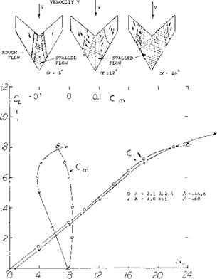
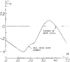
Basic Cause. The basic cause of deep stall is the unstable pitching moment generated by the wing when operating at high lift coefficients, (18). This moment tends to drive the airplane to high angles of attack unless corrective action is undertaken. Since swept wing aircraft stall at very high angles of attack, it is possible for the airplane to be at a very high angle. In this condition the separated flow from the wing and nacelles, (18,a), blanket the horizontal tail with low energy air making it an ineffective control, as illustrated on figure 36. The separated wing flow reduces the maximum available nose-down pitching moment, fig­ure 37, so that once the airplane exceeds a angle of attack of 40° the airplane is locked in a deep stall condition. When in this condition the drag is very high, due to the separated flow, making it impossible to add enough thrust to fly the airplane out of this condition. Lateral controls are also ineffective due to stalling at the wing tips.

Deep Stall Prevention. Since an airplane can always enter a stall in the event of bad weather or other emergencies, the design must be changed to eliminate the problems discussed above.

There are several ways in which this can be accomplished and these have been discussed in previous sections of this chapter. Basically, the wing and wing flap systems must be designed to eliminate nacelles which leads to the use of T-TAILS, the strategic location of wing fences can be used with moderately swept wings, such as the early DC-9s. These fences induce a vortex over the horizontal tail which energizes the flow and maintains effective controls (18,f). Other methods of eliminating the blanketing of the horizontal tail is by the strategic location of the nacelles with respect to the fuselage.

Since the down wash produced by the center section of the wing can impinge on a high T-TAIL at the deep stall condition, some aircraft have been designed with a low horizontal tail of conventional types which remains effec­tive at high angles of attack. Thus, effectiveness is ob­tained because the lower tail operates in air that is not affected by the wing wake. The low tail requires that the engines be placed elsewhere on the aircraft, which can also lead to other problems..

DEEP STALL

REFERENCE LINE HORIZON

RELATIVE WIND

FLIGHT PATH

LOW ENERGY WAKES OF WING AND NACELLES

DEEP STALL

DEEP STALL

Figure 37. Typical variation of pitching moment before and after deep stall condition.

Mechanical Warning Devices. Since the stalling of swept wing aircraft can lead to extremely dangerous conditions, many mechanical devices have been investigated to warn the pilot of impending stall. These devices include both stick shakers and stick pushers. The stick shaker is ar­ranged so that as stall is approaching the pilot is given warning by artificial shaking. With smaller aircraft, buf­feting usually provides the necessary warning by shaking the stick, but with heavier aircraft with more advanced control systems, an artificial means is required. Another means of preventing the pilot from entering a stall is to effectively take the airplane out of his hands with a “stick pusher”. Such a device is used on several T-Tail swept wing transport aircraft as discussed in (18,e). There are, of course, many pros and cons with regard to the stick pusher configuration, but it has been selected as an effec­tive safety device as the deep stall condition is such a disasterous maneuver.

Figure 36. Aircraft entering deep stall condition.

(18) Deep Stall:

a) Polhamus, Deep-Stall of T-Tail Aircraft Space and Aero­nautics May 1966

b) Powers, Deep-Stall Pitch-Up T-Tail Aircraft NASA TN D-3370

c) Thomas, Longitudinal Behaviour Near-Stall AGARD Proc. No. 17

d) Taylor, Stability of T-Tail Transports, J. Aircraft July 1966

e) Davies, Deep Stalling, Flight International 18 March 1965

f) Shevell, Design Features of the DC-9, J. Aircraft. Nov. 1966.

HIGH LIFT DEVICES FOR SWEPT WINGS

Подпись: EFFECT OF ASPECT RATIO
HIGH LIFT DEVICES FOR SWEPT WINGS
Подпись: (15) Leading Edge Slats: a) Hunton, Slats and Flaps on a Swept Wing, Section Charac-teristics, NACA TN 3040. b) Naeseth, Double Slotted Flaps with a Leading Edge Slat A = 35° , NASA D103. c) Adcock, Leading Edge Slots to Aircraft With Swept Wings, Vol. 1, Boundary Layer & Flow Control, Pergemon Press 1961. d) Olason, Design Philosophy Boeing 737 J of A, Nov-Dec 1966

The use of swept wings on transport aircraft has led to the development and application of highly sophisticated de­vices to increase the lift and reduce the adverse pitching moment at the takeoff and landing conditions. With the first generation of swept wing jet airplanes the devices to increase lift were relatively simple. The need to increase the payload while maintaining the same airport restric­tions resulted in the use of more advanced high lift de­vices. The STOL transport with field length requirements of 3,000 feet or less force the use of even more advanced devices for increasing lift of swept wing aircraft.

HIGH LIFT DEVICES FOR SWEPT WINGS

WING LOADING. The need for high lift devices on swept wing is apparent when the wing loading is examined. Fighter airplanes typical of World War II could be pulled out of a dive (at well below the speed of sound) with 10 “g’s” (if needed) without stalling. Their wing loading was in the order of 40 lb/ft2(below 200 kg/m2). By compari­son, a modern transport airplane may have wing loadings of 100 lb/ftг (more than 400 kg/n/). For the same landing speed, the airliner should thus have a maximum lift coefficient, 100/40 = 2.5, or at least two times as high as that of the assumed fighter. This means tha: CLX should be in the neighborhood of 2.7 to 3. When operat­ing at these high lifts the induced drag coefficient may then be four times as high, and the total D/L at CLX possibly three times as high. This means roughly a sinking speed also three times as high as that during the landing approach of the fighter some 20 years earlier.

DESIGN FOR HIGH CLX. Due to the high wing loading the design of auxiliary devices for high lift on swept wing requires consideration of the drag and pitching moments characteristics as well as the overall complication of the mechanism. Because the flap and slat systems become more complex as the requirement for CLX is increased it becomes a major design problem to develop the simplest and most effective total system. This is apparent when one observes the wing during the takeoff and landing conditions when it appears to come apart in all directions as a result of deploying the various high lift flaps and slats. The choice and location of the high lift devices is depend­ent on the geometry of the wing which is determined based on the high speed cruising requirements.

HIGH LIFT DEVICES FOR SWEPT WINGSTo determine the best configuration of the multi-element airfoils, the lift requirements are established spanwise on the wing so that at each station two dimensional data can be applied. The data on the high lift characteristics of leading and trailing edge devices are given in Chapters V and VI. The combination of slats, leading and trailing edge flaps for a swept wing should be selected so that the stall first occurs inboard to provide a stable moment curve, a negative – pitching moment, through the stall. The high lift devices should also be selected so that the drag is compati­ble with the engine thrust during take off and emergency landing conditions.

Подпись:

(16) Leading Edge Flaps:

a) Griner, Lateral and Longitudinal Stability A = 47.7 , A = 6, NACA RM L53G09.

(17) Trailing Edge Flaps:

a) Naeseth, Double Slotted Flaps – Swept Wing Transport, NASA TN D103.

b) Capone, Longitudinal Characteristics Subsonic Transport, NASA TN D5971.

In addition to developing a wing with high lift and good pitching moment characteristics it is necessary to maintain minimum drag so that peak take off and landing perform­ance can be obtained. This is necessary as the drag must be compatible with the engine thrust, especially during emergency conditions. To determine the best performance that can be obtained the lift drag ratio of the wing is found based on the drag coefficient from the equation

CD =CD0 +CL2/efTA (9)

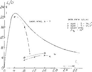
Where e is the span efficiency and C Do is the drag coefficient at zero lift. Thus, for any wing the ideal or best lift drag ratio can be established as a function of CL. The actual performance can then be compared to the ideal to determine where improvements are needed.

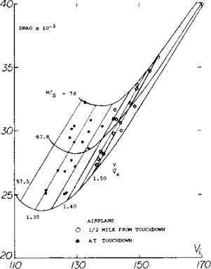
On figure 30 the ideal lift drag ratio for A = 7 compared with test data (17,a) of various combinations of flaps and leading edge devices. From such a study the best combina­tions of high lift devices can be found for the wing at any lift coefficient.

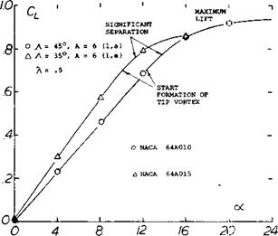
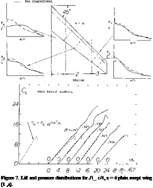
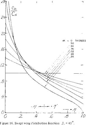
Because of the boundary layer transport as influencing maximum lift, especially inboard, high lift devices must be very effective, especially with those used outboard. For instance as was shown on figure 7, the sectional lift coefficient is twice as high as the corrected two dimen­sional at the.383 station for a swept wing with A = 45° and A = 6, while at the tip maximum lift coefficients are nearly equal. Thus, to obtain the required characteristics of C L and Cn large increases in CLX are needed for the outboard sections if the entire wing is stalled a: the same angle.

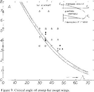
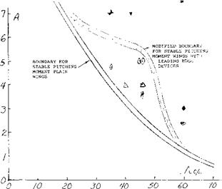
In (9,a) it was shown that leading edge devices covering as much as the outer 75% of a 35° swept wing would provide sufficient protection from stall to obtain a stable pitching moment. With – Л = 45° only one combination tested gave the required stable pitching moment while at A = 60 the moment remained unstable.

HIGH LIFT DEVICES FOR SWEPT WINGS

Figure 30. Maximum lift drag ratio for wings of a fixed aspect ratio in comparison with actual wings with high lift devices.

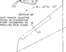
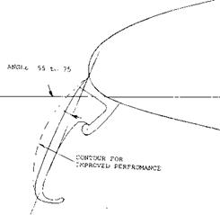
LEADING EDGE SLAT. The slat, figure 1, Chapter V, is used on many swept wing airplanes to prevent stall on the leading edge. Generally, the slats cover approximately 50% of the span and are installed in segments so their angle can be varied to get the desired stall protection. The slats increase CLX of the airfoil with or without trailing edge flaps. The design and performance improvement of the slat as used on two dimensional sections is covered in Chapter VI. In the application of slats to a swept back wing to prevent the unstable pitch up moment while obtaining maximum lift, it is necessary to use as large a surface as possible (15,c). The tip chord of the slat should be as large as practical with 30% of the wing chord being considered a maximum. The slat should extend inboard as far as possible without causing the unfavorable pitch up moment as stall approaches. The slat should also be ex­tended as far outboard as possible. However, it is not necessary to extend it outboard of the point shown on figure 31. The ends of the slats are generally cut off on a plane normal to the quarter chord point, also shown on

figure 31. Further details on the design of slats are given in Chapter VI, including load and moment data. In the selection of the slat maximum operating angle it is neces­sary to use a deflection that will cover the stagnation point. This requires a much larger angle than is normally covered in the literature, especially for wings with very high values of CLX.

10-20°/eU-

HIGH LIFT DEVICES FOR SWEPT WINGS

Figure 31. Slat geometry as installed on a swept wing to protect tip stall (15,c).

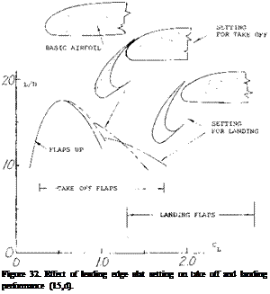
Подпись:The choice of the slat position is a function of the position of the trailing edge flaps and is determined by the lift drag ratio of the system (15,d). Shown on figure 32 is the lift drag ratio as a function of operating CL for the slats retracted at take off position and at landing for a typical transport airplane. The triple slotted trailing edge flaps are at the best angle for peak performance. It should be noted that with the flap set for the take off the slat is operating at approximately 45° with no slot, or in the sealed position. This is done to achieve peak performance, maximum L/D and ^LX •

is desirable at takeoff and landing. These levels transform into CLx for the complete swept wing of 2.9 to 3.1. The details of the design of trailing edge flaps are given in Chapter V and include concepts of blowing to further increase maximum lift.

In the application of trailing edge flaps to swept wings the spanwise coverage is set up to provide as much area as possible within the constriction of nacelles and lateral control devices. After the type of flap has been chosen the deployment angles must be established for the takeoff and landing conditions. These angles are established based on the lift drag ratio (15,d) as illustrated on figure 32. Note that the trail edge flap angle is linked to the leading edge slat to control its angle. Since the lift drag ratio controls the takeoff and climb performance, the level of drag developed by the high lift devices is as important as


HIGH LIFT DEVICES FOR SWEPT WINGS

Figure 33. Leading edge flap geometry.


HIGH LIFT DEVICES FOR SWEPT WINGS

LEADING EDGE FLAPS. The leading edge flap is also used to prevent separation on the wing and increase CLX. The device known as a Kruger flap may either swing out from the lower surface of the wing or may be part of the wing leading edge, sliding out as illustrated in figure 25 of Chapter VI. The performance improvement gained with the use of leading edge flaps is similar to that measured with slats (15) and is achieved by the effective increase of camber at the wing leading edge. The maximum lift and its corresponding angle of a swept wing is influenced by the length of the flap, its deflection angle and leading edge radius. Although the leading edge flap is generally flat, as shown in figure 33, improvements have been found with the use of curvature as is used on the 747 airplane. The performance characteristics of Kruger flaps can be esti­mated using the data of figure 26 Chapter VI.

As tested on a 47.5° swept (13,1) leading edge flaps have little effect on the CLX when operating without trailing edge flap, the improvement in CL = .07 maximum for the best combination of angle and area, figure 34. The largest improvement in performance is the lift drag ratio at CLX which is important from take off and landing consider­ation. Although the increment of maximum lift due to the deployment of leading edge flaps is small when operating on a clean wing, large improvements in C^x can be expected when it is operating in conjunction with trailing edge devices as shown in Chapter VI.

TRAILING EDGE FLAPS. The maximum lift of swept wings with leading slats and flaps is determined by the type and effective area of the trailing edge flap. Most sweep wing transport aircraft use either a double or triple slotted flap system which achieves levels of CLy in two dimensional flow of approximately 3.3 or better while maintaining relatively low levels of angle of attack, which


HIGH LIFT DEVICES FOR SWEPT WINGS

LE f


HIGH LIFT DEVICES FOR SWEPT WINGS

Figure 34. Effect of leading edge flaps on the maximum lift coefficient of swept wings.


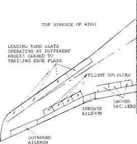
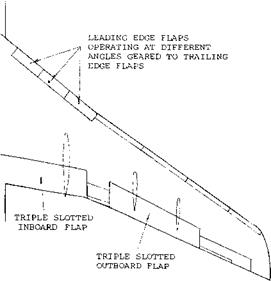
TYPICAL HIGH LIFT DEVICES – SWEPT WINGS. As indicated in the previous sections swept wings are de­signed using a series of leading edge slats, leading edge flaps and trailing edge devices. An example of how these are installed on a typical swept wing transport airplane is shown on figure 35. It will be noted that leading edge slats cover approximately 60% of the wing span and these are located outboard. The angle of the leading edge slats varies as a function of the percent deployment of the flap system. This is done to maintain the minimum drag neces­sary for best takeoff, climb, descent and landing perform­ances. The leading edge slats are arranged in four segments with the maximum deployment angle on the outboard sections. This effectively gives the maximum lift increase outboard where it is needed. Leading edge flaps, which swing out from the under surface of the wing, are em­ployed inboard to increase maximum lift during the final stage of the landing. The Kruger flaps are used on the inboard sections of the wing because of the large leading edge radius of the thicker sections of the wing.


HIGH LIFT DEVICES FOR SWEPT WINGS

HIGH LIFT DEVICES FOR SWEPT WINGS

HIGH LIFT DEVICES FOR SWEPT WINGS

BOTTOM SURFACE OF WING

HIGH LIFT DEVICES FOR SWEPT WINGS


Figure 35. Typical transport aircraft wing configuration including slat and flap locations.

As shown on figure 35, the wing incorporates triple slotted flaps located inboard and outboard. Between the flaps an inboard aileron for lateral control, and on the outboard section another aileron is used. The triple slotted flaps operate at angles varying from 5° to 40° depending on the flight mode. The highest flap angle is useful just before touchdown. Also employed on the wings are flight and ground spoilers. The flight spoilers are used to increase the drag during descent to limit air speed and are located just about the outboard flaps. The ground spoilers, located above the inboard trailing edge flap, are used to kill the lift on touchdown to provide improved braking forces.

The wing described is typical for that found on aircraft introduced in the 1960’s. Later transport aircraft use even more complicated devices, as the maximum aft during both take off and landing is extremely important with regard to the economics of swept wing aircraft. For in­stance, the Kruger flap is curved during its deployment as shown on figure 33. With the introduction of STOL aircraft the devices will become even more complicated find extensive and will incorporate all the concepts dis­cussed in Chapters V and VI.

COMPRESSIBILITY EFFECTS

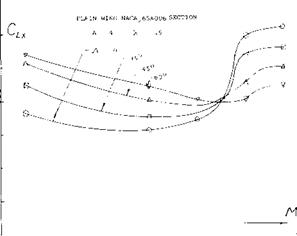
As the operating Mach number increases and exceeds the critical, the influence of compressibility becomes of major importance in the design and operation of swept wings. In addition to having a large influence on the drag, the effects of compressibility effect the usable operating CL prior to buffet, maximum lift, the longitudinal pitching moment and stability. The variation of the maximum lift coefficient with Mach number on figure 25 illustrates compressibility effects for a range of sweep angles of plain wings with an aspect ratio of 4. The effects of compressi­bility are also influenced by the nose radius, taper ratio, aspect ratio and load distribution. These parameters in­fluence the location of shock waves and the corresponding areas of separation as a function of operating Mach num­ber (14,e).

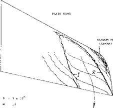
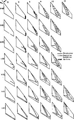
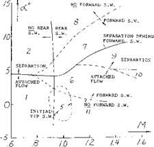
Flow at high Mach number. To illustrate the flow associ­ated with swept wings at high Mach numbers as a function of the operating condition, the variation of the location of the vortices and the various shock waves formed on the wing are shown on figure 26. In the Mach number range below.85 it will be noted that with increasing angle of attack vortices are formed on the lead edge of the wing and tend to move inboard, leaving the tip stalled with separated flow at the high angles. At a Mach number of.95 a standing shock wave is first formed near the tip of the wing due to the local velocity exceeding M = ]. At this Mach number, the standing shock moves inboard with increasing angle of attack and again the leading edge vortex is formed. It behaves in the same manner as the vortex at the lower Mach numbers. At even higher Mach numbers in the neighborhood of 1.4, the standing shock wave is first formed near the trailing edge of the wing at zero angle of attack. With increasing angles a shock is formed toward the lead edge of the wing. The lead edge vortex is formed aft this shock. With further increases in angle of attack the tip of the wing becomes highly ineffec­tive, especially at the higher Mach numbers. The highly complex flow pattern discussed above from (14,a) is typi­cal and influences the conditions where buffet takes place. The various regions of flow for a 53.5° swept wing of A = 2.8 and Л = .333 are given on figure 27.

BUFFETING. As a result of the shock waves and vortex flow separation, buffeting is encountered on swept wings in the transonic flow region. This unsteady flow limits the operating CL to a so-called buffet limit. The limiting CL is influenced by the aerodynamic parameters of the wing, sweep angle, section type, taper ratio, aspect ratio and load distribution. Light buffet generally coincides with the drag divergent Mach number where the first shock wave is formed. The critical pitch up lift coefficient is generally at CL’s higher than those for the buffet bound­ary. This means that the pilot may be warned by struc­tural vibrations prior to pitch up. As noted in (14,b) there are four different regions of the wing that must be consid­ered for buffet effects:

1) The upper leading edge

2) The tip region

3) Downstream area influenced by leading edge vorticity

4) The trailing edge location.

These regions are identified on figure 27 as a function of angle of attack and Mach number. As a result of the combined effects in the above region of vortex formation and bursting along with the intersection of shock waves the CL for buffet, CL B, can be severely reduced, espe­cially with wings where Л>50°.

COMPRESSIBILITY EFFECTS

О_________ і_______ і________ і_______ і________ і________ і_______ і_______ і_______ і——– 1——- 1——- 1—

0 .2 F.6 S /-0 /-2

Figure 25. Maximum lift characteristics of plain aspect ratio for swept wings as influenced by compressibility (14,e).

The results of tests conducted to M = .93 indicated that for wings in the sweep range of 25 to 45° and aspect ratio 4 to 6 the highest buffet lift coefficient is obtained with the wing with the best aerodynamic efficiency This is illustrated in figure 28.

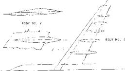
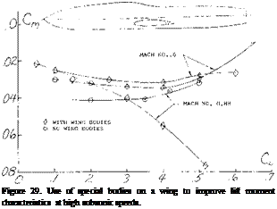
When operating at transonic Mach numbers with swept wings of high aspect ratio the separation and associated buffet can be delayed to a higher speed with the addition of bodies on the upper surface of the wing (14,f). These bodies cause an actual reduction of drag as well as an improvement of the pitching moment characteristics of the configuration, figure 29. The bodies reduce the separa­tion by eliminating the extensive cross flow in a manner similar to fences. Such bodies have been used on commer­cial transport aircraft with a reported improvement in cniising speed.

COMPRESSIBILITY EFFECTS

Figure 26. Variation of lead edge vortex separation shock waves and separated boundaries as a function of Mach number. Aspect Ratio = 2.8, Sweep Angle = 53.5 .

NUMBERS INDICATE REGIONS OF:

(1) ATTACHED FLOW, NO SHOCK WAVES.

(2) SEPARATION AT THE LEADING EDGE FORMING A VORTEX.

(3) FORWARD SHOCK WAVE ONLY, NO SEPARATION.

(4) FORWARD SHOCK WAVE ONLY, SEPARATION AT THE SHOCK FORMING A VORTEX.

(5) INITIAL TIP SHOCK WAVE, WITH OR WITHOUT A REAR SHOCK.

(6) FORWARD AND REAR SHOCK WAVES PRESENT, NO SEPARATION.

(7) FORWARD AND REAR SHOCK WAVES PRESENT, SEPARATION BEHIND THE FORWARD SHOCK FORMING A VORTEX.

(8) REAR SHOCK WAVE ONLY, LEADING-EDGE SEPARATION FORMING A VORTEX.

(9) FORWARD AND REAR SHOCK WAVES INTERSECTING ON THE WING WITH A STRONG OUTBOARD SHOCK WAVE CAUSING SEPARATION.

(10) FORWARD AND REAR SHOCK WAVES INTERSECTING AT THE TRAILING EDGE.

(11) REAR SHOCK WAVE ONLY, NO SEPARATION.

COMPRESSIBILITY EFFECTS

Figure 27. Regions in which shock and/or separation occur on a complete wing. Aspect Ratio = 2.8, Sweep Angle = 53.5 .

SWEPT WING MODIFICATIONS FOR STALL

From the previous discussion of the characteristics of simple swept wings operating at high angles of attack, it is apparent that changes are needed to prevent tip stall and the positive pitching moment prior to and after the devel­opment of. The modification should not lead to an increase in drag near stall nor should decrease the lift drag ratio of the design condition or spoil the other desirable qualities of the wing.

SWEPT WING MODIFICATIONS FOR STALLModifications to improve stall and pitching moment are needed for swept wings operating at the take off and landing condition and at high speeds. At take off and landing the effects of flaps, slats and other leading edge devices must be considered. During high speed operation the drag of such devices is high so only clean wings with low drag characterises are used.

TWIST AND CAMBER MODIFICATION. In the case of straight tapered wings it was shown in Chapter IV that the undesirable tip stalling could be eliminated by changing the load distribution on the wing. This change was made with tapered wings by reducing the angle of attack at the tip, “wash out”. A similar change could have been made to make the wing stall inboard by increasing the section camber or the wing chord on the outboard stations, in the case of straight wings a relatively simple change in load distribution will correct the tip stalling problem.

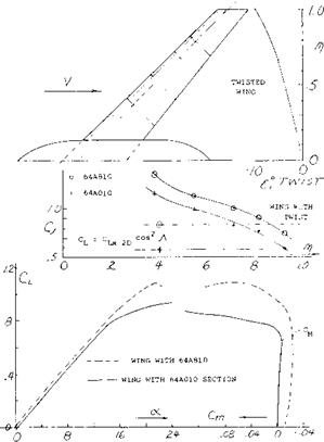
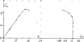
With swept wings, especially those with high aspect ratio and sweep angle, such corrections in load distribution do not necessarily eliminate tip stalling and the correspond­ing positive pitching moment. For instance in the case of a 45° swept aspect ratio 6 wing with а Л = .5, an increase of camber to CL^ = .8 and 10 degrees of wash out did not eliminate tip stalling (10,a). As shown on figure 17, this highly modified wing still has the undesirable positive pitching moment at stall.

The large increase in CLX on the inboard stations due to the boundary layer flow makes it extremely difficult to correct tip stalling with the application of twist and cam­ber. As noted on figure Clx is 50% above the value based on section data at the.545 wing station. At the tip stations however, the CLX is nearly equal to the value expected from section data. To make the wing stall in­board first, large changes in the spanwise distribution

SWEPT WING MODIFICATIONS FOR STALL

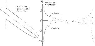
Figure 17. Camber and washout changes to improve usable operat­ing lift coefficient (l, a).

SWEPT WING MODIFICATIONS FOR STALL

SWEPT WING MODIFICATIONS FOR STALL

Figure 18. Lift and pitching moment characteristics of a 35° swept wing designed for constant Ck = .8 without auxiliary devices (10,e).

angle or camber are required and the changes necessary will increase with aspect ratio and sweep angle. The large increase in camber and angle outboard will be undesirable from drag consideration, thus it may be desirable to increase the taper and so reduce the tip chord to obtain the desired loading.

A design study and experimental program (10,e) to inves­tigate the performance of a wing with a constant spanwise pressure near C^x was conducted to determine if the local stall could be made to occur inboard. The wing investigated had a sweep angle,-A. = 35°, A = 7.04 and t/c = 10%. The twist and camber distribution used to obtain a constant CL near maximum lift is shown on figure 18. It should be noted that the wing has an extensive twist and camber change from root to tip, including the use of negative camber inboard.

The tests did indicate that the operating CL was constant across the span near the stall angle taking into account Reynolds number and local flow problems at the wing root. The test data, figure 18, however, indicated that as the wing stalls a strong pitch up moment is encountered. Although the pitch up moment would be expected for a similar simple swept wing, the modification of camber, chord and twist should have been sufficient to give the desired negative pitching moment. The boundary layer flow and detailed vortex distribution of the swept wing must change the detailed section pressure distribution to develop the positive pitching moment. Since large varia­tions of twist, camber and chord appear to only partially improve the characteristics of a swept wing, other devices must be employed to achieve the desired results.

BOUNDARY LAYER FENCES. In the earliest days of propeller-driven airplanes the engine nacelles usually in mid-wing position (and in the slipstreams) may have pre­vented any spanwise boundary layer transport. In single­engine airplanes and in all modern configurations where the jet engines are mounted, whether below the wing or behind the wing at the sides of the fuselage, the boundary layer transport described previously can be reduced by fences (thin plates) placed on the upper wing surface. The fences may be used across the entire wing chord or may cover only the leading or trailing edges. The use of wing fences is to effectively dam the boundary layer air and to direct it back on the wing in the direction of flow so that the effect of the inboard section is not felt by the out­board section.

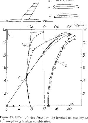
The use of fences for control of the boundary layer on wings has been investigated for many different combina­tions of sweep and aspect ratio. For instance, on a wing with 40° sweep and A = 7 (11,a) full chord streamwise fences were tested along with various other configura­tions. In general the usable operating CL was increased before an unstable moment was encountered, but even with the largest number of fences the pitch up moment was not eliminated, figure 19. The fences tended to in­crease the wing L/D at the higher lift coefficients but as might be expected reduced the L/D at low CL. A reduc­tion in size and number appeared to reduce the usable operating CL (ll, c). The lack of success of fences for eliminating the adverse pitching moment can be attributed to their localized action. For instance, consider the varia­tion of spanwise loading and section maximum lift coeffi­cient as illustrated in figure 15. The section CLX decreases toward the tip because of the spanwise flow of boundary layer. With the addition of a fence, as shown, tho action of the spanwise flow is decreased locally with the result that locally the value of ClY is equal to the two dimen­sional value. However the boundary layer action again develops outboard of the fence in this case, it has little effect on the overall value of CLX for the wing. For this reason, except in a few specialized cases, the use of fences will have limited success.

(11) Effect of Wing Fences on Swept Wings:

a) Dickson, Swept Airplanes With Fences, NACA RM A55C30a.

b) Sutton, Sweptback Wing with Four-Digit Sections to M = 0.92, NACA RM A54L08.

c) Bray, Fences on Longitudinal Stability, NACA RM A53F23.

d) Sutton, Fuselage-Tail Combinations – A – = 40, 45, 50, NACA RM A57F06a.

e) Hieser, Swept Wing with Nacelles, NACA TN 1709

SWEPT WING MODIFICATIONS FOR STALL

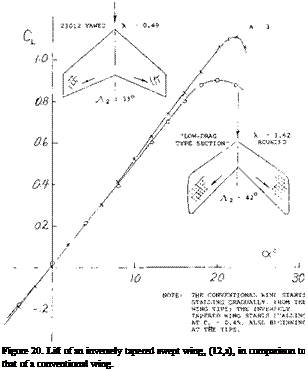
INVERSE TAPER. A radical attempt at preventing wing – tip stalling is shown in figure 20. The chord increasing toward the wing tips is expected to prevent stalling simply by reducing the lift coefficient near the tips. In compari­son to a conventional (tapered) wing comparable in aspect ratio and angle of sweep, it is seen that the lift curve slope is reduced. Assuming that the influence of the increased- length lateral edges may be cancelled by their rounded shape, we may conclude that the influence of lift distribu­tion (loaded near the wing tips) is responsible for an increased average induced lift angle. As a matter of fact, when extrapolating the functions in figure 9 of Chapter III into the field of taper ratios above unity, we obtain for Л = 1.6, a correction ДА in the order of —0.5. Notwith­standing the considerable differences in aspect ratio and the angle of sweep, a similar value is found when evalua­ting the experimental slope in figure 20 within the range of small lift coefficients. As to stalling, that begins at CL = 0.4 or 0.5 (as reported in (12,a) on the wing tips. This type of flow separation is also evident in the drag which increases rapidly to a level some 100% above that of the conventional swept wing, figure 8, Chapter XV. Note also, that the maximum lift coefficient (although for a differ­ent unidentified foil section) is appreciably reduced. In conclusion, increasing the chord outboard does not really help improve the characteristics of swept back wings.

(12) Taper Effects:

a) Purser, Various Sv/ept Shapes, NACA TN 2445.

b) Polhamus, Airplane Configuration Effects on Static Sta­bility, NACA RM L56A09a.

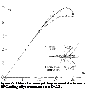
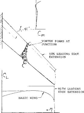
Подпись:A typical example of leading edge wing extension is shown on figure 22 for. A. = 45° and A = 6. As noted on figure 9, the wing would be expected to have a strong pitch up moment at high operating lift coefficients. By adding a 15% leading edge extension at the.55 semi span station, the pitch up moment was delayed to a CL = .95 as compared to.6 for the basic wing. The use of larger extensions spanwise appeared to improve the pitching moment characteristic; however, if too much of the wing is covered by a leading edge extension, (15,a) the inboard sections of the wing again become too effective with the result that the tip will stall first. The correct length of the leading edge extension must be selected for each combina­tion of sweep angle and aspect ratio.

In addition to improving the flow around the airfoil the leading edge extension will develop a vortex at its inboard end. This vortex, as shown in figure 23, is shed and flows chordwise effectively blocking the spanwise flow of the air in the boundary layer. This allows the outboard sec­tion to develop a higher C in relation to the inboard sections and improves the effectiveness of the leading edge extension. Tests (13) have been made of slots in the wing to duplicate this vortex with limited success in improving the CL where the pitching moment breaks in the stable direction.

(13) SWEPT WING MODIFICATIONS FOR STALLПодпись: Figure 22. Delay of adverse pitching moment due to use of 15% leading edge extensions set at E = 2.2 . Leading Edge Extensions Swept Wings:

a) Kelley, H. N., Low Speed Tests -A = 45°, A := 5, NACA RML55H19.

b) Good son and Few, Extension & Fence Tests, A = 45 , A = 4, NACA RML52K21.

c) Whitcomb & Norton, Extension, Notches & Droop A = 45°, NASA TN D834.

d) Sutton, Extensions for A = 40 , A = 7, NACA RM 55129.

e) Liner, Martz, Three Extensions, 55, 65 7 70%, A = 450 ? a = 5, NACA RM L53B02.

0 Lowry & Schneiter, Slots and Extensions & A Variations, A = 60°, NACA TN 1284.

g) Demele, Inverse Taper Leading Edge Flap, – A = 45 , NASA TN D138.

h) Weil & Morrison, Notches, Extension and Fences and Fences, Л = 45° , A = 4, NACA RM L5 3J27Ja.

i) Goodson, Leading Edge Chord Extensions, A = 4,-Л – = 40°, NACA RM L52118.

j) Spreeman, Chord Extensions, Flaps & Fences, M = .4 to.9, A = 4, A = 45° , NACA TN 3845.

k) West, Chord Extension, Fences, M = .4 to 1.03, A = 4,-Л – = 45°, NACA RM L53B02.

l) Furlong, A Summary Low Speed Longitudinal Charac­teristics – Swept Wing, NACA TR 1339.

m) TN 3040.

As a result of the use of slats and leading edge extensions the critical angle of sweep is improved as a function of aspect ratio, as illustrated on figure 24. Thus based on the available test data stable pitching moments can be ob­tained at higher angles of sweep or aspect ratios with the proper choice of leading edge devices. Two dimensional airfoil characteristics and the methods described previous­ly can be used to find the size of the extensions needed. In general, the size becomes critical with increasing sweep angles.

Сы

SWEPT WING MODIFICATIONS FOR STALL

Figure 23. Formation of vortex at leading edge extension junction blocking boundary layer (9,a).

(14) Compressibility Effects on Maximum Lift:

a) Hall, Swept Wing Flow Pattern, M = .6 to 1.6, ARC R&M 3271.

b) Mayers, Transonic Buffet 60 Swept Wing AIAA Paper 69-793.

c) Sutton, Buffet Investigation of an Airplane Configuration, NACARM A57F06a.

d) Ray, Buffet Characteristics Swept Wings, NASA TN D5805.

e) Turner, Lift, Drag and Pitching for Swept Wing in Tran­sonic Range, NACA Transonic Conference 1949.

f) Whitcomb, Bodies added on a wing for high speed. NACA TN 4293

SWEPT WING MODIFICATIONS FOR STALL

Figure 24. Critical angle of sweep as modified by leading edge devices.

CHARACTERISTICS AT HIGH ANGLES OF SIMPLE SWEPT WINGS

Typical characteristics of simple swept wings (1) with A = 35 and 45° as a function of angle of attack are given on figure 1. Although the change of lift as stall is approached and exceeded is generally gradual, the drag rise is very steep and the pitching moment curve becomes positive. These moment and drag characteristics tend to increase the wing angle of attack which is destabilizing and, of course, undesirable. Thus, modifications are required to eliminate or reduce the pitch up moment developed by swept wings. The stall characteristics discussed above are caused by the loss of lift at the wing tips which are located aft of the aerodynamic center. This lift loss causes a pitch up moment and is aggravated by a vortex formed on the leading edge of the wing that flows span wise inboard from the tip. With increasing angle of attack this vortex is shed further inboard from the tip causing an effective loss of aspect ratio with a sharp increase in drag as shown on figure 1. Thus it is also noted that at the stall angle the drag increases sharply reflecting the increase in separation and the decrease of effective aspect ratio.

(1) Stall characteristics of plain swept wings:

a) Hunton Section Characteristics A = 45°, A = 6, NACA TN 3008.

b) Goodman & Brewer. Low Speed, Aspect Ratio & Sweep Characteristics. NACA TN 1669.

c) Turner, Effects of Sweep on CLX, A = 4, NACA TN 3468

d) Platt and Brooks, Effects of A – 0, 35 and 45 at Transonic Speeds, NACA RM L54L31b

e) Hopkins, Effects of Sweep Forward and Back, A = -40 to +45°, A = 2.8 to 6.8, NACA TN 2284.

f) Kuhn and Wiggins, 45° Swept Wing at A = 2,4 & 6 with fuselage, NACA RM L52A29.

g) Pursen, Swept & Yawed Wings of Various Planforms, NACA TN 2445.

h) Haines, Tests of 50° Swept Wings, ARC R&M 3043.

Подпись: Gp — Cps cos .A.Подпись: Figure 2. Based on tests (l,g) of a yawed wing, effect of yaw angle on section lift coefficient. Velocity measured normal to chord line. Although the variation of the lift coefficient curve with angle is gradual after the stall is encountered, the usable value of lift coefficient is much lower than C, x because of the pitch up moment. This problem increases with speed as high speed buffet is encountered. Thus a rela­tively low useful value of lift are obtained at the higher operating Mach numbers. For these reasons when consid­ering swept wing aircraft the stall characteristics en­countered at both ends of the flight range are critical.

CHARACTERISTICS AT HIGH ANGLES OF SIMPLE SWEPT WINGS

CHARACTERISTICS AT HIGH ANGLES OF SIMPLE SWEPT WINGS

Figure 1. Typical characteristics of swept wing operating at high angles of attack.

MAXIMUM LIFT – SWEPT WINGS. As discussed in the last chapter the characteristics of airfoils installed on a swept wing, in accordance with the simple sweep theory, depend on the flow velocity normal to the effective wing chord line. The section ordinates normal to this chord line determine the pressure distribution on the airfoil. Figure 3 in Chapter XV shows that the pressure distribution on the airfoil is independent of the sweep angle, provided the velocity chosen is parallel to the chord line. Thus for a swept wing

(i)

where Cps is the pressure coefficient of a two dimensional section. Since the shape of the pressure distribution curve of an airfoil determines the maximum lift coefficient we can, therefore, expect that

cix =CLxs cos2-A. (2)

where C^Xs is the maximum lift coefficient of the sec­tion in two dimensional flow. Thus for a 45° swept wing, the maximum lift would be expected to be half that of an equivalent straight wing.

Tests (l, g) of a rectangular wing of A = 6 at yaw angles of 0 to 75° show, in figure 2 that C^xs actually increases with sweep or yaw angle rather than remaining constant as would be indicated by equation 2. At an equivalent sweep angle of 45° the level of CLXS shown is nearly twice that expected by equation 2.

Further experimental confirmation of the maximum lift characteristics of swept wings (1) tested as complete wings and on a reflection plane shows an increase of with A. These data, figure 3, show that both angle of sweep and aspect ratio are important in determining the level of maximum lift.

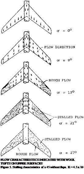
Подпись: c) LENGTH IF SEPARATION BUBBLE "ROM LEADING EDGE.Подпись:b) SECTION DRAG SHOWING SUDDEN INCREASE AT Cr. = 0.56.

FLOW UNSTABLE

CHARACTERISTICS AT HIGH ANGLES OF SIMPLE SWEPT WINGS

: 6.8 : 5.8 : 4.2

A = 6 (1, a )

NO TWIST NACA 64A006 TWIST NACA S.4A810 NACA 65A00C

Figure 3. Sweep angle and aspect ratio effects on CLx for simple swept wings.

WING TIP FLOW. In a manner similar to that of straight wings, a flow of air (including some boundary-layer mate­rial) around the lateral edge, is caused by the pressure difference between the lower and upper side of the wing. At the same time the boundary-layer material as in figure 4 moves along the upper side toward the wing tip. As illustrated in figure 4, the two streams meet and combine, thus forming a strong trailing vortex. It should be noted that at (A) there is a weak stagnation point (causing a small secondary vortex), while at (B) a pressure minimum is obtained, thus indicating location and path of the vortex as in figure 4. Another weak vortex is formed at C.

CHARACTERISTICS AT HIGH ANGLES OF SIMPLE SWEPT WINGS

With increasing angle of attack, the main vortex grows in diameter (if that word can be used) and it moves farther inboard, as far as one tip chord, for example, at cC = 15° for the wing as in figure 4. The lines (1) and (2) in the illustration roughly indicate the boundaries of the main vortex. Since the flow is a fully separated area at (3), the forward corner of the wing may just as well be cut off as shown.
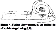
Подпись: Figure 4. Surface flow pattern at the stalled tip of a plain staged wing (l,h).

Подпись: BOUNDARY LAYER FLOW. The increase of CLX of swept wings above that expected by the simple sweep theory is caused by the flow of the boundary layer from root to tip, especially near the trailing edge of the wing. Thus the boundary layer flow acts in a manner similar to the use of suction for preventing separation, and allows the wing section to develop a higher lift coefficient than would be measured in two dimensional flow. The reason for the boundary layer flow is illustrated on figure 5 and is caused by the span and chordwise pressure distribution

A = 6 swept wing

Подпись:Подпись:on the wing. Consider for instance the pressure distribu­tion of sections AA and BB shown on figure 6. At point (a) on section AA it is noted that the negative pressure remains lower in the chordwise direction than spanwise until point (b) is reached. Thus, the flow will move along the chord as shown. However, when point (b) is reached the pressure is lower outboard at (c) on section BB than at (c!). This causes the flow to move in the spanwise direc­tion.

Since the spanwise flow of the boundary lave]’ prevents, separation on the inboard sections of the wing unstable flow first starts at the tip of the wing and is a function of the airfoil section type, leading edge radius and Reynolds number. This tip separation spreads to the leading edge at the tip and continues to move inboard with increasing angle of attack as shown on figure 5. With a further increase of angle the vortex separates from the leading edge inboard of the tip and flows chordwise. This leaves the tip of the wing completely stalled. The span station where the separation takes place continues to move in­board with increasing angle of attack.

CHARACTERISTICS AT HIGH ANGLES OF SIMPLE SWEPT WINGS

Figure 6. Section pressure distribution for swept back wings as influencing boundary layer flow.

The data (l, a) given in figure 7 shows that the local variation of CL with oc has the same slope in the middle of the wing semi-span as would be predicted based on airfoil section tests. The lift, however, continues to in­crease with angle to much higher values than predicted due to the boundary layer transport. The increase of CLX compared to the two dimensional data is much higher inboard than near the tip. At the tip CLX nearly equals the two dimensional value corrected according to equa­tion (2). This illustrates that without the boundary layer transport effect the maximum lift would be lower than that of straight wings.

CHARACTERISTICS AT HIGH ANGLES OF SIMPLE SWEPT WINGS

The actual flow pattern in the boundary layer and, there­fore, the degree of improvement of section CLX depends on the geometry of the wing including aspect ratio, sweep angle, taper ratio, wash out and section type. The data given on figure 7 illustrates the variation of the local sectional lift coefficient as a function of span location. The variation of the corresponding two dimensional sec­tion data corrected for sweep according to the cosine principle is shown for comparison.

(2) Theoretical Methods:

a) Anderson, Determination of the Characteristics of Tapered Wings, NACA TR 572.

b) Kuchemann, Loading Straight & Swept Wings, ARC 15633, R&M 2935.

c) Lamar, Multhrops Approach for Predicting Lifting Pres­sures Subsonic Flow, NASA TN D-4427.

d) DeYoung, Span Loading Arbitrary Planforms Subsonic, NACA TR 921.

e) Blackwell, Load Distributions Swept Wings with Pylon Plates, Subsonic, NASA TN D-5335.

f) Van Dorm, Companion of Theoretical Methods Swept Wings, NACA TN 1476.

g) Papas, Leading-Edge Swept Wings at Low Speeds, JAS Vol. 21, 10’54

Подпись:INFLUENCE OF SECTION STALL. In Chapter IV it was shown that the chordwise location of the flap separation has an important influence on the type and magnitude of stall. For instance, the flow can separate at the leading edge as a short or long bubble or separation can start at the trailing edge and increase in intensity until it: covers the entire airfoil. The variation of lift with angle of attack and the type of stall are shown to be dependent on where separation takes place on the airfoil. In the case of swept wings, the stall is also effected by the chordwise location of separation.

In the case of swept wing the spanwise boundary layer transport does not influence the type of stall on the outboard sections of the wings from that expected, in two dimensional flow corrected according to the cosine princi­ple, figure 7. However, on the inboard sections the effects of the boundary layer improve conditions at the trailing edge sufficiently so the stall generally starts by leading edge separation. This is illustrated in figure 7. Outboard on the wing the suction in boundary layer also protects the trailing edge from separation, thus stall takes place first at the leading edge. A vortex is formed at the leading edge starting outboard on the wing in a manner similar to the vortex formed in conjunction with sharp leading edge stall discussed in Chapter IV. Inspite of the leading edge separation where a sharp stall is expected the stall of the swept wing remains gradual with increasing angle of at­tack.

It has been shown (2,b) that a swept wing can be consid­ered into three regions as shown on figure 7. In the center section panel region the chordwise loading due to inci­dence can be represented

Co ~ [(1 – X)/x ]n (3)

where x is the chordwise station being considered and n = 1/2 as in two dimensional flow. In this region the local slope of the lift curve is

dCL/do£ -2F cos-A (4)

At the region toward the fuselage the chordwise loading varies according to equation with n equal to 1/2 at the edge of region two to

n = 2 (1 – 2Л/тГ) (at root)

at the wing root. The flow on the wing near the root is thus equivalent to section operating in a negatively cam­bered airflow. This leads to a new slope of the lift curve

(5)

On the other hand in the region toward the tip the chordwise loading n varies from 1/2 at the edge of region two to

n = 2 (1 + 2А/тг) (at tip)

The above value of n lead to the equation dCL /doC =

2 A (1 + 2 A. Irf) (at the tip) (6)

Thus, in contrast to the root the tip sections operate in a positively cambered flow. This effectively reduces the camber of the section and tends to lower the CLmAX.

Unfortunately, the effect of the boundary layer flow is much stronger than the flow curvature induced at the root and tip of the wing in modifying the section maximum lift characteristics. In the middle sections of the wing panel however, the characteristics of two dimensional sections are a useful guide to determining the lower value of the section CLy especially when leading edge stalling is to be encountered, Chapter IV.

ASPECT RATIO. The effect of the longer panels of high aspect ratio wings is to increase the flow of the boundary layer material in the outboard direction. This increased flow improves the effective boundary layer control at the inboard sections of the wing with a higher section maxi­mum lift coefficient. As a consequence, the higher aspect ratio wings have an increased level of CLX as shown on figure 3.

Although an increase in is obtained with higher

aspect ratio swept wings, tip stalling can take place at a lower angle of attack or operating CL. Thus, the effective or usable maximum lift of higher aspect ratio plane wings is lower. The operating CL of the wing where stalling takes place can be identified by the sharp increase in drag or where CD exceeds the value (figure 1)

Co =CLS I-Іґ ARe (7)

A second way, other than actually measuring the indi­vidual section pressure distribution, of finding the onset of tip stalling is a break in the moment curve in the positive direction as shown on figure 1. Based on remain­ing below an operating where stall takes place, simple swept wings have a lower usable value of with increas­ing aspect ratio and also sweep angle. This is shown from the limited data given on figure 8.
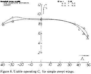
Подпись:CRITICAL ANGLE OF SWEEP. In considering the usable operating CL of swept wing, tip stalling is generally the major factor as this leads to the unstable pitch up mo­ment. The combination of aspect ratio and angle of sweep influence the stall and thus the moment.

Thus, for any aspect ratio an angle of sweep can be identified above which a pitch up moment wC be en­countered. Based on experimental data (3) the range of aspect ratio and sweep angle for a stable pitching moment curve was established, figure 9.

DATA FROM (5, b)

CHARACTERISTICS AT HIGH ANGLES OF SIMPLE SWEPT WINGS

(3) Aspect Ratio Effects:

a) Turner, Sweep and Aspect Ratio Effects on CLx, NACA TN 3468.

b) Also (l, a) (1 ,e) (l, g).

For a given wing aspect ratio the critical angle of sweep can thus be determined from the data of figure 9. The curve of critical angle of sweep shows that smaller angles must be used with the higher aspect ratio wings. This is caused by the increase of boundary layer flow which increases the section CLX in a greater proportion inboard than at the tip. Typical swept wing airliners have aspect ratios in the range of 7 to 8. Based on this aspect ratio the permissible angle of sweep given on figure 9 would be around 20°. Since an angle of yaw must be considered of at least 10°, say during a sharp turn, we are therefore left with a permissible sweep angle of only 10°. Modern airliners, for instance the 7X7 series, DC-X types, and fighter aircraft have sweep angles from 25 to 40 plus degrees. Thus, the simple swept wing must be modified for satisfactory operation.

CHARACTERISTICS AT HIGH ANGLES OF SIMPLE SWEPT WINGS

Figure 10. Drag characteristics of a typical jet transport airplane as a function of speed, wing loading and stall ratio (4).

DRAG AT MAXIMUM LIFT. For a typical swept wing airplane as the ratio of flight speed to the stall decreases, the drag also decreases (4) reaching a minimum at V0 /Vs = 1.3, figure 10. With a further decrease of speed, the drag then increases due to the increase of separation as stall is approached. This increase in drag with decreasing speed causes a speed instability condition that results in a loss of speed and lift unless corrective measures are used, such as a rapid increase of power. When landing in poor weather, the pitch up moment in combination with a smooth gradual stall and drag increase can produce a disaster, especially if the engine response time is low.
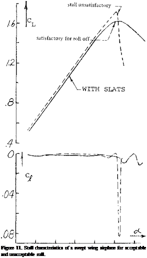
Подпись:0 8/6 24-

LONGITUDINAL STABILITY. The pitch up moment due to stalling at the tip of a swept wing will result in an unstable aircraft. Thus, as noted in Chapter XI, instead of returning to a lower angle of attack due to a disturbance as with a stable configuration, the angle will become larger increasing the stall. For airplanes operating in the take off and landing range the wing designer has the choice of many different combinations of high lift devices to devel­op a stable configuration as noted in the section “Design for High CLX ”. To develop a wing with a negative pitch­ing moment in those combinations of A and A exceeding the critical angle of sweep, figure 9, the load distribution must be changed so the inboard sections stall first. As noted later in this chapter and (5), the shifting in load to the inboard sections is impossible with some very high sweep angles and aspect ratio combinations. However, improvements of usable operating lift coefficients of swept wings can still be achieved. This can be done with leading edge extensions, slots and in some cases fences.

(4) Fischel, Low Speed Operation of Jet Transports, NASA M 3-1-59H.

LATERAL STABILITY. Separation at the wing tips and the associated stall is especially undesirable from lateral stability considerations. For instance, if the stall is es­pecially sharp a small change in angle of attack on either wing of an aircraft can cause stall with an associate sharp roll off (6,a). This, as in straight taper wing aircraft, results in unsatisfactory flying qualities. Shown in figure 11 is the variation of lift for a wing with A =35° that in unsatisfactory flying qualities. By using leading edge mod­ification fences the shape of the curve was made more rounded and satisfactory lateral stability characteristics were obtained. Separation at the wing tip also causes the ailerons to become ineffective. In fact, it is noted that several transport aircraft have two pairs of ailerons, one at about 1/2 span, figure 35.

STALL OF SWEPT FORWARD WINGS. As shown in Chapter XV, figure 8 swept forward wings stall near their center sections first, (l, g). This characteristic is desirable from control considerations as the outboard sections are free from separation and the lateral control devices remain effective. Thus, it can be expected that lateral stability and control will be retained with aircraft equipped with swept forward wings. It can also be hoped that the early flow separation, such as is shown on figure 12, will give the pilot a clear warning and provide a pitch down mo­ment by the way of reduced downwash at the horizontal tail surface.

Although the stall of swept forward wing occurs first on the inboard station the unstable pitch up moment is still encountered after the wing sweep angle and aspect ratio exceeds the critical value shown on figure 9. A compari­son of the moment curves for swept forward wing with A = 46.6° and 60° given on figure 12 confirms this. The separated flow encountered inboard with swept forward wings will also lead to buffet problems, especially at high speeds. The loading about the wings elastic axis also can possibly lead to structural problems, as the wing will tend to twist up in angles which could lead to aeroelastic problems.

(5) Elimination of Pitch-Up Swept Wings:

a) Weil, Design Studies, NACA RM L53123c.

b) Furlong Summary of the Low-Speed Longitudinal Charac­teristics of Swept Wings, NACA TR 1339.

(6) Lateral Characteristics of Sweep Wings near Stall:

a) Anderson, Roll-off in Low-speed Stalls on a 35 Swept Wing, also fences, NACA RM A5 3G22.

b) Goodson, Ailerons on Variation of Swept Wings, NACA RM L55L20.

FUSELAGE INTERFERENCE. Due to the increased wing loading of high speed swept wing airplanes the fuselage is often much larger in relation to the wing than some of the slower aircraft. Therefore, the fuselage interaction with the wings becomes an important factor in its effect on load distribution, CL* , flow separation and buffet. At low Mach numbers, (7,a), during takeoff and landing the body adds to the lift in terms of the lift produced by itself and that induced on the wing. The induced lift disappears at CLy but the body lift can increase the maximum by as much as 15% for the zero flapped condition, figure 13. The actual value of L CLX will depend on the body size and the sweep angle, since the sweep angle will determine the angle at stall and the body lift will increase with an increase of angle of attack. At the low speed condition the body has only a small effect on the wing load distribution, especially near stall (7,a).

The overall effects of the fuselage on the lift coefficient where the pitch up moment becomes positive are small (7,b) even with large changes in shape and wing location. Also, changes in fuselage shape and wing location ap­peared to have little effect on the variation of pitch up moment as the stall is approached. The main influence of such changes on the stability of the aircraft was in yaw as discussed in Chapter XII.

FREE STREAM

CHARACTERISTICS AT HIGH ANGLES OF SIMPLE SWEPT WINGS

Figure 12. Swept forward wing lift, moment and stalling character­istics (l, g).

CHARACTERISTICS AT HIGH ANGLES OF SIMPLE SWEPT WINGS

CHARACTERISTICS AT HIGH ANGLES OF SIMPLE SWEPT WINGS

Figure 13. Division of wing and body lift.

The fuselage shape and contour at the wing junction has a large influence on the level of usable lift coefficients of a swept wing operating at high Mach numbers. Tests have indicated that with proper modification of the wing junc­ture, using the methods of (7,c, d) important improve­ments in pitching moment characteristics, drag and slope of the lift curve can be obtained at high speeds. The largest effects of the change in contour occur at Mach numbers above the critical.

DYNAMIC STALL. In Chapter IV it was shown that the maximum lift of straight wings is influenced by th e rate of change of the angle of attack. Tests (8) indicate that the rate of change of angle of attack also increases CLX – for swept wings. For ~A~- 35° the increase of CLX is larger than for a corresponding straight wing, figure 14. The hysteresis loop developed by straight wings, figure 28, Chapter IV, would also apply for swept wing.

CHARACTERISTICS AT HIGH ANGLES OF SIMPLE SWEPT WINGS

CHARACTERISTICS AT HIGH ANGLES OF SIMPLE SWEPT WINGS

Figure 14. Dynamic stall effects for swept wings.

PREDICTION OF SWEPT WING STALL. In the design and analysis of swept back wings it is necessary to predict the wing operating CL at which stall takes place. Such procedures are needed to find the conditions where wing section stall may induce a pitch up moment and the effects of wing modification used to delay stall. There are several methods of analysis (2,a, c,d, e) that have been developed for finding the load distribution of wings as a function of planform, twist, section camber and operating conditions. These theoretical methods are based on span loading and lifting surface theories and predict the results with good accuracy at conditions below CLX.. Thus, for instance (l, d) can be used to calculate the load distribu­tion variation as a function of operating CL for any swept back wing. If many calculations are required high speed computing machines are used with (l, c) or (l, e).

(7) Fuselage Interference:

a) Martina, Body Effects on Spanwise Load, NACA TN 3730.

b) King, Effects of Cross-Section Shape and Wing Height,

NACA RM L55J25.

c) Kudemann, Design of Wing Function for Swept Wing at

High Mach Numbers, RAE 2219.

d) Weber, Design of Wing Function, cont., Addendum RAE

2219.

e) McDevitt, Body-contouring at Root Sweptbaek Wings,

NACA TN 3672.

In Chapter XV it was shown that the pressure distribution could be accurately predicted on a swept wing section from two dimensional airfoil data. This is done based on the simple sweep theory which shows that a wing section normal to the quarter chord line has the same characteris­tics of a two dimensional wing if the conditions are based on a component of free stream velocity normal to the quarter chord line. This simple sweep theory appears to apply with good accuracy when operating below the stall angle. However, as noted in figure 7, the three dimen­sional flow improves CLX to values much above those predicted used in tv/o dimensional airfoil data. This is especially true on the inboard sections of the wing. Thus, if the procedure (9,a) for finding first occurrence of stall is based on the calculated load distribution of (l, c) and two dimensional data, the predicted value of CLx will be much lower than measured. Since the improvement of CLx of section data due to sweep cannot be predicted by theory it will be necessary to use the two dimensional data as given in Chapter IV to estimate where stalling first takes place. The section stall data should be for the Reynolds and Mach numbers based on the velocity com­ponent normal to the quarter chord line of the wing. Also, in accordance with the simple sweep theory the airfoil section is that normal to the wing quarter chord line.

An example of the load distribution for a swept wing is given on figure 15. Based on simple sweep theory the corresponding section stall is also shown. Based on these two plots the wing would be estimated to first stall at the semi span station El – .68. The boundary layer flow increases the CLX as shown so that the actual first stall is located at M = .79.

The calculated lift coefficient where section stall is first encountered on a swept wing is lower than measured by approximately.01 as indicated in (9,a) or about 20%. The trend with changes in sweep angle and aspect ratio appears to be good so that the effects of changes can be expected to be determined with reasonable accuracy.

(8) Dynamic Stall:

a) Conner, Effect of Angle of Attack Rate on Max. Lift, NASA CR 321.

b) Rainey, Stall-Flutter Thin Wings, NACA TN 3622.

(9) Review Reports:

a) Harper, Stall Characteristics Swept Wings, NASA TN D2373.

b) Toll, Longitudinal Characteristics of Wings, NACA RM L5 3121b.
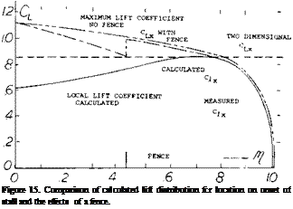
Подпись: Figure 15. Comparison of calculated lift distribution fcr location on onset of stall and the effects of a fence. Подпись:Подпись: (8)Подпись: whereAlthough the method given above is a good approxima­tion for finding the station where stall first occurs it does not give satisfactory results for estimating the spanwise load distribution at high angles. This is due to the large increase of lift coefficient, especially on the inboard sec­tions as shown on figure 7. For wings with. Л. = 45° analysis of (10,b) indicates the load distributin’! at high angles can be approximated by the equation

15 -(50-000’ 15 + (50 – QL)/T

= The airfoil normal force coefficient, or: = Wing angle of attack. ft – Semi span distance from mid span = .5, ft’ is minus inboard of ft = .5 and plus outboard.

With the equation 8 and the distribution function shown on figure 16 an approximation of the load distribution on the wing operating at high angles of attack can be found for a known value of C* The distribution function of

(10) Spanwise Load and Section Lift Swept Wings:

a) Hunton, Section Characteristics of Two 45 Swept Wings, A = 6, NACA TN 3008.

b) Axelson and Haacker, A 45 Swept Wing with Body Combinations, NASA Memo 1-18-59A.

c) Graham, Low-speed Tests 45 Swept Wing, A = 3, R to 4.8 x 10 , NACA RML51H13, also TR 1208.

d) Hunton and James, Use of Two Dimensional Data in Predicting Loading with Flaps, etc., NACA TN 3040.

e) Woodward, Swept Back Wing With Constant Cu A= 35 , RAETR 71050.

figure 16 was set up for-A – = 45° and strictly applies only for wings with this angle; however, it is believed that it will be suitable for wings with sweep angles of 35 to 50 degrees.