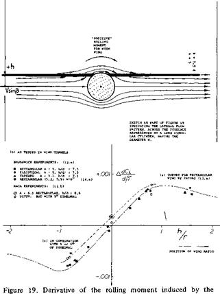
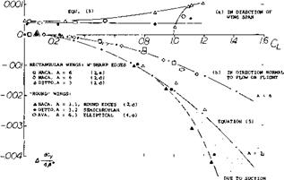
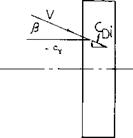
Category FLUID-DYNAMIC LIFT

STALLING OF SWEPT WINGS. (PITCHING, ROLLING AND YAWING)

The stalling characteristics of airfoil sections and straight wings along with the maximum lift coefficients are dis­cussed in Chapter IV for single element airfoils. The effects on CLX by the use of trailing edge flaps, leading edge slats and other high lift devices are covered in Chap­ters V and VI. These chapters provide the necessary basis for the study of the stall characteristics of swept wings which are very different from those of straight wings, especially when operating at high angles of attack. The stall, maximum lift, moment and drag characteristics of swept wings are generally very unfavorable and thus spe­cial attention is required in the design to achieve satisfac­tory flying qualities. The unfavorable high angle anc. stall characteristics of swept wings are accepted because of their good high speed performance and associated higher Mach number prior to the drag rise qualities discussed in Chapter XV and in the book “Fluid Dynamic Drag”.

The variation of the pitching moment with angle of attack when operating at or near maximum lift is one o: the major problems of swept wings. This problem is caused by an unstable pitch up moment of the wing at both high and low Mach numbers which leads to unsatisfactory aircraft flying qualities. For this reason, when considering the maximum lift and stalling characteristics of swept wings the variation of the pitching moment becomes of major importance.

The flow characteristics effecting the stall properties of swept wings are influenced by the aspect ratio, sweep angle, load distribution, planform and operating condi­tion. The wing design modifications used to obtain satis­factory operation are covered. These design modifications will include the use of planform changes, flaps, slats, camber, wash out, spoilers and fences. Where possible the data will be given for estimating the effects of Ihese aero-dynamic devices on the stalling characteristics of swept wings.

Definitions: Aspect ratio, taper ratio and sweep angle are defined as in Chapter XV. A simple or plain swept wing is considered to be an untwisted wing of straight tapered planform with no span wise variation of airfoil sec: ion. Such simple straight wings are also considered to have low camber airfoil sections.

LIFT OF SWEPT WINGS

Г"*

Подпись: (35)Подпись: 30-Подпись: л = 0 M = .5 Подпись: /0 -

It must be noted, however, that because of wind-tunnel interference, values higher or lower than indicated can be found in various references. For practical purposes, equa­tion (33) is suggested to be sufficiently accurate. It shows that the sectional lift angle is as indicated by equation (31). For example, for M = 0.9, and j/4 = 35 as in the F-86 fighter airplane (24) the two-dimensional pa rt of the lift angle is reduced, as against conditions in incompress­ible fluid flow, by some 3° . In spite of the angle of sweep (increasing the lift angle by almost 2° ) the lift-curve slope is increased in this example. The reduction of the angle due to compressibility amounts to some 5° , from that of the same wing (with A = 4.8) in incompressible fluid flow, in the order of do/ /dCL = 14° ; the result is do6 /dCL = 11 , or = 10 , when considering the influence of the fuselage. This result agrees with flight-test and full-scale wind-tunnel data reported in (24).

LARGER ANGLES OF SWEEP. Evaluations similar to that in figure 22 can be made for different aspect ratios and angles of sweep. On the basis of equation (21) it can be expected that the lift angle may be increased by a component proportional to l/cos2J . Figure 23 exhibits a single point for A = 522 and M = 0.8, showing about 60% of the increment as given by the equation. It is suggested again that viscosity (boundary layer accumulation on the wing tips) is responsible for the deterioration of the few experimental points at angles of sweep between 50 and 60° (see also figure 24). In fact, atV = 60 , where cos7 = 0.5, the effective thickness ratio of the wing sections (in the direction normal to the panel edges or axes) is twice that of a straight wing. The boundary layer is also in­creased in thickness by the velocity component (V sinV) along the panels. The type of flow pattern thus developing will be further discussed in Chapter XVI.

ASPECT RATIO. Disregarding the possible influence of viscosity (creeping flow separation in larger angles of sweep, as above) the most suitable lift formulation, for swept wings with aspect ratios between zero and infinity, is as in (11,a) similar to that in figure 12. Experimental

results in figure 24 do not readily confirm the theoreti­cally expected lift-curve slopes. The spread is up to + 10% and — 5%. Examination of the experimental conditions leads to the following statements:

a) In combination with fuselages, lift is markedly in­creased. Using equation (22) a body diameter d = 0.2 b would explain a 10% increment.

b) There are several inconsistencies in the data plotted. It can be assumed that wind-tunnel blockage or other test conditions are responsible.

c) The points evaluated from tests in (25,a) show good correlation between a 47 7 swept and an essentially straight wing.

d) As in figures 12 and 20, half-span wings have low lift coefficients. However, when tested on a bump, their lift is on the average as high as expected by theory.

e) Reference (25,b) although affected tunnel blockage, gives a comparison between wings swept to plus and minus 35 and 45 . Correlation as shown in the graph was only obtained, however, after changing the consequence of equation (20) into

A A°= — 25/A

о VARIOUS SOURCES (23)

do<г/dCL x A = 3.5, CORRECTED (23,b)

+ A = 4, CORRECTED (22, g)

Л =. 45° + 52°

20-

Л.= 60°

M = 1.0

da^dC^ *10 j – (M cos/t+)2/cos/+

doCi/dCL = 20/3 = 7° //COS A

. i___ і__ і___ j___ l___ і___ і___ і_ 1 … – Ti—

‘0 .2 4 .0 – S /0 /2 !A f£ i. Q 2.0

LIFT OF SWEPT WINGS

Figure 23. The lift angle of swept-wing-fuselage combinations with A = 3, and M cos =0.5.

CRITICAL MACH NUMBER. As discussed in Chapter VII, the critical Mach number is theoretically that at which at some point, usually at the upper surface of a lifting wing, the local velocity is equal to the sonic speed. Upon exceeding the critical Mach number, forces and moments are likely to show variations different from

(25) Subsonic characteristics of various swept wings:

a) Silvers, Wings With Missiles, NACA RM L54D20.

b) Whitcomb, Wing Plus/Minus 45°, NACA RM 46J01a.

c) Sutton, With Body Contouring, NACA RM A1956J08.

d) Goethert, Lil’thal Rpt 156 (1943); NACA TM 1102.

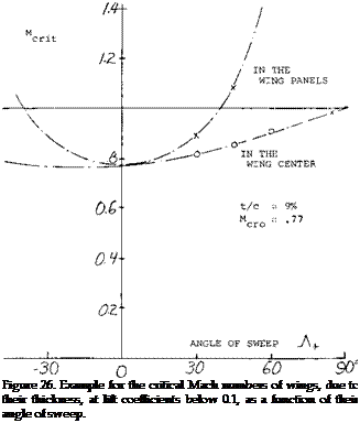
Подпись:Подпись: C) HALF-SPAN WING MODELS 0 WITH1/2BODY (15,b) (25,c) • A = 45°, A = 4 (22,d) * A = 47°,A = 3.5 (23,f) 1 WITH TUNNEL BLOCKAGE(25,b) o A = 0, 1/2 ON BUMP (27) Д VARIOUS WINGS ON BUMPCB.b) A A - 40°, OUTSIDE FUSELAGE (26,c) Подпись:Подпись:those at lower speeds. According to the cross-flow prin­ciple of swept wings, the sonic speed first to be encoun­tered in their panels corresponds to M = 1/cos. A, where Л may be equal to 7^. , determined as per equation (20) or (35). Considering, however, a reduction of the critical speed due to thickness (say t/c = 9%) at some small lift coefficient (say CL = 0.1) the corresponding Mach num­ber would be in the order of

Mcr. it = 0.77/cos A (36)

It is seen in figure 23, how this upper number can grow into the supersonic range. At – Л+= 40 , the critical number in the wing panels is M = 1, in the example considered.

a) WING-BODY COMBINATIONS

I A = 4, A = О b 35° (22,b)

+ A = 4, A = 45° (10,a)

x A = З, И = 19,45,53° (23,d)

a A = 4, A = 4° (25,a)

» DITTO, A = 47° (25,a)

л A = 6, A = 35° (28,c)

H A = 4, A = 45° (22,d)

Y A = З, b = 6 (29,e)

Figure 24. The lift-curve slope of swept wings at Mach numbers between 0.4 and 0.9, as a function (16,a) of the aspect-ratio parameter “F”.

(26) Pressure distribution across the span of wings:

a) Neumark, Critical M’Number, ARC RM 2821. Transonic similarity as in this report also in Chapter XV of “Fluid Dynamic Drag”. See also ARC RM 2713 & 2717.

b) Kuchemann, With W’out Body, ARC RM 2908 & 2935.

c) Holmes, 40° With 10% Sections, ARC RM 2930.

d) Weber (RAE/ARC), Symmetrical Sections (RM 2918), Cambered Sections (RM 3026), Centre Part of Wing (RM 3098); also J/RAS 1959 p 476.

e) Cook, Comparison at High Speeds, ARC RM 3194.

0 Runckel, 45° 65A004 Transonic, NASA TN D-712.

g) See also the chord wise distributions under (5).

h) Bagley, Calculated, ARC C’Paper 675.

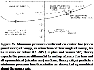
CENTER OF A SWEPT WING. In the center of a swept wing there cannot be a cross flow. As explained in (26,b) the supervelocities along the center line of a swept-back wing are usually lower than in the wing panels, when considering conditions at zero lift. The low-speed mini­mum pressure coefficient in the wing center is plotted in figure 25, particularly for 12% thick RAE sheared foil sections (26,b) as a function of the angle of sweep. The flow around and over the apex of a swept-back wing is more or less three-dimensional. However, as a conse­quence of the flow components converging onto the cen­ter line, from the swept-back wing panels, quasi-two – dimensional conditions are obtained along most of the way toward the trailing edge of the center part of the wing. In other words, we have to deal with the full speed

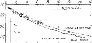
V. Taking up the example again as in connection with equation (32), figure 22 indicates for J = 40 , at low speeds, an average C p = — 2.1 (t/c) = — 0.19. Using figure 2 of Chapter VII, the critical Mach number in the center of the wing is then M = 0.83. This value is appre­ciably higher than that of a straight wing having the same airfoil section; M crit = 0.77. The two critical M’num – bers are shown in figure 26 as a function of the angle of sweep. Points derived from pressure distribution data (26,b) agree with transonic similarity theory (26,a) after taking into account the difference between “sheared” and “yawed” thickness ratio. It must be remembered, how­ever, that reaching the critical M’number does not yet mean a divergence of forces. Drag-divergence Mach num­bers of swept-back wings for zero (or sufficiently small) lift coefficients are plotted in figure 27, using the correla­tion as in (28,b). These numbers can be some 5% higher than the critical values. The graph suggests that the delay of divergence (but not the divergence Mach number as such) increases with the thickness ratio t/c.

-66 -40 -го о го 40 oo’

Подпись:WING ROOTS. Considering conventional airplane config­urations, there is necessarily a fuselage covering the center area of a swept wing. As demonstrated in “Fluid Dynamic Drag”, whatever is done to the shape of slender bodies their critical speed is below M = 1, say at M = 0.95. Subsequently, they are exposed to supersonic velocities along their surface, and recompression becomes deficient. Regarding the interference with the two panels of a swept wing, theoretical and experimental results reported in (26) indicate that the panel roots adjoining a more or less cylindrical fuselage body, exhibit at zero lift, approxi­mately the same pressures and distributions as described above for the center line of a wing alone. A few wing-root points are included in figure 25. In fact, in a particular configuration (23 ,f) the wing root thickness can be in­creased to critical or divergence Mach number (at zero lift). This result will change, however, at positive lift coefficients (say above 0.2) where the wing roots are bound to become more critical in the two-alpha flow induced by the fuselage. Also, considering the super­velocities along curved fuselage shapes, pressures along the wing roots must be expected to be lower than in the panels.

LIFT OF SWEPT WINGS

Подпись: c) HALF SPAN ON WALLПодпись: + (25,b)Подпись: t/c "SHEARED1 (PARALLEL TO CENTER LINE) Подпись:LIFT OF SWEPT WINGSПодпись: 35° SWEEP Подпись: WITH BASIC BODY W1CONTOURED BODY MDD = 0.85 = 0.89 DRAG DIVERGENCE *LD = 0.84 = 0.86 LIFT DIVERGENCE MD.3 = 0.82 = 0.84 DRAG AT CL = .3

a) WITH FUSELAGE, WING ROOTS

о (10,a)(22,e) (25.a) (28,a) □ (23,d, e)

■ (23,f)

$ (22, b)

A OTHERS

b) HALF SPAN ON BUMP

о (25,b) x (28,b)

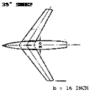
Figure 28. Example (28,c) of fuselage contouring, intended to increase the critical or force-divergence Mach number of swept wings. The indentation is shown along the wing roots as a pair of heavy lines.

CONTOURING (29). Figure 28 shows how suitable con­touring of the fuselage walls (similar to that according to the transonic area rule) makes room for the typical panel cross flow to develop. The critical Mach number of the wing roots may thus be increased, from the lower bound­ary as in figure 26 possibly to the supersonic values as in

(27) Nelson, Straight Wings on Bump, NACA TN 3501, 3502.

Подпись: Cpr.ln =-0.31 = -0.25 = - 0.23 = -0.19 = - 0.22sufficiently swept panels. The fuselage retains its critical subsonic Mach number, however. Critical flow conditions of any swept wing, or wing-fuselage combination, are thus always reached below M = 1. By suitable contouring or shaping according to the transonic area rule not a subject of this text, but see (1) for example expansion, recom­pression and shock formation along the body may be kept harmless. As an example (26,b) pressure coefficients on the roots of a wing with t/c = 12%, at CL = zero, and at low speeds, are quoted as follows:

straight wing with cy lindrical fuselage same wing with contoured fuselage in panels of 45 0 sheared wing roots of 45° wing with cylindrical body roots in presence of contoured fuselage.

In case of a lifting wing (to be discussed below) contour­ing can be applied above the wing roots (2,c) thus making room for the converging streamlines at the upper side. As shown in (29,d) a similar effect is obtained when placing the wing panels on top of the fuselage (high-wing).

FUSELAGE INTERFERENCE. At an angle of attack, the roots of any wing (straight or swept) are considerably affected by the fuselage. As explained in Chapter VIII of “Fluid Dynamic Drag and Chapter XX, any cylindrical body produces a two-alpha flow, resulting in upwash at the wing roots. As a consequence, pressure distributions as in (26,f) and (29,a, b) exhibit peaks near the leading edge of the panel roots beginning at C = 0.2 in a symmetrical, and at C = 0.4 in a 5% cambered section (5,c). Aided by the spanwise boundary-layer flow (described in Chapter XVI of this text) lift coefficients on the wing roots can thus be very high, say twice as high as in the remainder of the panels. In thin and symmetrical wing sections, these pressure peaks are cut down considerably by laminar separation. As shown in (26,f) and (29,b) the load distri­bution, as in figure 6, is nevertheless filled up to an essentially elliptical shape; and this fuselage effect is the reason for increased lift-curve slopes mentioned in con­nection with figures 13 and 24. Wing-root pressure distri­butions (29) vary corresponding to section thickness be­tween 3 and 9%, and camber between 0 and 5% of the chord. Minimum pressure coefficients differ considerably, and it is impossible to find any reasonable correlation. It can be argued, however, that local supersonic “spots” developing on the wing roots at higher subsonic Mach numbers will not have any noticeable influence upon flow pattern and lift of swept-back wing-fuselage combinations. Disregarding, therefore, these peaks the minimum pressure coefficients found around 40% of the root chords of swept-back wings, may be said to be in the order of

Cpmm = – 2 (t/c) cos2W — KCL (36)

where CL = average wing coefficient, and К in the order of 0.4 for symmetrical sections with t/c = 4%; about twice that high for t/c = 7%; and up to 1.2 for properly cambered root sections. Thin and sharp leading edges thus lead to more or less local separation, while rounded and cambered sections permit the two-alpha flow to produce high lift with extended low-pressure areas developing on the wing roots.

CRITICAL LIFT. As suggested in (26,a, b) the full speed V, and the Prandtl factor as in figure 1 of Chapter VII, have to be considered in the center or on the roots of a swept wing. Therefore:

Cpmm" C p mine/ JT~—~М~г (37)

where C p mine = incompressible coefficient, for ex­ample as in equation (36). It should be noted that the pressure coefficient on the wing roots grows as a function of Mach number, at a higher rate than any coefficient in the swept panels (as in equation 36, or as shown implicitly in figure 26). For statistical purposes (as in figure 29) it is suggested to use К = 1, in the last equation. As explained before, a subsonic flow pattern can be maintained in the panels of swept wings, say between 0.3 and 0.9 of the half span, at lift coefficients below 0.1 or 0.2, up to Mach numbers in the order of (0.8 cosy). For example, it is demonstrated in (28,e) that the cosine principle still holds at a Mach number of 1.2, in the outboard 75% of the half span of a sufficiently swept-back wing, at or near zero lift. Flowever, when really lifting, a negative pressure ridge appears in the wing panels, near their leading edges, when using essentially symmetrical wing sections. As shown in figure 6 of Chapter VII, it is statistically and approxi­mately (for low lift coefficients, and at low speeds):

Cp mm =-C * /(t/c) (38)

In the panels of a swept wing, we have to substitute, Corresponding tO the COSine principle: (Cpmtn /cos2A ) for (CP mm ); (Cu /cos*LA ) for (CL); (t/c)/cosЛ for (t/c); (M cos7) for (M). Equation (38) thus reads, for a sheared wing:

CPm(n/cos2A = (Cl/cos2A)2′ cos A/(t/c) (39)

(28) Flow and forces above critical M’number:

a) Whitcomb, 65A006 / A = 4 / 45°, NACA RM L1952D01.

b) Polhamus, Transonic Bump Results, NACA TN 3469.

c) VonKarman, Similarity, J Math Phys 1947 p 182.

d) Ackeret, Swept High Speeds, NACA TM 1320.

e) Bagley, Shape and Drag, ARC C’Paper 512.

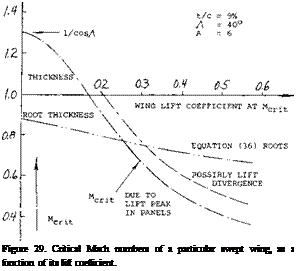
Подпись:Подпись: M = 0.6Using the Prandtl factor corresponding to /l — (M cos./if (see figure 1 of Chapter VII) the critical Mach number (M cosA) is then found in figure 2 of the same chapter for (C p min /cos2_A ). Confirming the procedure, a set of experimental points obtained on a 45° swept wing, was reduced to A =0, and included in figure 6 of Chapter VII. The result is of the same type as the upper boundary in figure 26. This means that the critical num­ber M cm = (M cosA)/cosA, can still be supersonic. As an example, a wing with t/c = 9%, and A = 40 , was evaluated regarding critical Mach number. As shown in figure 29, the critical number in the wing panels is highest at lift coefficients below 0.25. In fact, the permissible speeds remain supersonic up to CL slightly above 0.15. Within the range of smaller lift coefficients, force diver­gence is first caused by high speeds (low pressures) on the wing roots. We have plotted a line using К = 1 in equation

(36) . In conclusion, the cosine principle (being the foun­dation of swept-wing design) does not necessarily prevent supersonic velocities and their consequences (drag, shocks, buffeting) along the wing roots. However, contouring of the fuselage body as described above can possibly produce a flow pattern over the upper side of the wing roots, similar to that in the wing panels. Even then, the body itself is bound to retain a subsonic critical Mach number (say M = 0.95); and the body will pay a penalty (say at M = 1, by supersonic expansion, recompression through a shock, and drag) for letting the wing remain subcritical.

FORWARD SWEEP. The most interesting fact to be noted in figure 25 and 26 is the sensitivity of the center of swept-forward wings. As shown in (12,e), the minimum pressure on center line (at zero lift) is approximately:

Cp fr>iг) = — 0-25, atx/c = 0.37, in center 45° swept-back = – 0.27, at x/c = 0.25, average in wing panels = — 0.60, at x/c = 0.03, center 45° swept-forward

It is thus seen how the swept-forward panels induce con­siderable supervelocity near the leading “edge” of the wing center. This situation becomes even more pro­nounced when lifting. As shown in figure 6, lift and lift coefficient are concentrated in the center of a swept – forward wing. Experimental results reported in (I2,e) indicate peaked minimum pressure coefficients near the leading edge of the center of a 30° swept wing, roughly as follows:

Cpmir, = – 0.3, for swept-back panels

— 0.6, for the straight wing

— 1.2, swept-forward panels.

Conditions of the tunnel tests were as follows:

wing yawed 30 from yawed airfoil section lift coefficient approximately Mach number of testing

Although the result cannot be generalized, the value of Cpmm in the center when swept-back is in the order of half of that for the straight wing and twice that high in the swept-forward condition. The corresponding critical Mach numbers at the center (or on the wing roots) are in the order of

M CRJT = 0.8, for yawed-back panels = 0.7, for the straight wing = 0.6, for yawed-forward panels.

In conclusion, the swept-forward type of wing is not promising in regard to critical speed. It must be said again, however, that forces do not necessarily diverge at The critical Mach number. The drag coefficient in the roots of the wing just quoted is only CD = 0.015, at M = 0.8, in comparison to 0.008 in the panels. It is also interesting to note that the center of a 45 swept-forward wing tested (12,g) at low speed, stalls at C L = 0.5, while the lift-curve slope continues to CL =0.7, and the maximum is C Lx =

1.0. Similar conditions are seen in figure 8. Local drag coefficients at the wing roots can then (12,e) be up to 10 times as high as in the panels.

ENGINE NACELLES. When the engine nacelles is built into the panels, the interference effect upon swept wings is similar to that of a fuselage. In fact, in a swept-back wing the inboard junctures (corners) have a flow pattern similar to that in the center of a swept-forward wing. Low pressures are-concentrated in a peak near the leading edge. This condition is aggravated at any lift coefficient differ­ent from zero or “symmetrical” (see Chapter II). Even without the help of compressibility, flow separation (as in part (b) of figure 8) is easily encountered. As an example, pressure distributions around an engine nacelle (16,a) in­stalled in a 35 swept-back wing, with 12% sheared sections, show at = 0.3, peaked minima at the inboard side, more than twice as high as in the outboard corner.

(29) Pressures along roots of swept wings:

a) Mugler, Wing + Body, NASA Memo 10-20-1958L.

b) Cassettim 53° Swept Transonic, NASA TN D-971.

c) McDevitt, Body Contouring, NACA RM A1955B21.

d) Dickson, Wing-Fuselage Height, NACA RM A55C30.

e) McDevitt, Investigation of Fuselage Contouring on Wing – Body Combinations, NACA RM A1957A02.

0 Contouring first tried at DVL (4)(25,d)(26,b).

By comparison, the critical Mach number in the particular configuration tested would be Mcrit = 0.6 outboard, but below 0.5 inboard. Another example (21 ,c) with 45 sweep, using 65A006 sections, shows at CL = 0.3 a drag divergence number Mq = 0.96 without nacelles, and M = 0.92 with nacelles. Some creeping divergence is evident, however, beginning at M = 0.8.

HIGH-SPEED PERFORMANCE. From what is said in this section regarding critical Mach number it can be con­cluded that the gain in maximum cruising speed of air­planes through the use of swept wings is limited, see figures 26 and 29. Modern airliners may, on the average, be operating as follows:

having an aspect ratio A = 7, with some 30 of sweepback, cruising at coefficient C L =0.3, at an altitude of 9 km, 30,000 ft. critical Mach number below 0.8, maximum M’number, approaching 0.9.

Подпись: Figure 29. Critical Mach numbers of a particular swept wing, as a function of its lift coefficient. If their speed is up to 1000 km/h (some 600 mph, oi above 500 knots) that must be compared with some 700 km/h (or less than 400 knots in the previous generation of (straight-wing and propeller-driven) transport airplanes. Upon inspecting figure 26, it can then be concluded that the increase of cruising speed was brought about not just by sweepback, but also by jet propulsion. In aerodynamic respect, consideration of range (as in Chapter I) would call for a cruising lift coefficient in the order of 0.35. As indicated in figure 29, the critical Mach number for this coefficient might only be between 0.6 and 0.7. On the basis of experimental results such as in (26,c) for example, the permissible coefficient for M = 0.8 may be noticeably higher than indicated by MCRlT, say at least CL = 0.3 . A weak and evidently harmless shock front can be seen across the wing panels (under favorable conditions of sunlight) by airline passengers prepared for the phenomenon.

INFLUENCE OF COMPRESSIBILITY ON SWEPT

2. The second version has the advantage that the effective WINGS. angle of sweep (equation 29) does not have to be com­

puted.

When used in subsonic airplanes, the critical Mach number of swept wings is of primary interest. However, as in other wings, compressibility also affects the aerodynamic forces at speeds below the critical.

ANGLE OF SWEEP. As in incompressible flow, the lift of a swept wing is approximated by that of the two panels, say at Уг of their span, exposed to the components of the air speed each normal to their quarter-chord or equal – pressure axes; that is to (V cos/) as in figure 2. However, as pointed out in (21,b, c) the Prandtl-Glauert rule (see Chapter VII) can also be formulated as saying that any wing in compressible fluid flow produces the same lift as a wing whose dimensions in the direction of flow have been increased in proportion to the Prandtl factor P = 1/ /1 — M*. This means that not only the chord, but also the angle of sweep of that reference wing are increased. Accordingly, the effective angle (subscript e) corresponds to

tan j^= tan _Л+/ Гі — M2 (29)

It then follows that

cos 7еУі — (M cos – cos Ар/ 1-М2 (30)

where У1 — M2 as in Chapter VII.

LIFT ANGLE. Based upon the foregoing and equation (21) the lift-curve slope of a swept wing with infinite aspect ratio, in a compressible fluid flow, is expected to be

Assuming now that the induced drag and the angle due to lift (20/A) are no larger than in straight wings, the lift angle of swept wings with higher aspect ratios (say above A = 4) is

d<X° IdCL = (10 /l – (M cos A+f /cos – Л+) + (20/.A)

(33)

where (M cos Л*) can be considered to be an effective Mach number, for which the root in the equation can be taken from figure 1 in Chapter VII. Available experi­mental data are plotted in figure 22. While evaluating the many sources as in (22), it was found that on the average, wings tested in combination with a fuselage have doL /dCL values larger by 1° , and half-span wing models (mounted on the wind-tunnel wall) have values lower by

о о

1 , than plain 45 swept wings. However, results ob­tained on half wings, placed on so-called bumps in wind tunnels or on the wings of flying airplanes as in (22,c, h) for example are not affected by the thin boundary layer developing over those bumps. To obtain one single line, 20/A = 5° plus/minus 1 was subtracted from the re­ported lift angles; and the parameter of the section, ex­pected to be

(do/ /dCL) cos – Л+= 10° й – (M cos Л)2 (34) was plotted accordingly, figure 22, with promising results.

о 65A006 W’BODY (22,a)

/ W1 BODY ON STING (22,b)

+ 1/2 SPAN ON BUMP (22, c)

о Rc = 3(10)6, ВОШ(22, d) x 65A006 W1 BODY (2 2,e) ф W1 TRIMMED H’TAIL(22,f)

V DITTO, ccs/A= 0.8 (22 , g) о HALF-SPAN MODEL (22,d)

— HALF WING(BUMP) (22,h)

dCL/doc°2 =0.1 cos Л//1-М2)

dCL /doc°2 = 0.1 cos – Л I Vl — (M cos – Л+)г (31)

where 0.1 = (dCL jdoC° ) of a straight wing, with subscript 2 indicating two-dimensional conditions of flow. The lift angle is accordingly:

do /dCL= 10/1 – Мг /cosAc= 10/ГАМ cos A)* /cos A.

(32)

10 h,

(d0(o2/dCL)cos/1f

8-


INFLUENCE OF COMPRESSIBILITY ON SWEPT

Mcos//+- 0.8


6~


INFLUENCE OF COMPRESSIBILITY ON SWEPT

PARAMETER


A


(Mcos/Л^)2


INFLUENCE OF COMPRESSIBILITY ON SWEPT

__J___________________ I

0.4 0E


03


INFLUENCE OF COMPRESSIBILITY ON SWEPT

(21) Principles and rules for compressible flow:

a) Liepmann, “Elements Gasdynamics”. Wiley 1957.

b) Diederich, Correlation, NACA TN 2335, as (1 l, a).

c) Goethert, Bodies, Ybk D Lu 1941; NACA TM 1105

d) Kuchemann, Bodies of Revolution, J Aeron Sci;

Cp/Cp, nc = AV/V = ‘Fr = 1/(1 – мг A

Figure 22. Sectional component of the “lift angle” of 45° swept wings, with A = 4, as a function of the Mach number parameter.

(22) 45° swept wings as a function of Mach number:

a) Polhamus, Directional Stability, NACA TN 3896.

b) Donlan, Testing Techniques, NACA RM L1950H02.

c) Polhamus, Wings on Bump, NACA RM L51C26.

LIFT OF SWEPT WINGS

When analyzing swept wings, the angle of attack of swept wing is defined as that in the plane of symmetry, the dynamic pressure in the direction of flow or flight, and the wing span the straight distance between the wing tips or lateral edges.

Figure 4. Lift-curve slope of straight wings when sideslipp ing at an angle of yaw.

(4) The lift of straight wings when sideslipping:

a) Moller, Rectangular, Luft’forschung 1941 p 243.

b) Doetsch, Rect & Elliptical, Ybk D Lufo 1940, 1-62.

c) Schlichting, Survey, Yearbk D Lufo 1940 p 1-113.

d) Purser, Various Wing Shapes, NACA TN 2445, (1951).

e) Hansen, 5 Elliptical, Yearbk D. Lufo 1942 p 1-160.

0 Goodson, Swept Sideslipping, NACA RM L1955 L20.

(5) Chordwise distributions measured on swept wings:

a) Thiel, Straight/Swept, ZWB UM 1293, NACA TM 1126.

b) See results in references (2,a) (7,a) (7,b) (12,e).

c) Whitcomb, Isobares, NACA RM L1950K27, K28, L07.

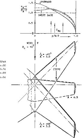
distribution across the straight wing is roughly elliptical, the swept-back shape exhibits a deficiency in the center and overloaded outboard parts. On the other hand, the swept-forward wing shows comparatively small loads on the forward ends and an overloaded center. These load distributions have severe consequences in regard to stall­ing, maximum lift, longitudinal stability (pitching up) and control (downwash and wake at the horizontal tail); and in the swept-back shape also upon roll stability and con­trol. All of these aspects are discussed later in th. s and Chapter XVI.

A) IN CENTER OP STRAIGHT V/ING

cN = o.80 C) AT 509» OP HALF

CN = °-8? CN –
LIFT OF SWEPT WINGS

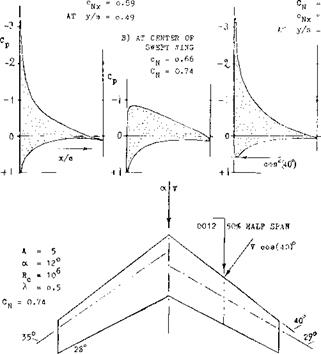
Figure 5. Chord wise pressure distributions tested (5, a) at several stations along the span of a straight and a swept wing.

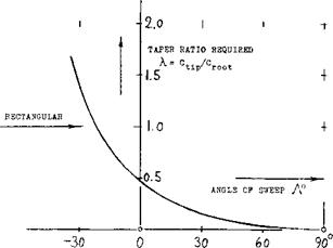
TAPER RATIO. As pointed out above, and as seen in figure 6, the load distribution of swept wings can be considerably different from elliptical. To make these dis­tributions nearly elliptical, theory (6,f) indicates the re­quired taper ratios as plotted in figure 7. For a wing swept back to Л = 30°, for example, a taper ratio of X == 0.15 would thus be needed. The idea is to give the wing more [129]

LIFT OF SWEPT WINGS

Figure 6. Load distribution across the span of three different wings (7,a) showing the variation as a function of the angle of sweep.

lift in the center and to reduce the loads on the wing tips. Necessarily this would mean higher lift coefficients (as distinct from loads (L/q) per ft or meter of span) on the wing tips. In a practical wing design, the result would be a very undesirable type of tip stalling. Aside from such considerations, references (8,a) indicates that (in the com­bination of a 45° swept wing with a fuselage) a taper ratio of 1.0 (rectangular panels) is as efficient in producing lift as 0.6 (tapered); and either one of these is better than a taper ratio of 0.3. Another method of making the lift distribution nearly elliptical is indicated in (1). The center of the wing might be given an increased angle of attack д or = A/6.

(7) Spanwise load distribution, experimental:

a) Jacobs, 4 Wings, ZWB UM 2052 NACA TM 1164.

b) Loving, Including Fuselage, NACA RM L54B09.

c) Mendelsohn, Forward & Back, NACA TN 1351; also same model with flaps, Letko TN 1352.

(8) Experimental characteristics of swept wings:

a) King, Wing-Fuselage Combinations, NACA TN 3867.

b) German ZWB Reports FB 1411 and 1458.

c) Tolhurst, Vortex Sheet 63° Swept, NACA TN 3175.

d) Cahill, Tapered A = 4, NACA RM L9J20/L50F16.

e) Kuchemann, 45° Swept Wings, ARC RM 2882.

f) Hopkins, With —40°/+45° Sweep, NACA TN 2284.

g) Goodman, Various Wings in NACA TN 1835 & 1924.

LIFT OF SWEPT WINGS

Figure 7. Taper ratios, theoretically required to make or to keep the lift distribution of swept wings as “good” as elliptical (6,f).

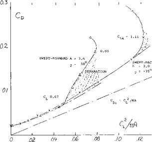
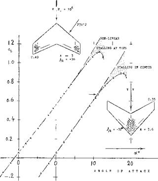
FORWARD SWEEP. If there are any over-all merits of swept-forward wings they are found in the “never” stall­ing wing tips (discussed in Chapter XVI). For finding lift the simple theory expects the cosine principle to apply in the same manner as in swept-back wings. As shown in figure 6, their spanwise load distribution is different, however. Lift and drag characteristics of a swept-forward, in comparison to a swept-back wing (having roughly the same aspect ratio), are presented in figure 8. Flow separa­tion in the center of the swept-forward wing begins around oc = 10°, where CL ~ 0.7. This is particularly evident in part (b) of figure 8. Loss of lift and growth of drag are considerable. Stalling in the swept-back wing seems to be “creeping” between C L =0.7 and 1.05. As far as the magnitude of lift is concerned, this does not have too much of an influence, however.

INDUCED ANGLE. As stated in Chapter III, the induced angle is a minimum for the optimum distribution of lift across the span of any straight wing. To account for the influence of sweep, there does not seem to be any simple method available. It follows, however, from what is pre­sented in Chapter VII of “Fluid Dynamic Drag” that the increment of the induced drag corresponds to

Act L /oCL = (к/A)A (12)

where (к/A) is a function only of the taper ratio. Using the approximation as in figure 5 of Chapter III, we find for the induced angle (rather than drag):

Подпись: A(d< /dCu ) ~ (К/A

In straight wings realistic values of K, that is for tapered wings with X between 0.4 and 1.0, may be in the order of 0.05. Equation (13) thus leads to values well below 0.1°. Considering an increment of 1% in the induced drag to be negligibly small, the possible influence of lift distri­bution may be disregarded (that is, in comparison to the various other uncertainties in any airplane configuration).

LIFT OF SWEPT WINGS

LIFT OF SWEPT WINGS

Figure 8. Lift and drag data of a swept-forward in comparison to that of a swept-back wing (9,f).

DRAG DUE TO LIFT To determine the drag due to lift as a function of angle of attack as in the set-up in figure 2, the panels should be rotated (twisted as a whole) against the center axis of the swept wing. This is done in most airplanes, at least by some 3°, to keep fuselage and passengers on a level floor when cruising. Aerodynamic rotation is also obtained when deflecting trailing edge flaps and/or ailerons. In all wind-tunnel tests, the whole wing is pitched, however, rather than rotating the wing panels relative to the center body, a perfectly plane wing, such as a swept-back flat plate, the tips drop below the level of the center. A negative angle of dihedral thus develops. The influence of dihedral as such is compara­tively small (see Chapter III). In swept wings, the lifting forces are tilted sideways, however, in addition to being tilted back by the induced angle. As found empirically (in Chapter VII of “Fluid Dynamic Drag”) the drag due to lift increases accordingly, corresponding to

dCD/dCf ~ 1 /cos. A (14)

It is believed that this increment (of induced and/or separation drag) is due to viscosity (boundary layer accu­mulation at the ends of the swept-back wing panels).

LIFT OF SWEPT WINGS

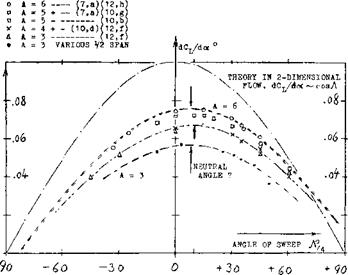
Figure 9. Lift-curve slopes of wings having aspect ratios between 3 and 6, as a function of their angle of sweep.

LIFT ANGLE. The angle-due-to-lift involved in equation

(14) would lead to the following modification of the “lift angle” presented at length in Chapter III thus, if all the drag in equation 14 were considered to be induced

dcq/dcL dCD/dCL= 20/AcosA 05)

and the total angle of wings with larger aspect ratio

doc °/dCL = (10/cos Л ) + [20/(A cosЛ )] (16)

Writing this equation in the form of

dCL /doC = cos-Л/[10 + (20/A)] (17)

a qualified confirmation is obtained by the results in figure 9. Assuming, however, that the induced drag of a swept wing be the same as that of a straight planform, the angle of attack of wings with not too small aspect ratios should be expected to be

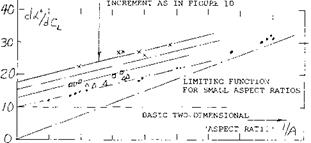
(doc °/dCL ) = (10/cos – A*) + (20/A) (18)

For А^= 25°, figure 11 confirms this function sufficient­ly well. However, the lift angles for Л = 50° are definitely higher than expected by equation 18. For the Л = 50° wing using equation (16) the right order of magnitude of dot°/dC_ is obtained. The mechanism of highly swept wings is thus believed to be different than that expected by the simple swept theory. The accumulation of bound­ary layer mentioned above can also be expected to be larger in higher aspect ratios (in long wing panels), while in smaller aspect ratios the distinction between swept and straight wings generally disappears; thus the boundary layer effects of swept wings must be considered.

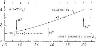
The lift angle increment believed to be attributed to viscosity based on experimental results is given in figure 10. This increment appears to be a function of l/cos2A,

(10) Influence of fuselage on lift of swept wings:

a) Pressure & Load Distributions, (7,b, c)(9,b).

b) West, Fuselage Location, NACA RM L1953B02 (21,e).

c) Johnson, Wing With Bodies, NACA RM L195 3J09a.

d) Schlichting, Influence, ARC RM 2582.

11) Diederich (NACA), analysis of lift f(A) and f(A):

a) Correlation on the Basis of “F”, TN 2335.

b) Spanwise Lift Distribution (Flaps), TN 2751.

(12) Wings with negative (forward) angles of sweep:

a) Hopkins, Half Wings A = 3 to 7, NACA TN 2284.

b) German ZWB Rpts FB 1411 and 1458 (1940)(8,b).

c) Junkers Ju-287, Jane’s A W Aircraft 1945/45; or Aircraft Fighting Powers, Vol 7 Harborough 1946.

d) McCormack, Stalling Swept-Forward, NACA TN 1797.

e) Whitcomb, at M = 0.6, NACA RM L1950K28 (5,d).

0 Purser, A = 3 With -45/+600 Sweep, NACA (9,e).

Thus, one way of describing the lift of highly swept wings is to add a constant increment in figure 11, which might be of the form

A(doc° IdCL ) = 1/cos2-A (19)

For -A*. = 50° the corresponding line in the graph aver­ages the experimental points.

EXPERIMENTAL RESULTS:

+ VARIOUS (5,c) (11,a) (12b, d)(12,b) x WINGS WITH 60° OF SWEEP (9,a)

& WINGS WITH NEGATIVE SWEEP (12,b) о HALF WING WALL MODELS (12,a)

A " 4 to 6
LIFT OF SWEPT WINGS

Figure 10. Increment of the lift angle caused by viscosity, as a function of the sweep parameter (l/cosA+. ).

wing, and at x/c^24% over most of the outboard two – thirds of the half span. In the words of (25,b) the “pres­sure peak line” determines the effective angle of sweep. The effective reduction of positive angles of sweep as in equations (20) and (35) is thus explained. To approximate the neutral angle as in figure 9 the line connecting the lh chord point of the root chord with the % point at the lateral wing edges is suggested to indicate the effective angle of sweep. This angle is illustrated in figure 5, where it happens to be 29° instead of 35°. In tapered wings, the difference as against the usual % chord definition is then found to correspond to

(Д-Л) = — (1/A)tan(l/1 + X ) (20)

For an assumed taper ratio A =0.5, the differential is Д-Л = —34°/A. For example, for A = 5, a A A^7° is indicated, which is not too much in comparison to what is evident in figure 9. We will identify the effective angle of sweep by the subscript (+), thus A + =A-A + A c/4 , and use this angle in equations (16) and (17). Thus equation 17 be­comes

(dor° /dQ_ ) = (10/cosA,.) + (20/A cos 7+) (21)

x FOR J = 50°

□ FOR, A+ = 40°

Л FOR J+ = 25°

о STRAIGHT WINGS
LIFT OF SWEPT WINGS

0 0,2 0,4 0.Q 0,8

Figure 11. The lift angle of swept wings (with larger aspect ratios) as a function of (1/A).

NEUTRAL ANGLE OF SWEEP. It is seen in figure 9 that the “zero” angle of sweep (where dCL /doc is highest) is shifted to – A/4 around +5° for A = 6. A corresponding shift by 5° is observed in Chapter VII of “Fluid Dynamic Drag” for the minimum of dC0 /dc£ . This is an empiri­cal fact. It can be said, however, that there is no cross flow at the center line of swept wings. The cosine prin­ciple applies in the outboard parts, say in the outboard two-thirds of the half spans. Shown for example in (26,c) and (26 Jh) the aerodynamic center of lift of the sections is around x/c = 40% in the center of a typical swept-back

INFLUENCE OF FUSELAGE. A convenient wind-tunnel technique is to attach half of the wing span (a half wing) to a wall or an end plate. Results are as follows:

a) As stated above, the lift-curve slope is reduced because of the boundary layer present and/or developing along the “wall”.

b) The flow pattern past the roots of swept-forward wings (as sketched in figure 8) seems to be improved, at least in comparison to that of swept-back wings, where the roots are rather disturbed.

Since fuselages do have a boundary layer, “wall” interfer­ence could reduce the lift-curve slope of swept-back wings. However, lift is generally increased and the “lift angle” decreased when testing in combination with a fuselage body. Shown in (7,c) the lift (in units of force per unit of span) carried by the fuselage is roughly the same as in the inboard Vi of the half-span of the 45° swept-back wing. This means that the dip of load as in figure 6, for example, is not present. In fact, there is possibly a pair of peaks induced by the fuselage on the wing roots (by way of the two-alpha principle, as ex­plained in Chapter III). Thus, the lift on and by the fuselage is larger than it would be in the center of the wing when tested alone. As a consequence, the total lift of the wing-body configuration is increased over that as indicated in the various illustrations.

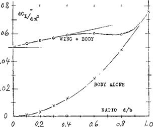
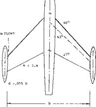
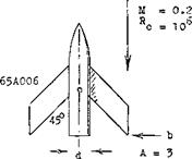
LIFT OF SWEPT WINGSThe influence of the body upon lift depends upon its size. As a function of the diameter ratio d/b, figure 12 shows how the combined lift L w& varies, resulting approxi­mately in

LWB/Lw = 1 + 0.5 (d/b) (22)

valid up to d/b = 0.4. References such as (9,b) confirm that lift is increased by the presence of a body in mid­wing position. As an interesting byproduct, the maximum lift coefficient (based on original wing area) is increased from C Lx = 0.9 to 1.8 when adding a fuselage with d/b = 0.4. Considering the high lift at d/b = 1, that is of the body alone, it should be realized that there would be in that graph a body with a length equal to 5 or 7 times the span of the original wing.

0
STRAIGHT RECTANGULAR, CHAPTER III

H STRAIGHT TAPERED, CHAPTER III

Я VARIOUS SWEPT WINGS. AS EVALUATED IN (11,a)

a SWEPT RECTANGULAR PANELS (9,f)

V SWEPT-BACK TAPERED WINGS (9,f)

+ RECTANGULAR SWEPT PANELS. AS FIGURE 9 Д SEVERAL SWEPT-BACK 60° WINGS AS IN(7,a)(9,f) x SWEPT-FORWARD TAPERED WINGS AS IN (8,b)(9.f) + SWEPT-FORWARD RECTANGULAR PANELS, AS IN (9,f)

1 Подпись:PLUS/MINUS SWEPT, AS FIGURE 9
LIFT OF SWEPT WINGS

LIFT OF SWEPT WINGS

Figure 12. The lift-curve slope (up to C L =0.8) of wing-body combinations (10,c) as a function of the diameter/span ratio.

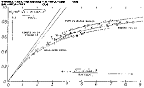
ASPECT RATIO. The function such as in equation (21) is no longer correct within the range of aspect ratios, say below 4. A very useful method describing the lift-curve slope of swept wings down to aspect ratios below unity is presented in (1 l, a). Defining the modified aspect ratio

F = A/а cosЛ* (23)

the lift-curve slope of swept and/or straight wings is indi­cated by the ratio

(dCL /doc )/(CL<fcCosAr) = F/(2 + vF + 4) (24)

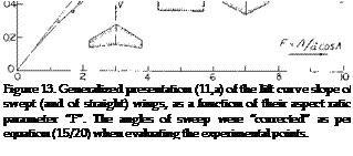
For conventional airfoil sections we can assume a = 0.9 and CLcC = (dCL/dod°2 ) = 0.1. Available experimental results have been evaluated on this basis and plotted in figure 13 in the form of

(dCL /doc )/(0.1 cosy+ ) = F/(2 Wf2 +4) (25)

Aspect ratios between zero and infinity are covered by this equation. The assumptions made in (11,a) permit presentation of a broad field of aspect ratios and sweep angles in one graph. Below F = 0.8 a limiting linear function is found. Combining equations (23) and (25) we obtain

dCL /d<x° = A/36 (26)

for “A” well below unity and for not too large angles of sweep. This equation is essentially the same function as that in the chapter dealing with “low-aspect-ratio wings”. The interesting result is that the influence of the angle of sweep simply disappears.

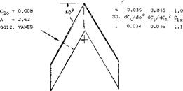
“CRANKED ” WINGS – M & W. Wings with a planform shape of an “M” or “W” are also called “cranked” wings (13,b). The idea for the use of these shapes was to delay or eliminate the pitch up moment encountered with swept wings, see Chapter XVI, and thus allow the use of higher values of sweep. Also, the same degree of sweep can be obtained with “M” or “W” without the need of extending the tips so far back. This was thought to have structural and aero-elastic advantages.

Подпись:LIFT OF SWEPT WINGSПодпись:Tests did show an advantage with the pitch up moment at angle near stall (13,f). The performance of the “M” and “W” planform wings was expected to be below that of the plane sweptback wing because of poor flow at the bends of the wing. The data of (12,b) does not confirm this as shown on figure 14. In fact, the performance of the “W” wing is slightly better than the equivalent 60° swept back wing, except near maximum lift. Although there appear to be advantages in the use of “M” or “W” wings, the practical design and construction problems have appar­ently eliminated their use.

R = Ю6 c

LIFT OF SWEPT WINGS

LIFT OF SWEPT WINGS

— Ъ – 4.3 ft

Figure 14. Characteristics of a 60° “cranked” or “W” wing in comparison to those of a plain swept wing (29,f).

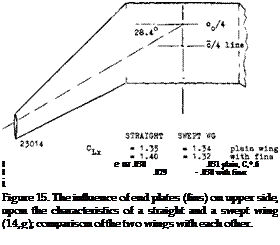
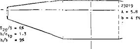
END PLATES. As presented in Chapter III any addition of end plates increases the lift-curve slope of straight wings. The maximum of (L/D) of swept wings is reduced, however, as shown in (14,g). The flow over the wing tips (prone to stall) is evidently made more difficult by the presence of end plates, after exceeding small lift coeffi­cients. Some drag and lift results are presented in figure 15. At CL = 0.6, total drag is somewhat reduced when adding the upper-surface fins. For a height ratio of h/b = 9% the reduction could be expected (see Chapter VII of “Fluid Dynamic Drag”) to be in the order of Л C0 = —.003, which is 10% of the total at CD = 0.6. Interference (not only in the swept, but in the straight wing as well) increases the viscous drag more than 30%. The maximum lift of either the straight or swept wings is only slightly effected by the use of end plates on the upper side. In (14,g) the end plates (on upper side) were also kanted, by 7.5° in and out, respectively. When kanted-in (toed-out, we would say) the flow pattern within the corner between wing surface and plates was slightly improved. When kant – ing outward, drag was increased. It thus shows that the weak flow over the wing tips cannot be improved appre­ciably.

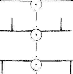
VERTICAL FINS. Vertical fins on top and/or below the wing can be used in tailless airplanes (using sweep-back) and will provide directional stability, Chapter XII. In the configuration as in figure 16, there is a small increase of

15-11

LIFT OF SWEPT WINGS

Figure 17. Influence of engine nacelles (16,c) upon the lifting characteristics of a swept wing.


dCj/dof


І

і


LIFT OF SWEPT WINGS

Figure 16. The influence of vertical fins added to a wing-body configuration (14,h) upon its lift.

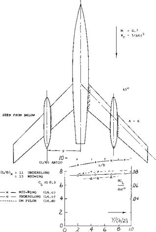
lift for end plates placed below the wing tips. From Chapter III the induced angle can be expected to be docL /dCL = [20/A (1 + 2/6)] = 3.3° , instead of 5.0° . For an angle of sweep – Л = 37 , the increment in the lift-curve slope should thus have been in the order of 9%. However, with the fins placed on top of the wing, there is no increment at all. Again, the tips of swept-back wings are found to be inefficient, and not susceptible to im­provement of the flow pattern.


0.06.6


0.066


0.067


LIFT OF SWEPT WINGS

ENGINE NACELLES. The pylons (struts) supporting jet engines below the wing (15) are in aerodynamic respect similar to end plates, moved inboard (say to Й half span). They might thus be expected somewhat to increase the lift-curve slope. Even engines without pylons, but under­slung (16), have an effect of this kind. As shown in figure 17, the lift-curve slope increases slightly when moving the nacelles toward the wing tips. The lift/drag ratio is, of course, higher with the nacelles in midwing position then when located inboard (less frontal area). Also, the maxi­mum of that ratio (at CL^0.3) increases noticeably when moving the nacelles outboard.

(15) NACA, external stores on Douglas D-558-II:

a) Silvers, Various Shapes Subsonic, RM L.1955D11.

b) Kelly, In 2 Spanwise Locations, RM L1955107.

c) Smith, Characteristics at M = 2, RM L1954F02.

(16) Engine nacelles on swept wings:

a) Pressure Distribution, ZWB UM 3176, NACA TM 1226.

b) Boltz, Pressures and Forces, NACA RM A1950E09.

c) Silvers, Spanwise Position, NACA RM ІЛ953НГ7.

d) Pearson, At Transonic Speeds, NACA RM L1957G17.

e) Hieser, Sweep and Fences, NACA TN 1709.

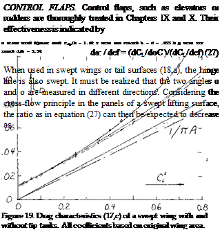
TIP TANKS – SWEPT WINGS. Wing tip tanks are used on swept wings for the same reasons as were discussed for straight wings in Chapter III. Also, the general flow and interference characteristics encountered are similar. The relative performance (17,c) of a swept wing with and without tip tanks is shown on figures 18 and 19 and includes data with end plates of a comparative height. As shown on figure 18, the lift curve slope increases from.054 for the wing with square tips to .063 with tip tanks. This increase is even larger than for the wing with end plates of a similar height. The data plotted on figure 18 is all referred to coefficients based on the original wing area. However, if the lift angle and slope are adjusted for the change in area and aspect ratio, the end plate effect of tip tanks agrees with corresponding data for end plates.

In comparing the drag as measured in (17,c) the use of tip tanks does not show any improvement over the original sharp tip wing, figure 18. This result cannot be general­ized, however. In the configuration as tested, there was a

LIFT OF SWEPT WINGS

Figure 18. Lift characteristics (17,c) of a swept wing with and without tip tanks. All coefficients based on original wing area.

/

x*

/

LIFT OF SWEPT WINGS
LIFT OF SWEPT WINGS

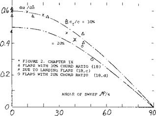
doc /dd — cos A (28)

The scattering results in figure 20 seem to confirm this reduction. An inspection of the effectiveness of outboard ailerons (19) shows that their roll moments reduce at a rate even stronger than in proportion to cos A. The same deterioration is also found in swept-forward wings (19,a).

(17) c) Salter and Jones (NPL), Swept Wing with End Plates in CAT, ARC Current Paper 196(1954).

d) Hartlet, Tip-Tank analysis, ARC CP 147.

e) RAE, On Swept-Back Wing, ARC RM 2951.

f) Weber, Analysis Wing & Body, ARC RM 2889.

g) NACA Tunnel Tests, RM A5F02, A5G02, L9J04.

(18) Effectiveness of Swept trailing-edge flaps:

a) Dods, Horizontal Tails, NACA TN 3497.

b) Harper, Tail Surfaces, NACA TN 2495.

c) Small Chord Ratios, NACA TN 2169 and RM L8H20.

d) Young, Wing Flaps, ARC RM 2622.

Ц9) Effectiveness of ailerons on swept wings:

a) Luoma, Ailerons on Wings, NACA L1947115.

b) Bennett, Roll Moments Swept Wings, NACA TN 1278.

LIFT OF SWEPT WINGS

Figure 20. Lifting effectiveness of full-span wing – and/or control – surface flaps, as a function of their angle of sweep.

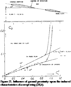
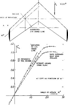
GROUND EFFECT: Ground effect, that is the influence of ground proximity when taking off or landing, upon the lift of straight wings, is presented in Chapter XX In the case of swept wings, it can be visualized that the tips of a wing with 60 sweep, for example, would eventually touch the ground, while the apex is still high in the air. Lift and drag of a 40° swept wing are plotted in figure 21. Around zero lift the induced angle ratio (for CL = constant) is approximately (dod L 3 /doc u ^ )

= 0.54 evaluated from lift

= 0.63 corresponding to drag.

These values are smaller than those in figure 28 of Chapter III, for h/b = 0.18, measured to % of the mean chord. As discussed in that chapter, reasonable agreement can be found when defining the ground distance to the % point of the mean chord. This would also straighten out the CL (od ) function. However, above CL = 0.7 a deficiency of lift is seen to exist in the presence of the ground. The cause is stated in (20,b) to be “intermittent stalling” along the trailing edges (outboard). — The ground effect is, of course, of particular interest when landing an airplane; and that is usually done with the wing flaps extended. Deflected flaps are aerodynamically equivalent to an in­crease of the angle of attack. As found in (20,b) the same reduction of the induced angle is obtained as in figure 21. Stalling begins, however, at the same lift coefficient as without flaps. Subsequently, the drag due to lift increases progressively with the lift coefficient. The flapped center portion of the wing eventually stalls, resulting in a maxi­mum lift coefficient reduced from 1.41 (in free flow) to 1.24 (near the ground).

v20) Influence of ground on lifting swept wings:

a) Thomas, Theory/Experiment, Ybk WGL 1958 p 53.

b) Furlong, Experimental, NACA TN 2487 or Rpt 1218.

c) Hafer, Z FlugWissenschaften 1958 p 20.

d) Wyatt, On “M” Wing, ARC C’Paper 541.

e) LIFT OF SWEPT WINGSПодпись:Wood, Effect on “Swift Model, ARC C’Paper 458.
LIFT OF SWEPT WINGS

Possibly the most dramatic single development in the aerodynamic design of aircraft is the invention, the exploration and the practical application of the swept wing, first in high-speed-comb at (1947) and then in com­mercial transport airplanes (1952). In this first chapter dealing with sweep, characteristics of wings are presented as follows: principles of swept wings, the lift of swept wings, influence of compressibility on lift. Some of the characteristics of wings already discussed in other chapters are found to be more complicated for swept wings.

usually defined as that of the quarter-chord line. As we will see later, this is one of the fallacies of theoretical aerodynamics, however. In figure 1, we have used the Vi chord line for the definition of sweep. It is interesting to note that when looking at a swept plan form, particularly as in part (c) of the illustration, one tends to overestimate its aspect ratio. The eye evidently sees the elongation of the two panels, and the “aspect ratio” of the panels is obviously what the structural engineer has to cope with.

1. PRINCIPLES OF SWEPT-WING FLOW

Swept wings have specifically been developed to increase the critical Mach number. Thus, higher cruise speeds are possible without encountering a high drag rise due to high operating Mach numbers. Further, since the critical Mach number decreases with increasing section thickness ratio and camber the effects of increasing these parameters, say for structural reasons, can be compensated for with an increase of the sweep angle.

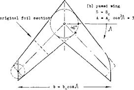
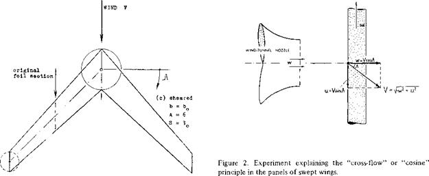
GEOMETRY. The elements of swept wings are the wing panels. As shown in figure 1 the simplest way of “pro­ducing” a swept wing is by sweeping (yawing) the two panels (as in variable-sweep airplanes). The wing sections are thus kept constant constant normal to each panel axis. The span and aspect ratio of such wings are reduced in the process:

b = bQ cosyt ; A = A0cosy (1)

where the subscript “o” refers to the unswept wing.

The tips of a “yawed” swept wing are usually modified to a “sheared” form, as shown in figure l, b. In reports such as (1) or (26,c, h) a leading edge curving back near the wing tips has been developed in England, evidently ac­commodating the trailing vortices which cannot very well be suppressed; see figure l, b. The angle of sweep Л is

LIFT OF SWEPT WINGS

LIFT OF SWEPT WINGS

Figure 1. Geometry of swept wings; example of a tapered wing with Асд= 6, swept to Ac/4 =45°.

(1) Bagley, “Aerodynamic Principles of Swept Wings”, Vol 3 “Progress in Aeron Sciences”, Pergamon 1962.

SHEARED WING. A sheared wing is produced by moving (on paper) the wing sections parallel to one another in flow or flight direction until the desired angle of sweep is obtained. Since span and aspect ratio remain constant in this case, and the wing tips retain their lateral edges (as they are usually designed for airplanes) this definition seems to be preferable in analysis and discussion. It should be indicated, however, whether the foil sections are de­fined in the direction of flow (sheared) or normal to edges or axes of the wing panels (yawed). The thickness ratio is:

(t/c)v = (t/c)n cos J (2)

where V indicates the direction of flow or flight, and “n” that of the component w, that is “normal” to the edges or axes of the wing panels.

(w = V cos Л ) and (u = V sinA ) (4)

As long as skin friction is of little or no importance, (2,d) the u component does not have an influence upon the pressure forces (drag, lift, pitching moment, wing-flaps, compressibility) produced by the component w. In other words, we could calculate and/or measure for example lift:

L= CLaorn S(0.5 ^ w2 ) (5)

where C uo( = lift-curve slope in two-dimensional flow would be a constant characteristic of the airfoil section, such as (0.9 2 к ) — 0.01 , and defined in the direc­tion of w that is normal to the edges of the wing. Refer­ring this result to direction and magnitude of the “total” speed V, the dynamic pressure has to be modified corre­sponding to

(0.5 p wz )/q = (w/V)2 = cos A (6)

LIFT OF SWEPT WINGS

Figure la. Geometry of swept wings: cont.


CROSS-FLOW PRINCIPLE. To understand the aero­dynamic mechanism of sweep, we will consider a long and narrow piece of wing, similar to that in figure 2, moving across a stream of air ejected from the nozzle of an open-type wind tunnel. Evidently, the wing is subjected to the velocity w. However, since the wing itself is moving sideways with the velocity u, the resultant speed of air against the wing is the geometrical sum

V = Vw2 +u2 (3)

To say it in different words, the speed “V” (of a swept – wing airplane) can be split up into the components

In the new system, which corresponds to a straight wing flying at an angle of yaw (sideslipping), the angle of attack measured in the direction of V is reduced to

cos A (7)

In two-dimensional flow the lift is then

L = c L or s( «"n / °0 t(°-5 p w2 )/q] q (8)

and the coefficient, with subscript “2”, is for condition in the direction of flight

(2) Lift of airfoil sections in oblique flow:

a) Lippisch, Pressures in Oblique Flow, ZWB FB 1669 (1942), NACA TM 1115; also Koch ZWB UM 3006.

b) Dannenberg, Pressure Distribution, NACA TN 2160.

c) Watkins, Streamline Pattern, NACA TN 1231 (1947).

d) Cross-flow principle, III & XV of “Fluid Dyn Drag”.

C|_2 = ^La (tfp/cos-A )cos2A = CLcy<yz cosA

(9)

In other words, the lift-curve slope is (dCL /dec )2 =

(C L0C cos a) ; and the lift is L^cos A, for oc – constant in the direction of flow or flight.

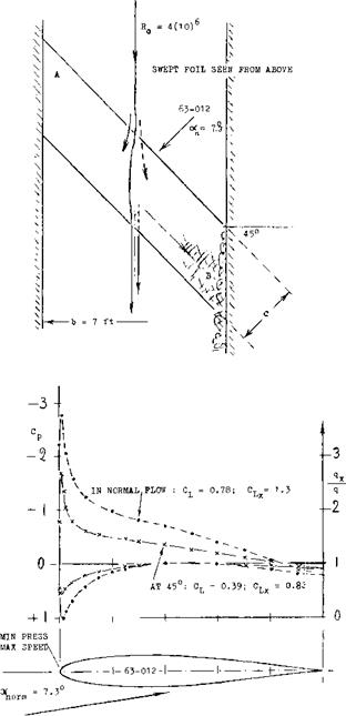
YAWED AIRFOIL. Experimental results of a wing obliquely spanning the closed test section of a wind tun­nel at an angle of 45 degrees are presented in figure 3.

LIFT OF SWEPT WINGS

Figure 3. Flow pattern and pressure distribution of an airfoil, tested (2,c) between tunnel walls, at an angle of yaw or sweep Ac/4 = 45°. The angle of attack is defined in the direction normal to the geometric span (axis) of the wings tested.

Note that the panel is of the “yawed” type, and that c = constant (measured in the direction normal to the edges). The flow is essentially two-dimensional. As tested at half-span, pressure and lift coefficients are reduced in comparison to the same airfoil at Л = 0, in proportion to cos2y = 0.5; thus for a normal flow lift coefficient of 0.78 the effective value is: CL = 0.5 (0.78) = 0.39. It should be noted that the dashed line on figure 3 is drawn to Vi scale of the solid line, yet meeting most of the test points. However, if the angle of attack has been kept constant in the direction of flow (parallel to the tunnel walls) the lift and dC L /doc will be proportional to cos Л = 0.71, thus confirming equation (9). Based on the data presented in figure 3 the following observations are made:

a) Because of the presence of the tunnel walls the cross flow is not correct at both ends of the airfoil.

b) The forward end of the foil evidently pushes down some volume of air. A corresponding upwash (circulation across the stream) is thus induced ahea^ of the down­stream area of the wing. As a consequence, lift in this end is some 10% higher, and in the upstream end 10% lower than in the center.

c) The boundary layer flows (at the higher lift co­efficients) from the upstream end of the wing, picking up on its way roughly parallel to the trailing edge, finally arriving at the downstream end of the airfoil.

d) As a consequence of (b) and (c) stalling (separation) takes place first at the sweptback on downstream end. Maximum lift in the center sections of the two airfoils is reached approximately at the same angle ot, defined in tunnel direction. The coefficient is reduced, however, from CLx = 1.30, as in the airfoil at Л = 0, to 0.83. This value of C|_x is some 10% less than C Lx cos A = (1.3).71 = .923 which is the theoretical expectation.

e) If the downwind end of the wing fully produced the lift corresponding to the upwash stated under (b), the flow would be two-dimensional. Because of the boundary layer transport under (c), lift is deficient on the downwind side thus leading to part-stalling as under (d). As a conse­quence, the stream tube splitting “at”, the leading edge does not recombine past the trailing edge. This means that a certain rotation and/or circulation (a vortex) is left behind in the tunnel stream. This transfer of momentum results in an induced drag loss.

f) At CL =0 the wake-measured minimum drag co­efficient is CD = 0.0041 for either of the two laminar – type airfoils tested. The CL size of the laminar “bucket” is reduced, however, by sweep, possibly in proportion to cos A. At су = 6 (in the direction of tunnel flow) C D = 0.0007 for either of the two angles of yaw tested; the lift coefficients are different, however.

Qualitatively, all components of the flow pattern proper­ties discussed above are found in real swept wings!

DIRECTION OF FLOW. In spite of the cosine principle of “cross” flow, the average direction of the flow of air past the upper and lower sides of any swept wing is essentially that of the undisturbed outside flow. As a consequence, the Reynolds number (basically responsible for the development of the boundary layer) is properly defined using the average wing chord measured in that direction and the undisturbed velocity of flow or flight (3). It should also be noted that wing attachments such as engines, pylons supporting them, all kinds of fairings and the rails (tracks) supporting Fowler-type or multiple – slotted wing flaps, and finally fences (see later) are usually arranged in the same direction.

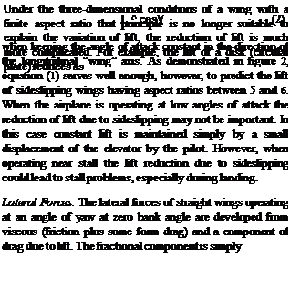
SIDESLIPPING. At an angle of yaw /3 , or when sideslipping, the lift of a straight wing changes in proportion to the effective dynamic pressure as in equation (6), and its sectional “lift angle” measured normal to the wing edges, increases accordingly. The induced angle is based on the wing span which is reduced in the direction of flow or flight in proportion to cos p. Consequently, (dop/dCL ) ^1/cos2# (where <yL is defined in the direction of flight), or (docni_ /dCL ) ~ l/cosz/3. Using the formulation as in Chapter II, the total angle (normal to the wing edges) is then approximately:

The fact that experimental results plotted in figure 4 more or less follow a simple cos2/3 function suggests that the first term in the equation deteriorates as a consequence of the boundary layer flow as stated under (c) above. It is seen, however, that an elliptical wing and one with zero taper ratio follow equation (10). In the case of a rec­tangular wing there is a secondary effect involved. When turning such a wing into an oblique flow, the span (meas­ured between diagonally opposed corners) increases to a certain limit, particularly in small aspect ratios. As a consequence, the induced component of their lift angle may not increase within some range of the angle of yaw, such as 19°, for example, for A = 3. Our interest is, however, not in plain wings flying at an angle of yaw, and this may not be the best way of considering swept wings.

THEORY – DYNAMIC LATERAL STABILITY

The theory for determining the dynamic stability charac­teristics of airplanes is relatively complex and lengthy, especially with all six equations of motion. The complete development of these equations and their analysis has been done by several authors (13,a, c,d) specializing on the subject of stability and control, and will not be repeated here. We will provide sufficient information for develop­ing a basic understanding of the problem and show the important relationship of some of the stability derivatives. In the following section variations of the forces and mo­ments leading to the stability dynamic derivatives will then be covered.

Basic Equations. In developing the equations of motion for an airplane certain simplifying assumptions are usually made. These are:

a) Second order terms are neglected — the disturbances are small.

b) The motion is steady about the symmetrical plane. The six equations of motion can be broken up into the longitudinal and lateral modes.

c) The changes in lift and moments due to changes in motion are instantaneous.

d) The controls are fixed.

(*Cnp>,

(ACnp)2

(^CDo)(* D°*(30)

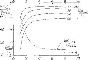
Подпись:Подпись: A + 2 cosA ^ 2 J— .125 (CD -CL ТГА) A + 4 cosА/

Подпись: The effects of free controls, stick free case, are covered in (13,a,c) and involve many more degrees of freedom in-cluding the hinge moment variations of the control surface. From (13 ,b) the equations of motion based on these assumptions are as follows — referred to the airplane stability axis:
Подпись: the wing and tail geometry, the lift and the drag. The contribution of the wing can be estimated from the equa-tion (30) and figure 20 taken from (13,d).
Подпись: C
Подпись: np

Roll

2ді (Кх2 Db20 + Kxz D2yO =

d d (271

+ 1/2 Cf p Db/ef+l/2(y D/

Yaw

2pb(K2 +KxZDb 0) =

Cn^’+1/2CnpD/+l/2CnrDb^ (28)

Sideslip

2^b(Db^+Db^) = Cyfi/9+ l/2CypDb/af+CL. Jzf+ l/2CyrDbi/’ + (CLtany)/’

Where /кб-=

airplane relative density factor = (m/PSb) some authors use b’ for the wing semi span instead of b.

к* =

nondimensional radius of gyration in roll about longitudinal axis.

nondimensional radius of gyration in yaw about the vertical stability axis.

Db =

differential operator (d/dsb)

On the right hand side of the above equation the aerodynamic characteristics of the airplane are given while the moment of inertia, prodiict of inertia and acceleration are given on the left side.

Rolling Derivatives. In equations 27, 28 and 29 CW/c), Cj£p and Cyyo the derivatives due to the rolling velocity are encountered. These rolling derivatives are taken with re­spect to the effective helix angle of the wing and thus depend on both the forward and rolling velocity. The yawing moment due to roll is mainly determined by [128]

The vertical tail configuration to Cnpis found from the equation

C77(Bi=-(2i/bXz/b)Cy^ (31)

where Cygj – is determined considering the sidewash and effective tail length data of Chapter XIII.

THEORY - DYNAMIC LATERAL STABILITY

Figure 20. Variation with aspect ratio and sweep angle of compo­nents required to find CL^with equation 30, from (13,d).

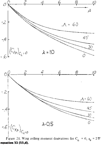
Damping in Roll The rolling moment due to rolling, C is mainly a function of the wing, sweep angle, taper ratio, and operating CL . Based on the method and data given in (13,d) which appears to be accurate and well accepted the Cjip can be calculated from equation 32 using the data of figure 21 to find Cat = 0. Equation 32 is then used to find the value of at the operating lift coefficient

C,

(CLaf)c L CL

(9?p)c|=o (C ) 8 Acos^t

^1 + 2 sin9

(32)

The slope of the lift curve for the wing CLa^ at CL =0 and the operating CL is found using the data given in Chapters II and III. The effect of high lift flaps on the damping in roll of the wing are accounted for by using the proper slope of the lift curve corresponding for these devices as determined from the data of Chapters V and VI. If the wing has tip tanks, corrections as presented in (13,d) must be applied to the calculated value of

Подпись: equation 32 (13,d). Yawing Derivatives. The derivatives of the yaw and rolling moments and the side force with the yawing motion, Cnr С*, and Cyr also appear in the equations of motion (27, 28 and 29). The damping in yaw derivative, Cnr is not greatly affected by the fuselage and wing as the velocity change due to yaw is relatively low. The vertical tail has a larger effect as it presents its flat surface to the motion. At moderate angles of attack the value of Cnr due to the vertical tail may be found from the equation
С-ЯТtai|_2(-£/b) Cy^ toil (35)

The side force derivative Cy^ is obtained from the data of Chapter XIII.

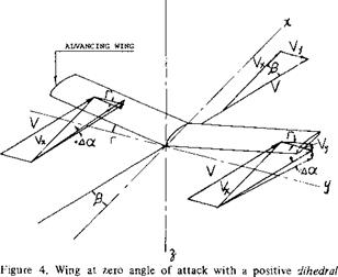
The rolling moment due to yaw, C^, is mainly effected by the wing and vertical tail. This occurs due to the angular velocity of the wings which cause an increase in lift on the advancing wing and a corresponding lift de­crease on the retreating wing. These changes in lift result in a rolling moment which can be estimated for straight wings from equation (36) developed from the data of (13,d).

CL (.04A + .24) (36)

The effect of the vertical tail is estimated from the equa­tion

C^ = -2(-*/b)C^to|1 (37)

THEORY - DYNAMIC LATERAL STABILITY

The contribution of the horizontal and vertical tail to C^, can be estimated in a similar manner to the wing, how­ever, the value is usually small and is neglected.

Lateral Force Due to Rolling. For a wing operating at conditions where the drag due to separation is low the derivative Cy/?, lateral force due to rolling, can be deter­mined from equation 33.

Cy/> = Q_ [(A + cosA)/(A + 4 cosjY)] tanA+l/A (33)

The value of Cy/o at high lift coefficients from test data is lower than would be calculated from equation (33). At these conditions test data should be used if possible to find the lateral force derivative due to rolling. The lateral force derivative due to the vertical tail can also be esti­mated using equation (34). The side force derivative for the tail used in equation 34 is obtained from the data of Chapter XIII.

C yp tail =2(Z/b)Cyrai, (34)

The procedures for estimating the rolling derivatives given above apply only in the subsonic speed range.

In the case of the side force derivative due to yaw the theory appears to be inadequate so that experimental data should be used. The effect of the vertical tail however can be found from equation

Cy^ =-2i/b Cy/Itaii (38)

Dynamic Stability. The linear differential equations (27, 28 and 29) with constant coefficients are solved in the usual manner for these types, assuming that the following substitutions can be made:

j0o ew = jar, ^елт = , a =£

With these substitutions a characteristic equation for is obtained.

AA?+B A3+CXa + DX+E = 0 (39)

Where А, В, C, D and E are functions of the aerodynamic and mass properties of the airplane which in turn depend on the steady state flight conditions. It is shown in (13,a) there are four different types of motion depending on the roots of the characteristic equation (39).

1) When X is real and positive the motion increases steadily with time and the aircraft is unstable.

2) If X is real and negative the airplane is dynamically stable.

3) With complex root containing a negative real part, the motion is a damped oscillation tending toward zero.

4) When X is complex with a real part positive an increas­ing oscillation motion is obtained tending toward in­finity, unstable.

Also when X is zero the motion persists undamped and if is complex with a zero real part, simple harmonic motion is obtained.

Подпись:Подпись:Подпись:

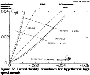
Подпись: These stability boundary are useful for evaluating the stability of an airplane configuration and are illustrated on figure 22 in terms of vs . When the airplane passes through the upper boundary, one of the real roots becomes positive indicating the airplane is unstable. This is known as spiral instability.
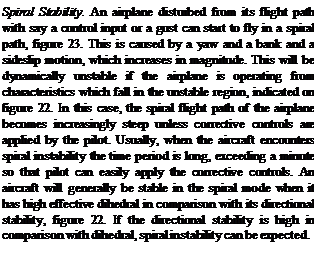
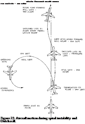
Подпись: Spiral Stability. An airplane disturbed from its flight path with say a control input or a gust can start to fly in a spiral path, figure 23. This is caused by a yaw and a bank and a sideslip motion, which increases in magnitude. This will be dynamically unstable if the airplane is operating from characteristics which fall in the unstable region, indicated on figure 22. In this case, the spiral flight path of the airplane becomes increasingly steep unless corrective controls are applied by the pilot. Usually, when the aircraft encounters spiral instability the time period is long, exceeding a minute so that pilot can easily apply the corrective controls. An aircraft will generally be stable in the spiral mode when it has high effective dihedral in comparison with its directional stability, figure 22. If the directional stability is high in comparison with dihedral, spiral instability can be expected.
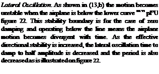
Подпись: Lateral Oscillation. As shown in (13,b) the motion be-comes unstable when the airplane is below the lower curve on vs pl°U figure 22. This stability boundary is for the case of zero damping and operating below the line means the airplane motion becomes divergent with time. As the effective directional stability is increased, the lateral oscillation time to damp to half amplitude is decreased and the period is also decreased as is illustrated on figure 22.

Based on the analysis of equation (39) to determine the characteristics of its roots presented in (13,b, d) stability boundary conditions can be set up for any airplane and operating conditions.

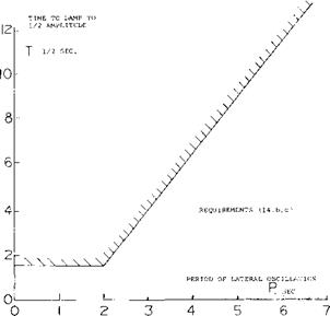
Some of the earlier specifications (14,b, c) relating to the desired flying qualities of an airplane used a criteria for time to damp to half amplitude as a function of the period of oscillation. This criteria, illustrated on figure 24, has been found to be unsuitable for elevating high per­formance aircraft as it does not adequately consider the pilots requirements. It has been found necessary to rely on pilots opinion to establish the proper damping ratio because of the complex inter-relationship between the airplane dynamics and the control function. Also, when operating with positive damping the lateral oscillation couples with a yaw oscillation and a sideslip, which gives a motion after a disturbance known as “Dutch” roll.

THEORY - DYNAMIC LATERAL STABILITY

• і

Figure 24. Desired damping characteristics as a function of period of lateral oscillation (14,b, c).

“Dutch” Roll. The “Dutch” roll characteristic of an air­plane has become an important design consideration, es­pecially with high performance and STOL aircraft. The “Dutch” roll is characterized by a rolling, sideslipping and yawing motion where the frequency about both axis is of the same order of magnitude but they are slightly out of phase. Thus, if we have a rolling motion as in figure 23, say to the right, with a corresponding sideslipping right yaw followed with a left roll and yaw where the yaw motion follows the roll, the airplane is in the “Dutch” roll mode. The frequency of the motion is much higher than for the spiral stability case. When the effective dihedral is very high in comparison to the directional stability the lateral-directional oscillation may actually become dy­namically unstable and increase in amplitude.

Thus, in comparing the requirement for good “Dutch” roll characteristics with spiral stability a variance is noted between the need for high effective dihedral and direc­tional stability.

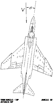
Lateral Directional Stability – High Angles. Due to the stalling characteristics of swept wings, fuselage flow inter­action on the tail, there have been many problems with lateral-directional stability when operating at high angles of attack. An example of the unfavorable characteristics of a jet fighter type airplane at high angles is given in (15,a). This airplane, figure 25, encountered directional divergence brought about by a simultaneous loss of direc­tional stability and effective dihedral when operating at high angles of attack. This loss of directional and lateral stability is a part of one cycle of a highly unstable “Dutch” roll oscillation. The loss of the stability is caused by stalling of the leading wing panel at high angles and the adverse sidewash as illustrated in figure 25.

The “Dutch” roll instability time to damp to half ampli­tude, t1/2, and the period of oscillation, P, can be pre­dicted based on theoretical methods (15,a) from the equa­tions

P = 2 /d (b/v) (40)

T = -.693/c (b/v) (41)

Where c and d are the real and the imaginary parts of the root of the characteristic equation. When the quantity 1 /ti/2 becomes negative the airplane becomes dynami­cally unstable as illustrated in figure 24. To accurately find the roots of the characteristic equation and thus find the resultant instability it is necessary to find the many derivatives of the airplane as a function of angle of attack. At high angles of attack where separation of the flow is encountered it is necessary to use wind tunnel test data to find the derivatives and thus evaluate the stability. And here Re and M and roughness are subject to scale effects.

(15) Complete Airplanes:

(a) Chambers and Anglin, Lateral-Directional Stability of a Fighter Airplane, NASA TN D-5361.

(b) Heinle, Lateral Oscillation Several Aircraft, NACA RM A52J06.

(c) Campbell & McKinney, Aircraft with Satisfactory Dutch Roll Oscillation, NACA TR 1199.

(d) Ray, Large Sideslip Angles – T-Tail Transport, NASA TM X-1665.

(16) Lateral-Directional Handling Qualities:

(a) Ashkenas & McRuer, Handling Qualities from Pilot – Vehicle Considerations, Aerospace Engineering, Feb. 1962.

(b) Ashkenas, Lateral-Directional Handling Qualities, US AFFDL-TR-65-138, Part II, Nov. 1965.

(c) Miller & Franklin, Lateral-Directional Flying Qualities for Power Approach, J. Aircraft Vol 5. No. 2 1968.

(d) Vomaske, Sadoff and Drinkwater, Lateral-Directional Couplings — Fixed-Base Simulator, NASA TN D-1141.

(e) Teper, Lateral-Directional Handling Qualities, J. Aircraft May, June 1966.

Подпись:STALL TAKES PLACE ON LEADING WING PANEL AND CAUSES A LOSS OF EFFECTIVE DIHEDRAL.
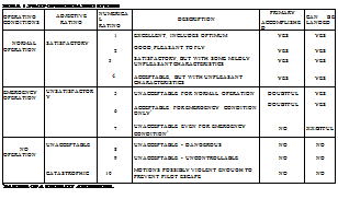
BEHIND STALL, FLOW IS REVERSED CAUSING A LOSS OF TAIL EFFEC­TIVENESS AT HIGH ANGLES OF ATTACK.

Figure 25. High performance fighter aircraft at a high angle of attack and yaw angle.

4. LATERAL DIRECTIONAL FLYING QUALITIES

The basic flying qualities of an airplane must be satisfac­tory throughout the operating range especially with high performance STOL and fighter type airplanes. Operating problems at the low speed landing condition and at high altitudes are caused by low damping conditions when operating at high lift coefficients. In cruising flight prob­lems are encountered due to low damping which are a direct function of the geometric characteristics of the airplane. These problems have often led to the use of artificial mechanical stability augmentation systems (SAS). Although it is desirable to design the airplane to have the desired basic stability this is not always possible, so that SAS systems become a requirement. In fact, most modern high performance swept wing aircraft use SAS systems to obtain the desired level of stability and so reduce the work load of the pilot.

Pilot Ratings. Because of the opposite requirements of the levels required of effective dihedral, C^ , and directional stability, СП£ , it is necessary to use pilot ratings to establish the best configuration and the gains needed in the SAS system. Pilot ratings based on the Cooper ten point rating system (17,a) are very effective and consis­tent for evaluating a configuration. As noted on table 1, the Cooper rating system judges a configuration in terms of the ease of flying the airplane. A rating of 1 is the best and 10 the worst. Cooper ratings are obtained by the operation of flight simulators, variable stability test air­planes or the actual airplane being evaluated (17). The degree of correlation of the ratings between the various methods depends on the level of simulation used and are usually quite consistent in trend. To provide the data for evaluating new designs the pilot ratings must be related to the aerodynamic characteristics of the airplane as dis­cussed in (16,b).

Подпись:Aircraft Handling Qualities. Investigations have been made to determine the characteristics of the control system and the inherent stability to obtain high pilot ratings. These investigations (16) have been made to determine the spe­cific parameters best suited, such as roll damping and roll acceleration for correlation with pilot ratings. Such corre­lations are incorporated into aircraft design specifications that the designer must meet. If the constraints of the configuration or its operation are limiting in achieving the desired stability it may be necessary to obtain the needed characteristics with a SAS system. SAS systems have been used on many high performance aircraft, including most STOL and VTOL types. Any information available which relates Cooper rating to period, tor stability deriva­tive combination would be very useful.
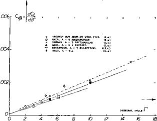
Подпись: (18) Stability Augmentation System: (a) Montgomery, Differential Synthesis to Design, J of Aircraft, July, Aug 1969.

INFLUENCE OF FUSELAGE ON ROLLING MOMENT

Although conventional fuselage shapes do not produce a significant rolling moment, their interference effects upon the wing moments are large and cannot be disregarded. Such effects are particularly evident in regard to the rolling moment when sideslipping.

(11) Analysis of rolling moments due to fuselage:

(a) Jacobs, Analysis, YearbkP Lufo 1941 p 1-165.

(b) Braun, Rotational Body, Ybk D Lufo 1942 p 1-246.

(c) Maruhn, Rectangular Shapes, Ybk D Lufo 1942 p 1-263.

Analysis. Evaluation of the two-dimensional cross flow field as in (11 ,a) of a fuselage with an equivalent infinitely long cylinder then yields a flow-angle distribution along the lateral axis (beam) and a corresponding lift distribu­tion. The resultant rolling moment is essentially independ­ent of the wing’s lift coefficient and is a function of the geometry of the wing-fuselage combination. As an exam­ple, numerical results for a specific configuration taken from (12,a) are given in figure 19. Experimental results confirm the theoretical prediction with reasonable accu­racy. In the two extreme positions, at h/r = plus and minus 1.0, the rolling moment derivative produced by the fuselage is the equivalent of plus/minus 3.5 dihedral, i. e. for the configurations as tested having b/d in the order of

8.

Fuselage/Wing Size. The influence of the fuselage de­scribed above was analytically studied (11 ,a) for a number of configurations with the following results:

1) The effect of a body with Л/d = 7 is up to 10% smaller than that of a long cylinder.

2) The influence of wing shape (rectangular or elliptical) is small.

3) The rolling moment is for practical purposes independ­ent of the wing’s aspect ratio, meaning that the incre­ment of the coefficient ДС^ ~ 1 />Га for constant wing area.

4) The increment of the rolling-moment coefficient deriv­ative is proportional to (d/b)2 and it reduces in pro­portion to 1/b for a given fuselage. The moment is proportional to (d2 c) where c = average wing chord; therefore, “L”/(q d2 c) = constant for a given body shape.

Shape of Fuselage. Various cross-sectional shapes (circu­lar, elliptical, square, rectangular) have analytically been investigated (11). For practical purposes, it can be de­duced from the results:

a) A square fuselage shape (with rounded edges) has approximately the same effect as a circular shape (as in figure 19) provided that the fuselage volume (rather than the d/b ratio) is kept constant.

b) In the case of fuselages with elliptical or rectangular cross-section shapes the rolling moment induced by them increases approximately in proportion to the height/width ratio, again provided that volume or cross-sectional area is kept constant. [127]

Dihedral. As noted above, the effect of the fuselage upon rolling moment is the equivalent of a certain wing di­hedral. It is also stated that the derivative of the coeffi­cient (indicating rolling moment in relation to wing lift) varies in proportion to (d/b) . Any small-span (small – aspect ratio) and high-wing airplane configuration is there­fore liable to have too much rolling moment due to yaw. An example of such a configuration is the Lockheed F-104 high-speed fighter airplane. Rolling moments are reduced by giving the wing a few degrees of negative dihedral. All low-wing airplanes have, on the other hand, appreciable amounts of positive dihedral (between 5 and 10°), (a) to counter-act the “negative” effect of their fuselage and (b) to provide the magnitude of rolling mo­ment desirable for optimum handling and for lateral sta­bility.

Influence of Wing Flaps. Conventional landing flaps are of the part-span and inboard type. They may also be used (at a moderate angle of deflection) during take-off and while climbing. Their influence upon the characteristics of wings is basically similar to that of tapered plan form and/or wing twist.

LATERAL CHARACTERISTICS DUE TO DIHEDRAL

Dihedral of “V” shape has a considerable influence upon forces and moments of sideslipping wings.

Lift Differentials. When placing a dihedraled or “V” shaped wing at an angle of yaw, the angle of attack (against the flow) of the forward panel is geometrically increased; and that of the trailing panel is reduced figure

4. The differential of the angle of attack is

доС = ±АГ (8)

where Г = angle of dihedral. The differential of the lift coefficient in each panel, corresponding to that of the angle of attack, is

A CL =*рГ dCt /doc (9)

When considering a wing with an antisymmetrical varia­tion of the angle of attack, the lift-curve slope to be used in equation (9) corresponds to half the aspect ratio of the wing. Following procedures as given in Chapter III, the “lift angle” to be used in equation (9) is then:

doL° /dCL ~ 10 + (19/0.5 A) (10)

Lateral Force. The lateral force due to dihedral is simply the sum of the spanwise components of the lift differen­tials in the two wing panels:

Cy<1 =+£Гг dCt /doc (11)

For example, for A = 5 the “lift angle” is do( /dCu = 17 . Measuring all angles in degrees, the lateral force derivative for dihedraled wings with A = 5 is thus expec­ted to be

dCyj. /dp° = + (7Г/180)* Г 2 /17 =

+ 1.8 Г*І5 (12)

Experimental results for model wings with A = 5 and 6, as plotted in figure 8, confirm the equation.

LATERAL CHARACTERISTICS DUE TO DIHEDRAL

Figure 8. Lateral force derivative of various wings having aspect ratios in the order of 5 and 6, as a function of the dihedral angle.

Small Aspect Ratios, As shown in Chapter XVII the lift of small aspect ratio wings approximately corresponds to dC^ /dot. = 0.57Ґ A. Using again the half-aspect ratio principle, the lift-curve slope to be used for the differen­tials in the wing panels is accordingly:

dCJ«± № =0-25^ A (13)

where fi – angle of yaw, in radians. Using this function, and expressing all angles in degrees, equation 11 trans­forms into

d(dcy/d/j*)/d(r7 =

(ТҐ/180)3 Q. lS’TTk = 0.41 A/IO* (14)

This equation is the straight line as in figure 9. We have also solved and plotted in that graph equation 11 using for the “lift-curve” slope the inverted equation 10, which applies to higher aspect ratios. Experimental results should be bounded by the two theoretical functions. While experimental confirmation is limited to aspect ra­tios between 5 and 6, the lateral force coefficient due to dihedral must be expected to increase with the aspect ratio.

LATERAL CHARACTERISTICS DUE TO DIHEDRAL

Figure 9. Lateral-force derivative of dihedraled wings as a function of their A’ratio.

Rolling Moment. Another consequence of the lift differ­entials as in equation 9 is a rolling moment of the charac­ter as plotted in figure 10 for A = 5 and 6. When assuming that the moment arm (b/2) of each wing panel be 0.4, the rolling moment due to dihedral tentatively corresponds to

CJd = 0.5 0А/>Ґ dCL IdoL (15)

Expressing the lift-cuive slope corresponding to equation (10) and measuring all the angles in degrees, we obtain the derivative for the range of higher aspect ratios as plotted in figure 11. For small aspect ratios, we obtain through combination of equations (13) and (14):

d(dC*/d>50)/dr* =

0.5(777180/0.1 “Tr A «5 А/10* (16)

representing in figure 11 the straight line through the origin. As in the lateral force (figure 10) experimental evidence is limited; results are expected to be bounded by the theoretical lines as indicated.

LATERAL CHARACTERISTICS DUE TO DIHEDRAL

Figure 10. Rolling-moment derivative of various wings having aspect ratios in the order of 5 and 6, as a function of the dihedral angle.

Yawing Moment. When analyzing the moment of a wing with dihedral one could first expect, on the basis of drag, that the advancing wing panel (having higher lift than the trailing panel) must have the higher induced drag, and that a “positive” yawing moment (tending to return the air­frame to neutral position) would thus result. Actually, “negative” moment derivatives are found when testing such wings. The lift differentials ACL (as in equation 9) are considerably larger than the induced-drag differentials, and yawing moments corresponding to them are, there­fore, predominant. To understand this type of moment,

Г*"’

Numerical Results. The yawing moment of wings with dihedral is plotted in figure 12. Analysis as in (4,c, d) in a simplified form is as follows: The yawing moment due to dihedral of an elliptical wing corresponds to

C^ = (2/37Г) CL fir ((A – 1.9)/(A + 3.8)) (17)

where the aspect ratio factor is the same as in (4,c, d). For angles in degrees, the derivative is

d(dC*/dCt )/d (fr°) =

– (6.45/10*) ((A – 1,9)/(A + 3.8)) (18)

This function, plotted in figure 12, shows primarily nega­tive yawing moments, increasing in magnitude with the aspect ratio. At aspect ratios below 2, the moment turns positive. Obviously, the induced drag (as in the sketch shown with the graph) grows comparatively large there, so that the lift in the advancing panel is no longer turned forward and that in the trailing panel no longer tilted back in reference to the spanwise direction, as explained in the preceding paragraph.

d(dQi/dfi)

dr


,0003г


LATERAL CHARACTERISTICS DUE TO DIHEDRAL

equation (is>


.0002-


ELLIPTICAL WINGS


,000/-


LATERAL CHARACTERISTICS DUE TO DIHEDRAL

oV.

о


2


consider the wing as in figure 12. In the flow-fixed system of reference, it is necessary to apply lifting-surface (rather than lifting-line) principles. In other words, suction must be expected at and around the advancing lateral edge (or “tip”) of the wing, and the induced drag must be ex­pected to be in the direction of the oncoming air flow (rather than in the direction of the chord). Accordingly, the lift in the advancing wing panel is normal to both the induced drag and to the axis or the spar (beam) of the panel. In this manner, the lift of the leading panel is then found to be inclined forward in reference to the panel axis (as shown in the sketch), and that of the trailing panel to be turned back, accordingly. The result is a “negative” moment due to lift, i. e. an “unstable” moment, tending to increase the angle of yaw.


LATERAL CHARACTERISTICS DUE TO DIHEDRAL

Figure 12. Yawing-moment derivative due to dihedral as a func­tion of wing aspect ratio.


LATERAL CHARACTERISTICS DUE TO DIHEDRAL

0


.8


4 j6


10


■2


у/0.5b


(6) Characteristics due to dihedral:

(a) Purser, Simplified “V” Theory, NACA TR 823 (1945).

(b) Moller, Dihedral & Sweep, Lufo 1941 p 243.

(c) Richter, Inboard Dihedral, Lufo 1939 p 112.


Figure 13. Lateral characteristics of a wing due to part-span dihedral


LATERAL CHARACTERISTICS DUE TO DIHEDRAL

LATERAL CHARACTERISTICS DUE TO DIHEDRAL

Подпись: NO FLAPSПодпись: Figure 14. Effect of flaps on the effective dihedral derivative as a function of operating CL .Подпись:LATERAL CHARACTERISTICS DUE TO DIHEDRAL

Part-Span Dihedral In wing shapes where only part of the span is dihedraled, i. e. where only the wing tips are bent up, moments and forces are, of course, less than those derived above for full-span “V” shape. Figure 13 repre­sents characteristics of a particular wing, having A = 6, as a function of the dihedraled outboard span fraction. It is also possible, however, to design a wing in such a manner that only certain inboard fractions of the two panels are dihedraled; see (6,c). Because of the comparatively short moment arm of the dihedraled portions, the resulting moments are small in this type of wing.

Influence of Wing Flaps. Conventional landing flaps are of the part-span and inboard type. They may also be used (at a moderate angle of deflection) during take-off and while climbing. Their influence upon the characteristics of wings is basically similar to that of tapered plan form and/or wing twist. The variation of Cj^ for flaps deflected (7) indicates a loss of effective dihedral for straight tapered wings, figure 14. The effective dihedral loss appears in this case to be independent of length of the span flaps deflec­ted. [126]

LATERAL CHARACTERISTICS DUE TO DIHEDRAL

aspect ratios in the order of 5 and 6, as a function of their angle of sweep.

Sweep, primarily meant to indicate swept-back wing shape, causes rolling moments and corresponding yawing moments of an appreciable magnitude.

Lift Differential. To understand the character of the roll­ing moment arising in a swept wing when sideslipping, we will first consider the two panels as though they were separated from each other. Corresponding to the cross – flow principle as discussed in Chapter XV the lift in each panel is then approximately proportional to cos* (A ) where A = angle of sweep as in figure 14. It is explained, however, in (4,c) that in a swept wing (where the two panels are connected with each other) the reduction of lift is only proportional to cos(A+^). The local lift coeffi­cient in each panel is thus:

CLS ” CL cos(A+/3) =

CL (cos.0 cos Л+ sin /3 sin A) (19)

where “s” indicates “sweep” and where CL = original combined lift coefficient of the wing. The differential between the two panels (based on total wing area) is then

Д CL =CL sin^sinA (20)

In a wing of finite aspect ratio, the distribution of the induced angle of attack varies in such a manner that the lift in the advancing panel is somewhat increased above that as in equation (19) while the lift in the trailing panel is somewhat reduced. As a consequence, (4,c) indicates

A CL =CL sin^ (tan A+2 sinA/(A + 4)) (21)

Rolling Moment. The effect of sweep on the rolling mo­ment follows from the last equation by assuming a mo­ment arm for each panel equal to 0.45 b/2; thus CjfS = 0.225 A CL . Measuring p in degrees the derivative is then:

d(dQ/ dy5e)/dCL =

0.225 (tanA+ 2 sinA/(A + 4))тґ/і80

^ .00007° (1 +2/(A + 4)) (22)

We have plotted this equation in figure 15 for A = 5. While theory leads to an infinite value at A = 90 , because of tan A, tests at higher angles of sweep do not seem to confirm this. Agreement with other experimental points can be improved by shifting the function up by an amount up to 0.001, thus accounting for the moment at zero angle of sweep as in figure 6. Round tip and tapered

Подпись: SYMBOLS AS IN FIGURE 10Подпись:Подпись: .00012Подпись: RECTANGULARПодпись: EQUATION 31Подпись: TAPERED WINGSLATERAL CHARACTERISTICS DUE TO DIHEDRALLATERAL CHARACTERISTICS DUE TO DIHEDRALПодпись: (10)wings may be expected to have lesser moments due to sweep than rectangular (wind-tunnel model) wings. We have labeled the two theoretical lines in figure 15 as ‘‘rectangular” and “round” accordingly. As a function of the aspect ratio, figure 16 presents equation (22) for a moment arm equal to 0.45 b/2. Experimental confirma­tion is limited to aspect ratios between 5 and 6. The interpretation and extrapolation on the basis of the prin­ciples as in (4,c) are considered to be correct, however.

d(dCj/dCL)

d(pr) .00008- .00006 .00004- .00002

ASPECT RATIO

Figure 16. Rolling-moment derivative of swept wings as a function of their aspect ratio.

As shown in (8,a) the effective dihedral of swept back wings increases rapidly with CL relative to straight wings, figure 17. At the higher lift coefficients there is a sharp reduction of — Cjifi with an associated drop in the effec­tiveness of the dihedral angle F. The sharp break in the variation of with lift is caused by the stalling of the tips of the advancing wing, Chapter XVI, which reduces the corrective moment. When operating at low angles the of swept forward wings have little variation with CL. However, as noted in (10) there is a sharp increase of effective dihedral at lift coefficients above .5.

Yawing Moment. For swept wings the differential varia­tion of drag in the two wing panels determines the yawing moment. Considering viscous section drag, the moment arm of this component in each wing panel varies as cos (Л +/£ ). Using the drag coefficient CDS and a moment arm equal to 0.45 b/2, the component of yawing moment caused by viscosity C^sv is then

C77sv = 0.45 CD$ sin^ sin Л (23)

For С^з = 0.01 (as roughly in an airplane wing) we obtain the derivative of the yawing moment due to sweep C ns

dC„5/d X ) = 1.4/10* (24)

which is comparatively small but “positive” .

Component Due to Lift. As a result of the production of lift, and drag due to lift in the wing panels, a “positive” yawing moment is to be expected. Evaluation of analysis in (4,c) yields for an elliptical lift distribution:

dC^/d^ – (CL /5)(dCt/d/5)^ C^tanA/20 (25)

This component is stable, as well as the viscous moment above and varies in proportion to the square of the lift coefficient. Measuring the angles in degrees:

dC^/d/’« 1.5 С/ X~* (26)

(8) Dihedral effects of swept wings:

(a) Kuhn, Straight and 45 Swept Wings, NACA RML53F09.

(9) Lateral characteristics of swept wings:

(a) Toll, Derivatives of Swept Wing, NACA TN 1581 (1948).

(b) Goodman, A’ratio and Sweep Rolling, NACA TR 968 (1950).

(c) v. Doepp, Ju-287 swept back and forward wing models, Junkers Wind Tunnel Results S-1943, 1 & 2, 46,69,72 and 1944/2.

(d) Hubert, Swept Wings, Yearbk D Lufo 1937 p 1-129.

(e) Luetgebrune, Swept Wings, ZWB Rpt FB-1458 (1941).

(f) Letko, Stability of Swept Wings, NACA TN 1046 (1946). Campbell, Factors Affecting Lateral Stability, NACA Univ Conference 1948.

In a wing of conventional shape, the relative magnitude of the “induced” component and that as derived in this paragraph is such that at small lift coefficients the viscous moment predominates. At lift coefficients in the vicinity of = 1, the induced component is larger than the viscous-type moment for angles of sweep exceeding some 10 , and is very much larger at angles in the order ofЛ = 30°. Since separation of the two components is not readily possible, we have subtracted from tested yawing- moment values the value at or near CL = 0, or sometimes an estimated value (see equation 24); and we have then plotted the remaining values in figure 18. The results are higher than indicated by equation (26). As shown in (4,c) there is a small influence of the aspect ratio in the order of 5% (good for A between 4 and 20). Using also the tangent instead of the angle of sweep sufficient agreement can be obtained. As usual, the rectangular wings have larger moments than tapered ones.

LATERAL CHARACTERISTICS DUE TO DIHEDRAL

Figure 18. Derivative of the yawing moment due to lift as a function of the angle of sweep.

LATERAL CHARACTERISTICS DUE TO DIHEDRAL

fuselage, as a function of vertical wing position.

Flow Pattern. Figure 19 presents the basic flow pattern across a fuselage body operating at an angle of yaw. When adding a straight wing in a position which is high in relation to the fuselage, the aerodynamic or effective angle of attack is obviously increased on the windward side and it is reduced on the leeward side. This results in a “positive” rolling moment tending to raise the leading wing panel. This moment is of the same character as that caused by dihedral. Of course, in the case of a low-wing combination, the direction of the resulting rolling mo­ment is opposite to that of the high wing as shown in the illustration. Therefore, presence of the fuselage is the equivalent of a certain amount of

LATERAL CHARACTERISTICS DUE TO DIHEDRAL

a) positive wing dihedral for the high-wing

FORCES AND MOMENTS OF STRAIGHT WINGS

Wing moments are usually the consequence of changes in the lift distribution. Rolling and yawing moments are thus coupled with each other and they may be a function of lift, i. e. of the wing’s lift coefficient. (2)

Lift of Sideslipping Wings. According to the cross-flow principle, Chapter XV, the lift of a two-dimensional airfoil kept at a certain angle of attack (measured in the direc­tion of the airfoil chord) varies as

L~cos2/^ (l)

Cyf « — sin£* – C/>3 P /180 (3)

Component of Lift. Assuming that the lift or total- pressure-force vector of a sideslipping wing may still be in a plane normal to the X Y axis, figure 1, the induced drag must be expected to present a lateral component normal to the direction of flow or flight, as indicated in the sketch in figure 4. That component is

Cyx=-CD: sin^ dCy^/dfi = – CL[125]1 nr A dCy-c/dyft° =-CL* /180 A (5)

FORCES AND MOMENTS OF STRAIGHT WINGS FORCES AND MOMENTS OF STRAIGHT WINGS
Подпись: 30

With a section-drag coefficient CDS = 0.02 the average lateral force derivatives of wing models in reference to the stability axis system (in the direction perpendicular to the X axis) is given on figure 3 in comparison with test data. Based on the test data the force seems to increase some­what with the lift coefficient. Note that in a smooth full-scale wing C03 = 0.01 or less would be closer to reality.

Consequently:

dCyf /dfi°^ – 0.0001 to 0.0002 (4)

which is extremely small in comparison to components due to dihedral, fuselage and vertical tail of an airplane (3).

This equation, plotted in the lower part of figure 3, for A = 3 and = 6, is sufficiently well confirmed by experimen­tal results. Note that in the direction transverse to that of flow or flight, the stability axis, both the positive (fric­tional) and the negative (due-to-lift) lateral forces are existing, while in the airframe system only the frictional component is obtained. Equation (6) was also evaluated as a function of the aspect ratio. Figure 5 suggests that the lateral force due to lift (in the direction transverse to that

r _dCY CY»-d^

FORCES AND MOMENTS OF STRAIGHT WINGS

Figure 3. Lateral force derivative of plane and straight wings as a function of their lift coefficient.

of flow or flight) may be of appreciable magnitude at higher lift coefficients and/or in smaller A’ratios. “Round” wings (in this case, meaning to have round lateral edges) evidently develop suction forces around the advancing wing tip thus leading to increased negative lateral forces, while sharp-edged rectangular wings (as used frequently in wind-tunnel experimentation) show evi­dence of a positive lateral component presumably origi­nating at the lateral areas of the wing tips.

FORCES AND MOMENTS OF STRAIGHT WINGS

FORCES AND MOMENTS OF STRAIGHT WINGS

angle Г showing positive change in angle of attack of advancing wing.

Rolling Moments. Rolling moments are, of course, a con­sequence of lifting forces; and, within the usual range of the angle of attack where separation does not take place, the rolling moments are found to be proportional to the lift. We can thus conveniently use the derivative dQ/dCL. Early analysis (4,a) predicted, on the basis of lifting-line type of induced angle (downwash) distribution, a “negative” rolling moment derivative, meaning that the wing is expected to roll down into the oncoming wind. This type of moment would not be desirable in the operation of airplanes. Experimental results (for the con­ventional range of wing aspect ratio), however, do not confirm the prediction. A more advanced theory (4,c) based on lifting surface principles (5) correctly yields “positive” moments due to sideslip, i. e. forces tending to lift up the advancing wing panel.

FORCES AND MOMENTS OF STRAIGHT WINGS

Figure 5. Lateral force derivative of straight wings as a function of their chord/span ratio.

Aspect Ratio. The derivative dC^/dCL is found to be proportional to the angle of yaw, up to plus or minus some 30°, which should cover the full range of sideslip­ping angles encountered in flight maneuvers. It is, there­fore, justifiable to evaluate and to use the derivative

d(dCtld£9)l&CL =dC^./dCi (6)

Experimental results plotted in figure 6 as a function of the wing’s chord/span ratio c/b = 1/A = S/b* agree quali­tatively with the complex theoretical functions (not shown in the graph). At very large aspect ratios, below 1/A = 0.1, figure 6, there is evidence of the theoretical result mentioned above whereby the rolling moment to be expected is “negative”. Rectangular wings (as used in wind-tunnel work) have considerably higher positive roll­ing moments than wings with round tips. Tapered wings (the type most widely used in modern airplanes) have characteristics similar to those of round type wings (where round, this time, is meant to indicate also elliptical or somehow rounded planforms). In conclusion, the rolling moment due to sideslip of straight wings is found to be a function of the aspect ratio and shape of the wing tips or lateral edges.

(4) Analysis of lateral wing characteristics:

(a) Weinig, Sideslipping and Swept Wings, Lufo 1937 p 45.

(b) Hoerner, Characteristics of Wings in Yaw, Lufo 1939 p 178.

(c) Weissinger, Wing in Sideslip, Ybk D Lufo 1940 p 1-138. and 1-145, also 1943 Part IA; see NACA T Memo 1120.

(d) Seiferth, Review, Ringbuch Lu-Technik IA14 (1940).

(5) A finite-aspect-ratio wing at an angle of yaw must be consid­ered as a lifting surface (rather than a “line”). In such a surface the lateral edges tend to become leading and trailing edges, respectively, when increasing the angle of yaw.

FORCES AND MOMENTS OF STRAIGHT WINGS

Figure 6. Derivative of the rolling moment due to sideslip of plan and straight wings.

Yawing Moment. The advancing wing panel, producing increased lift, also exhibits increased drag due to lift, which is essentially induced drag; and the drag differential between the two wing panels thus produces a “positive” yawing moment, i. e. a moment tending to return the wing to its original position. For angles of yaw between plus and minus 25 , the wing moment is found to be propor­tional to that angle. Since induced drag is proportional to the square of the lift coefficient, the yawing moment due to lift is also found to be proportional to that square. We have, therefore, plotted in figure 7 the quantity

d(dC^/d^-)/dC/ = dC^/dQ* (7)

Interpolation of the experimental points does not show any negative moments corresponding to those in figure 6 below 1 /A = 0.1. It is suggested that viscous effects, not taken into account by theory, are responsible for negative values shown.

FORCES AND MOMENTS OF STRAIGHT WINGS

Figure 7. Yawing-moment derivative of plan and straight wings as a function of their chord/span ratio.

LATERAL STABILITY CHARACTERISTICS OF AIRPLANES

Lateral stability is a function of the yawing and rolling moments, the lateral force and their associated cross coup­ling. The stability of the airplane from these forces and moments must be determined by a dynamic analysis as the motion is time dependent. However, the most impor­tant contribution to such a dynamic stability analysis comes from so-called “static” stability derivatives, i. e. from the derivatives of forces and moments with angles of roll, yaw and pitch. Static stability is, therefore, consid­ered first while principles, derivatives, theory and practical results of dynamic lateral stability are presented in the last part of this chapter.

Static Stability. Evaluation of theoretical and experimen­tal derivatives of wings as a function of the angle of yaw is broken down into:

(a) characteristics of straight wings

(b) derivatives of dihedraled wings

(c) analysis of swept wings.

Under each of these headings we will consider the varia­tion of lateral forces, the rolling moment (about the longitudinal axis) and yawing moments (about the vertical or normal axis).

Components. When rotating an airplane about the two axes considered in this chapter, the three basic parts — wing, fuselage (also engine nacelles if any) and vertical tail surface — each contributes components of aerodynamic forces and/or moments. We will consider these compo­nents separately:

(aa) characteristics of the wing as listed above (bb) moments and/or influence of the “fuselage”

(cc) forces and moments due to the vertical tail.

We will also have to include mutual interactions between those airplane parts. In fact, the fuselage usually does not contribute any rolling moment of its own, however, it may change those moments of the wing.

Nomenclature. Besides the basic symbols listed in t ie first chapter, we will specifically use the following in the treatment of lateral characteristics:

Y = lateral force “L” = rolling moment N = yawing moment.

The symbol “L” (from “longitudinal”, indicating the axis about which the moment is defined) should not be con­fused with L, denoting lift. Lateral characteristics are presented in the form of non-dimensional coefficients:

Cy = Y/qS; C* = “L”/qSb; Cn = N/qSb (1)

Note that the moments are referred to the span (and not to the half span as found in some of the sources referred to). In the discussion of lateral characteristics, the follow­ing terms should also be understood:

1) “Yaw” indicates an angular displacement (by the angle jB) about the normal axis x axis of the airframe.

2) “Yawing” indicates an angular rate of motion about the same axis.

3) “Sideslipping” indicates a lateral velocity in the direc­tion of the wing span.

Derivative Notation. The notation developed in dealing with the equations of motion and the analysis of aircraft stability greatly simplifies the task and helps in the overall understanding. This system is generally used in the indus­try and the research agency and is adopted for this chap­ter. The important derivatives used are per radian unless otherwise noted and are:

Сі* = д C*/<3/9

Effective dihedral, rate of change of rolling moment coefficient with angle of sideslip.

Є os ~ ^ C„/ dB

Directional-stability derivative, rate of change of yaw­ing-moment coefficient with angle of sideslip.

Cy/> — d Су /dp

Lateral-force derivative, rate of change of lateral-force coefficient with angle of sideslip.

C„T =d Ch/*(rb/2V)

Damping-in-yaw derivative, rate of change of yawing – moment coefficient with yawing-angular-velocity fac­tor.

cnp = c„/a(pb/2V)

Rate of change of yawing-moment coefficient with rolling-angular-velocity factor.

C/p =Q4(pb/2V)

Damping-in-roll derivative, rate of change of rolling – moment coefficient with rolling-angular-velocitv fac­tor.

Qr =d Q/4(rb/2V)

Rate of change of rolling-moment coefficient with yawing-angular-velocity factor.
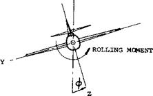
CyP =6 Су U(pb/2V)

Rate of change of lateral-force coefficient with rolling-angular-velocity factor.

СуГ = & Су 16 (rb/2V)

LATERAL STABILITY CHARACTERISTICS OF AIRPLANESRate of change of lateral-force coefficient with yawing-angular-velocity factor.

Systems of Reference. The rolling moment is basically taken about the longitudinal axis of the airplane (air­frame); and the yawing moment is about the axis normal to both the longitudinal axis and the wing span. This system of reference which we may call the airframe system is the one in which a pilot senses position and motion of his airplane. There is also the “wind system”, however; as we may have it, for example, in such wind tunnels where the balance is fixed to the tunnel, while the wing or airplane model is rotated in reference to the balance to produce the angle of yaw. As far as rolling is concerned, the difference between the moment measured about the longitudinal airplane axis and that about the direction of flow or flight is usually very small; it corre­sponds to the cosine of the angle of yaw (1). Accordingly, when considering derivatives taken at small angles of at­tack and about the neutral position (at^ = zero), there is no difference between the two systems as far as moments are concerned. As we will see later, considerable differ­ences can arise, however, in the lateral force Y depending on the direction, either along the wing span or normal to the direction of flow or flight in which it is measured or defined.

Stability Axis. The axis system most universally used is stability axis, figure 1, and is used in this chapter unless otherwise stated. In this system the Z-axis is in the plane of symmetry and perpendicular to the relative wind, the X-axis is in the plane of symmetry of the airplane and is perpendicular to the Z-axis, and the Y-axis is perpendicu­lar to the plane of symmetry. The sign convention used with the stability axis is shown on figure 1. In this sign convention: [124]

LATERAL STABILITY CHARACTERISTICS OF AIRPLANES

Figure 1. Stability axis system, positive direction indicated for forces, moments and displacement.

a) The rolling moment derivative dQ/d^ is considered to be negative when the advancing wing tip (or wing panel) is lifted by the moment.

b) The derivative of the yawing moment is defined as positive when the moment tends to return the airplane to the neutral,^ = 0 position.

c) The lateral force derivative is defined as positive when the force causes the airplane to move to the right.