Category Fundamentals of Aerodynamics

Entropy and the Second Law of Thermodynamics

Consider a block of ice in contact with a red-hot plate of steel. Experience tells us that the ice will warm up (and probably melt) and the steel plate will cool down. However, Equation (7.11) does not necessarily say this will happen. Indeed, the first law allows that the ice may get cooler and the steel plate hotter—just as long as energy is conserved during the process. Obviously, in real life this does not happen; instead, nature imposes another condition on the process, a condition that tells us which direction a process will take. To ascertain the proper direction of a process, let us define a new state variable, the entropy, as follows:

image490[7.13]

where. s’ is the entropy of the system, Sq, cv is an incremental amount of heat added reversibly to the system, and T is the system temperature. Do not be confused by the above definition. It defines a change in entropy in terms of a reversible addition of heat SqKv. However, entropy is a state variable, and it can be used in conjunction with any type of process, reversible or irreversible. The quantity SqKV in Equation

(7.13) is just an artifice; an effective value of SqKy can always be assigned to relate the initial and end points of an irreversible process, where the actual amount of heat

added is 8q. Indeed, an alternative and probably more lucid relation is

Entropy and the Second Law of Thermodynamics

Подпись: 'irrevimage491[7.14]

In Equation (7.14), &q is the actual amount of heat added to the system during an actual irreversible process, and dsmv is the generation of entropy due to the irreversible, dis­sipative phenomena of viscosity, thermal conductivity, and mass diffusion occurring within the system. These dissipative phenomena always increase the entropy:

Подпись: 'irrev[7.15]

In Equation (7.15), the equals sign denotes a reversible process, where by definition no dissipative phenomena occur within the system. Combining Equations (7.14) and

(7.15) , we have

image492[7.16]

Furthermore, if the process is adiabatic, &q = 0, and Equation (7.16) becomes

Подпись: ds > 0[7.17]

Equations (7.16) and (7.17) are forms of the second law of thermodynamics. The second law tells us in what direction a process will take place. A process will proceed in a direction such that the entropy of the system plus that of its surroundings always increases or, at best, stays the same. In our example of the ice in contact with hot steel, consider the system to be both the ice and steel plate combined. The simultaneous heating of the ice and cooling of the plate yield a net increase in entropy for the system. On the other hand, the impossible situation of the ice getting cooler and the plate hotter would yield a net decrease in entropy, a situation forbidden by the second law. In summary, the concept of entropy in combination with the second law allows us to predict the direction that nature takes.

The practical calculation of entropy is carried out as follows. In Equation (7.12), assume that heat is added reversibly; then the definition of entropy, Equation (7.13), substituted in Equation (7.12) yields

Подпись: or Подпись: T ds = de + p dv Подпись: [7.18]

T ds — p dv = de

From the definition of enthalpy, Equation (7.3), we have

Подпись: [7.19]dh = de + p dv + v dp

Combining Equations (7.18) and (7.19), we obtain

Entropy and the Second Law of Thermodynamics

T ds — dh — v dp


[7.20]


Equations (7.18) and (7.20) are important; they are essentially alternate forms of the first law expressed in terms of entropy. For a perfect gas, recall Equations (7.5a and b), namely, de = cvdT and dh = cp dT. Substituting these relations into Equations

(7.18) and (7.20), we obtain

dT pdv

ds = cv— + — [7.21]

dT v dp

and ds=c„—————— [7.22]

p T t

Working with Equation (7.22), substitute the equation of state pv = RT, or v/T = R/p, into the last term:

ds=c„———- R— [7.23]

T P

Consider a thermodynamic process with initial and end states denoted by 1 and 2, respectively. Equation (7.23), integrated between states 1 and 2, becomes

Подпись: 52 - 5)image493[7.24]

Подпись: Pi Подпись: [7.25] Подпись: Ti p2 S2 - Si = cp In — - R In — 11

For a calorically perfect gas, both R and cp are constants; hence, Equation (7.24) becomes

Подпись: T2 V2 S2 — 5] = c„ In R In — Ti vi Подпись: [7.26]

In a similar fashion, Equation (7.21) leads to

Equations (7.25) and (7.26) are practical expressions for the calculation of the entropy change of a calorically perfect gas between two states. Note from these equations that 5 is a function of two thermodynamic variables, for example, 5 = s(p, T), s = 5(u, T).

Line Integrals

Consider a vector field

A = A(x, y, z) = A(r, в, z) = A (г, в, Ф)

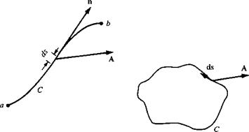
Also, consider a curve C in space connecting two points a and b as shown on the left side of Figure 2.8. Let ds be an elemental length of the curve, and n be a unit vector tangent to the curve. Define the vector ds = n ds. Then, the line integral of A along curve C from point a to point b is

A • ds

If the curve C is closed, as shown at the right of Figure 2.8, then the line integral is given by

J. A • ds

where the counterclockwise direction around C is considered positive. (The positive direction around a closed curve is, by convention, that direction you would move such that the area enclosed by C is always on your left.)

image96

Figure 2.8 Sketch for line integrals.


Condition on Velocity for Incompressible Flow

Consulting our chapter road map in Figure 3.4, we have completed the left branch dealing with Bernoulli’s equation. We now begin a more general consideration of incompressible flow, given by the center branch in Figure 3.4. However, before intro­ducing Laplace’s equation, it is important to establish a basic condition on velocity in an incompressible flow, as follows.

First, consider the physical definition of incompressible flow, namely, p = con­stant. Since p is the mass per unit volume and p is constant, then a fluid element of fixed mass moving through an incompressible flow field must also have a fixed, con­stant volume. Recall Equation (2.32), which shows that V • V is physically the time rate of change of the volume of a moving fluid element per unit volume. However, for an incompressible flow, we have just stated that the volume of a fluid element is constant [e. g., in Equation (2.32), D(SV)/Dt = 0]. Therefore, for an incompressible flow,

Подпись: V • V = 0[3.39]

The fact that the divergence of velocity is zero for an incompressible flow can also be shown directly from the continuity equation, Equation (2.52):

Condition on Velocity for Incompressible Flow

[2.52]


For incompressible flow, p = constant. Hence, dp/dt = 0 and V • (pV) = pV ■ V.

Equation (2.52) then becomes

O + pV • V = 0

or V • V = 0

which is precisely Equation (3.39).

Incompressible Flow. over Finite Wings

The one who has most carefully watched the soaring birds of prey sees man with wings and the faculty of using them.

James Means, Editor of the Aeronautical Annual, 1895

5.1 Introduction: Downwash and Induced Drag

In Chapter 4 we discussed the properties of airfoils, which are the same as the proper­ties of a wing of infinite span; indeed, airfoil data are frequently denoted as “infinite wing” data. However, all real airplanes have wings of finite span, and the purpose of the present chapter is to apply our knowledge of airfoil properties to the analysis of such finite wings. This is the second step in Prandtl’s philosophy of wing theory, as described in Section 4.1. You should review Section 4.1 before proceeding further.

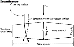
Question: Why are the aerodynamic characteristics of a finite wing any different from the properties of its airfoil sections? Indeed, an airfoil is simply a section of a wing, and at first thought, you might expect the wing to behave exactly the same as the airfoil. However, as studied in Chapter 4, the flow over an airfoil is two-dimensional. In contrast, a finite wing is a three-dimensional body, and consequently the flow over the finite wing is three-dimensional; that is, there is a component of flow in the spanwise direction. To see this more clearly, examine Figure 5.1, which gives the top and front views of a finite wing. The physical mechanism for generating lift on the wing is the existence of a high pressure on the bottom surface and a low pressure

T
Подпись:О

_L

High pressure

Figure 5.1 Finite wing. In this figure, the curvature of the

streamlines over the top and bottom of the wing is exaggerated for clarity.

on the top surface. The net imbalance of the pressure distribution creates the lift, as discussed in Section 1.5. However, as a by-product of this pressure imbalance, the flow near the wing tips tends to curl around the tips, being forced from the high – pressure region just underneath the tips to the low-pressure region on top. This flow around the wing tips is shown in the front view of the wing in Figure 5.1. Asa result, on the top surface of the wing, there is generally a spanwise component of flow from the tip toward the wing root, causing the streamlines over the top surface to bend toward the root, as sketched on the top view shown in Figure 5.1. Similarly, on the bottom surface of the wing, there is generally a spanwise component of flow from the root toward the tip, causing the streamlines over the bottom surface to bend toward the tip. Clearly, the flow over the finite wing is three-dimensional, and therefore you would expect the overall aerodynamic properties of such a wing to differ from those of its airfoil sections.

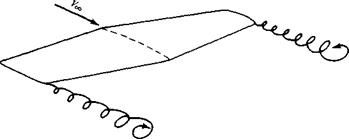
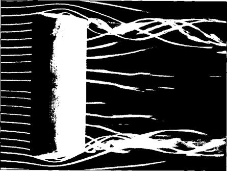
The tendency for the flow to “leak” around the wing tips has another important effect on the aerodynamics of the wing. This flow establishes a circulatory motion that trails downstream of the wing; that is, a trailing vortex is created at each wing tip. These wing-tip vortices are sketched in Figure 5.2 and are illustrated in Figure 5.3. The tip vortices are essentially weak “tornadoes” that trail downstream of the finite wing. (For large airplanes such as a Boeing 747, these tip vortices can be powerful

image402

Figure 5.2 Schematic of wing-tip vortices.

image403

Figure 5.3 Wing-tip vortices from a rectangular wing. The wing is in a smoke tunnel,

where individual streamtubes are made visible by means of smoke filaments.

(Source: Head, M. R., in Flow Visualization II, W. Merzkirch (Ed.), Hemisphere Publishing Co., New York, 1 982, pp. 399-403. Also available in Van Dyke, Milton, An Album of Fluid Motion, The Parabolic Press,

Stanford, CA, 1982.)

enough to cause light airplanes following too closely to go out of control. Such accidents have occurred, and this is one reason for large spacings between aircraft landing or taking off consecutively at airports.) These wing-tip vortices downstream of the wing induce a small downward component of air velocity in the neighborhood

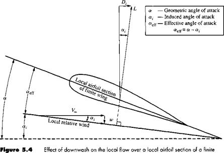
of the wing itself. This can be seen by inspecting Figure 5.3; the two vortices tend to drag the surrounding air around with them, and this secondary movement induces a small velocity component in the downward direction at the wing. This downward component is called downwash, denoted by the symbol w. In turn, the downwash combines with the freestream velocity Voo to produce a local relative wind which is canted downward in the vicinity of each airfoil section of the wing, as sketched in Figure 5.4.

Examine Figure 5.4 closely. The angle between the chord line and the direction of Vqo is Ле angle of attack a, as defined in Section 1.5 and as used throughout our discussion of airfoil theory in Chapter 4. We now more precisely define a as the geometric angle of attack. In Figure 5.4, the local relative wind is inclined below the direction of Vqo by the angle a,, called the induced angle of attack. The presence of downwash, and its effect on inclining the local relative wind in the downward direction, has two important effects on the local airfoil section, as follows:

1. The angle of attack actually seen by the local airfoil section is the angle between the chord line and the local relative wind. This angle is given by «cff in Figure

5.4 and is defined as the effective angle of attack. Hence, although the wing is at a geometric angle of attack a, the local airfoil section is seeing a smaller angle, namely, the effective angle of attack aes. From Figure 5.4,

Qfeff = a — a, [5.1 ]

2. The local lift vector is aligned perpendicular to the local relative wind, and hence is inclined behind the vertical by the angle a,, as shown in Figure 5.4.

image404

wing.

Consequently, there is a component of the local lift vector in the direction of V,*,; that is, there is a drag created by the presence of downwash. This drag is defined as induced drag, denoted by Ц in Figure 5.4.

Hence, we see that the presence of downwash over a finite wing reduces the angle of attack that each section effectively sees, and moreover, it creates a component of drag—the induced drag D,. Keep in mind that we are still dealing with an inviscid, incompressible flow, where there is no skin friction or flow separation. For such a flow, there is a finite drag—the induced drag—on a finite wing. D’Alembert’s paradox does not occur for a finite wing.

The tilting backward of the lift vector shown in Figure 5.4 is one way of visual­izing the physical generation of induced drag. Two alternate ways are as follows:

1. The three-dimensional flow induced by the wing-tip vortices shown in Figures

5.2 and 5.3 simply alters the pressure distribution on the finite wing in such a fashion that a net pressure imbalance exists in the direction of (i. e., drag is created). In this sense, induced drag is a type of “pressure drag.”

2. The wing-tip vortices contain a large amount of translational and rotational ki­netic energy. This energy has to come from somewhere; indeed, it is ultimately provided by the aircraft engine, which is the only source of power associated with the airplane. Since the energy of the vortices serves no useful purpose, this power is essentially lost. In effect, the extra power provided by the engine that goes into the vortices is the extra power required from the engine to overcome the induced drag.

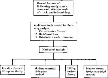
Clearly, from the discussion in this section, the characteristics of a finite wing are not identical to the characteristics of its airfoil sections. Therefore, let us proceed to develop a theory that will enable us to analyze the aerodynamic properties of finite wings. In the process, we follow the road map given in Figure 5.5—keep in touch with this road map as we progress through the present chapter.

In this chapter, we note a difference in nomenclature. For the two-dimensional bodies considered in the previous chapters, the lift, drag, and moments per unit span have been denoted with primes, for example, V, ІУ. and M’, and the correspond­ing lift, drag, and moment coefficients have been denoted by lowercase letters, for example, ci, Cd, and cm. In contrast, the lift, drag, and moments on a complete three­dimensional body such as a finite wing are given without primes, for example, L, D, and M, and the corresponding lift, drag, and moment coefficients are given by capital letters, for example, CL, CD, and CM – This distinction has already been mentioned in Section 1.5.

Finally, we note that the total drag on a subsonic finite wing in real life is the sum of the induced drag /),, the skin friction drag I) /, and the pressure drag Dp due to flow separation. The latter two contributions are due to viscous effects, which are discussed in Chapters 15 to 20. The sum of these two viscous-dominated drag contributions is called profile drag, as discussed in Section 4.3. The profile drag coefficient cj for an NACA 2412 airfoil was given in Figure 4.6. At moderate angle of attack, the profile drag coefficient for a finite wing is essentially the same as for its

image405

Figure 5.5 Road map for Chapter 5.


Подпись: Cd Подпись: Df + Dp Подпись: [5.3]

airfoil sections. Hence, defining the profile drag coefficient as

Подпись: CD, І Подпись: Pi QccS Подпись: [5.3]

and the induced drag coefficient as

the total drag coefficient for the finite wing Co is given by

Подпись: [5.4]Cd = Cd + Co, i

In Equation (5.4), the value of Q is usually obtained from airfoil data, such as given in Figure 4.6. The value of Cd, і can be obtained from finite-wing theory as presented in this chapter. Indeed, one of the central objectives of the present chapter is to obtain an expression for induced drag and to study its variation with certain design characteristics of the finite wing. (See Chapter 5 of Reference 2 for an additional discussion of the characteristics of finite wings.)

Preface to the First Edition

This book is for students—to be read, understood, and enjoyed. It is consciously written in a clear, informal, and direct style designed to talk to the reader and to gain his or her immediate interest in the challenging and yet beautiful discipline of aerodynamics. The explanation of each topic is carefully constructed to make sense to the reader. Moreover, the structure of each chapter is highly organized in order to keep the reader aware of where we are, where we were, and where we are going. Too frequently the student of aerodynamics loses sight of what is trying to be accomplished; to avoid this, we attempt to keep the reader informed of our intent at all times. For example, virtually each chapter contains a road map—a block diagram designed to keep the reader well aware of the proper flow of ideas and concepts. The use of such chapter road maps is one of the unique features of this book. Also, to help organize the reader’s thoughts, there are special summary sections at the end of most chapters.

The material in this book is at the level of college juniors and seniors in aerospace or mechanical engineering. It assumes no prior knowledge of fluid dynamics in general, or aerodynamics in particular. It does assume a familiarity with differential and integral calculus, as well as the usual physics background common to most students of science and engineering. Also, the language of vector analysis is used liberally; a compact review of the necessary elements of vector algebra and vector calculus is given in Chapter 2 in such a fashion that it can either educate or refresh the reader, whichever may be the case for each individual.

This book is designed for a 1-year course in aerodynamics. Chapters 1 to 6 constitute a solid semester emphasizing inviscid, incompressible flow. Chapters 7 to 14 occupy a second semester dealing with inviscid, compressible flow. Finally, Chapters 15 to 18 introduce some basic elements of viscous flow, mainly to serve as a contrast to and comparison with the inviscid flows treated throughout the bulk of the text.

This book contains several unique features:

1. The use of chapter road maps to help organize the material in the mind of the reader, as discussed earlier.

2. An introduction to computational fluid dynamics as an integral part of the begin­ning study of aerodynamics. Computational fluid dynamics (CFD) has recently become a third dimension in aerodynamics, complementing the previously ex­isting dimensions of pure experiment and pure theory. It is absolutely necessary that the modem student of aerodynamics be introduced to some of the basic ideas of CFD—he or she will most certainly come face to face with either its “machinery” or its results after entering the professional ranks of practicing aero – dynamicists. Hence, such subjects as the source and vortex panel techniques, the method of characteristics, and explicit finite-difference solutions are introduced

and discussed as they naturally arise during the course of our discussions. In particular, Chapter 13 is devoted exclusively to numerical techniques, couched at a level suitable to an introductory aerodynamics text.

3. A short chapter is devoted entirely to hypersonic flow. Although hypersonics is at one extreme end of the flight spectrum, it has current important applications to the design of the space shuttle, hypervelocity missiles, and planetary entry vehicles. Therefore, hypersonic flow deserves some attention in any modern presentation of aerodynamics. This is the purpose of Chapter 14.

4. Historical notes are placed at the end of many of the chapters. This follows in the tradition of the author’s previous books, Introduction to Flight: Its Engineering and History (McGraw-Hill, 1978), and Modem Compressible Flow: With His­torical Perspective (McGraw-Hill, 1982). Although aerodynamics is a rapidly evolving subject, its foundations are deeply rooted in the history of science and technology. It is important for the modem student of aerodynamics to have an appreciation for the historical origin of the tools of the trade. Therefore, this book addresses such questions as who were Bernoulli, Euler, d’Alembert, Kutta, Joukowski, and Prandtl; how was the circulation theory of lift developed; and what excitement surrounded the early development of high-speed aerodynamics? The author wishes to thank various members of the staff of the National Air and Space Museum of the Smithsonian Institution for opening their extensive files for some of the historical research behind these history sections. Also, a con­stant biographical reference was the Dictionary of Scientific Biography, edited by С. C. Gillespie, Charles Schribner’s Sons, New York, 1980. This is a 16-volume set of books which is a valuable source of biographic information on the leading scientists in history.

This book has developed from the author’s experience in teaching both incom­pressible and compressible flow to undergraduate students at the University of Mary­land. Such courses require careful attention to the structure and sequence of the presentation of basic material, and to the manner in which sophisticated subjects are described to the uninitiated reader. This book meets the author’s needs at Maryland; it is hoped that it will also meet the needs of others, both in the formal atmosphere of the classroom and in the informal pleasure of self-study.

Readers who are already familiar with the author’s Introduction to Flight will find the present book to be a logical sequel. Many of the aerodynamic concepts first introduced in the most elementary sense in Introduction to Flight are revisited and greatly expanded in the present book. For example, at Maryland, Introduction to Flight is used in a sophomore-level introductory course, followed by the material of the present book in junior – and senior-level courses in incompressible and com­pressible flow. On the other hand, the present book is entirely self-contained; no prior familiarity with aerodynamics on the part of the reader is assumed. All basic principles and concepts are introduced and developed from their beginnings.

The author wishes to thank his students for many stimulating discussions on the subject of aerodynamics—discussions which ultimately resulted in the present book. Special thanks go to two of the author’s graduate students, Tae-Hwan Cho and

Kevin Bowcutt, who provided illustrative results from the source and vortex panel techniques. Of course, all of the author’s efforts would have gone for nought if it had not been for the excellent preparation of the typed manuscript by Ms. Sue Osborn.

Finally, special thanks go to two institutions: (1) the University of Maryland for providing a challenging intellectual atmosphere in which the author has basked for the past 9 years and (2) the Anderson household—Sarah-Alien, Katherine, and Elizabeth—who have been patient and understanding while their husband and father was in his ivory tower.

John D. Anderson, Jr.

Comment

In this section, we have applied the momentum principle (Newton’s second law) to large, fixed control volumes in flows. On one hand, we demonstrated that, by know­ing the detailed flow properties along the control surface, this application led to an accurate result for an overall quantity such as drag on a body, namely, Equation (2.83) for a compressible flow and Equation (2.84) for an incompressible flow. On the other hand, in Example 2.2, we have shown that, by knowing an overall quantity such as the net drag on a flat plate, the finite control volume concept by itself does not necessarily provide an accurate calculation of detailed flow-field properties along the control sur­face (in this case, the velocity profile), although the momentum principle is certainly satisfied in the aggregate. Example 2.2 is designed specifically to demonstrate this fact. The weakness here is the need to assume some form for the variation of flow properties over the control surface; in Example 2.2, the assumption of the particular power-law profile proved to be unsatisfactory.

The Kutta-Joukowski Theorem and the Generation of Lift

Although the result given by Equation (3.140) was derived for a circular cylinder, it applies in general to cylindrical bodies of arbitrary cross section. For example,

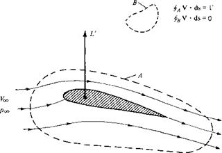
consider the incompressible flow over an airfoil section, as sketched in Figure 3.37. Let curve A be any curve in the flow enclosing the airfoil. If the airfoil is producing lift, the velocity field around the airfoil will be such that the line integral of velocity around A will be finite, that is, the circulation

Подпись:f> Vds

is finite. In turn, the lift per unit span L’ on the airfoil will be given by the Kutta – Joukowski theorem, as embodied in Equation (3.140):

Подпись: L' = P»oVxr[3.140]

This result underscores the importance of the concept of circulation, defined in Section 2.13. The Kutta-Joukowski theorem states that lift per unit span on a two-dimensional body is directly proportional to the circulation around the body. Indeed, the concept of circulation is so important at this stage of our discussion that you should reread Section 2.13 before proceeding further.

The general derivation of Equation (3.140) for bodies of arbitrary cross section can be carried out using the method of complex variables. Such mathematics is beyond the scope of this book. (It can be shown that arbitrary functions of complex variables are general solutions of Laplace’s equation, which in turn governs incompressible potential flow. Hence, more advanced treatments of such flows utilize the mathematics of complex variables as an important tool. See Reference 9 for a particularly lucid treatment of inviscid, incompressible flow at a more advanced level.)

In Section 3.15, the lifting flow over a circular cylinder was synthesized by superimposing a uniform flow, a doublet, and a vortex. Recall that all three elementary flows are irrotational at all points, except for the vortex, which has infinite vorticity at the origin. Therefore, the lifting flow over a cylinder as shown in Figure 3.33 is

image275

Figure 3.37 Circulation around a lifting airfoil.


irrotational at every point except at the origin. If we take the circulation around any curve not enclosing the origin, we obtain from Equation (2.137) the result that Г = 0. It is only when we choose a curve that encloses the origin, where V x V is infinite, that Equation (2.137) yields a finite Г, equal to the strength of the vortex. The same can be said about the flow over the airfoil in Figure 3.37. As we show in Chapter 4, the flow outside the airfoil is irrotational, and the circulation around any closed curve not enclosing the airfoil (such as curve В in Figure 3.37) is consequently zero. On the other hand, we also show in Chapter 4 that the flow over an airfoil is synthesized by distributing vortices either on the surface or inside the airfoil. These vortices have the usual singularities in V x V, and therefore, if we choose a curve that encloses the airfoil (such as curve A in Figure 3.37), Equation (2.137) yields a finite value of Г, equal to the sum of the vortex strengths distributed on or inside the airfoil. The important point here is that, in the Kutta-Joukowski theorem, the value of Г used in Equation (3.140) must be evaluated around a closed curve that encloses the body, the curve can be otherwise arbitrary, but it must have the body inside it. r

At this stage, let us pause and assess our thoughts. The approach we have dis­cussed above—the definition of circulation and the use of Equation (3.140) to obtain the lift—is the essence of the circulation theory of lift in aerodynamics. Its devel­opment at the turn of the twentieth century created a breakthrough in aerodynamics. However, let us keep things in perspective. The circulation theory of lift is an alter­native way of thinking about the generation of lift on an aerodynamic body. Keep in mind that the true physical sources of aerodynamic force on a body are the pres­sure and shear stress distributions exerted on the surface of the body, as explained in Section 1.5. The Kutta-Joukowski theorem is simply an alternative way of ex­pressing the consequences of the surface pressure distribution; it is a mathematical expression that is consistent with the special tools we have developed for the analysis of inviscid, incompressible flow. Indeed, recall that Equation (3.140) was derived in Section 3.15 by integrating the pressure distribution over the surface. Therefore, it is not quite proper to say that circulation “causes” lift. Rather, lift is “caused” by the net imbalance of the surface pressure distribution, and circulation is simply a defined quantity determined from the same pressures. The relation between the surface pres­sure distribution (which produces lift L’) and circulation is given by Equation (3.140), However, in the theory of incompressible, potential flow, it is generally much easier to determine the circulation around the body rather than calculate the detailed surface pressure distribution. Therein lies the power of the circulation theory of lift.

Consequently, the theoretical analysis of lift on two-dimensional bodies in in­compressible, inviscid flow focuses on the calculation of the circulation about the body. Once Г is obtained, then the lift per unit span follows directly from the Kutta- Joukowski theorem. As a result, in subsequent sections we constantly address the question; How can we calculate the circulation for a given body in a given incom­pressible, inviscid flow?

Three-Dimensional. Incompressible Flow

Подпись: Paul Cezanne, 1890

Treat nature in terms of the cylinder, the sphere, the cone, all in perspective.

6.1 Introduction

To this point in our aerodynamic discussions, we have been working mainly in a two-dimensional world; the flows over the bodies treated in Chapter 3 and the airfoils in Chapter 4 involved only two dimensions in a single plane—so-called planar flows. In Chapter 5, the analyses of a finite wing were carried out in the plane of the wing, in spite of the fact that the detailed flow over a finite wing is truly three-dimensional. The relative simplicity of dealing with two dimensions, (i. e., having only two independent variables), is self-evident and is the reason why a large bulk of aerodynamic theory deals with two-dimensional flows. Fortunately, the two-dimensional analyses go a long way toward understanding many practical flows, but they also have distinct limitations.

The real world of aerodynamic applications is three-dimensional. However, because of the addition of one more independent variable, the analyses generally become more complex. The accurate calculation of three-dimensional flow fields has been, and still is, one of the most active areas of aerodynamic research.

The purpose of this book is to present the fundamentals of aerodynamics. There­fore, it is important to recognize the predominance of three-dimensional flows, al­though it is beyond our scope to go into detail. Therefore, the purpose of this chapter is to introduce some very basic considerations of three-dimensional incompressible

flow. This chapter is short; we do not even need a road map to guide us through it. Its function is simply to open the door to the analysis of three-dimensional flow.

The governing fluid flow equations have already been developed in three dimen­sions in Chapters 2 and 3. In particular, if the flow is irrotational, Equation (2.154) states that

V = V0 [2.154]

where, if the flow is also incompressible, the velocity potential is given by Laplace’s equation:

V20 = 0 [3.40]

Solutions of Equation (3.40) for flow over a body must satisfy the flow-tangency boundary condition on the body, that is,

V • n = 0 [3.48a]

where n is a unit vector normal to the body surface. In all of the above equations, ф is, in general, a function of three-dimensional space; for example, in spherical coordinates ф = ф(г, в, Ф). Let us use these equations to treat some elementary three-dimensional incompressible flows.

Inviscid Versus Viscous Flow

A major facet of a gas or liquid is the ability of the molecules to move rather freely, as explained in Section 1.2. When the molecules move, even in a very random fashion, they obviously transport their mass, momentum, and energy from one location to another in the fluid. This transport on a molecular scale gives rise to the phenomena

of mass diffusion, viscosity (friction), and thermal conduction. Such “transport phe­nomena” will be discussed in detail in Chapter 15. For our purposes here, we need only to recognize that all real flows exhibit the effects of these transport phenomena; such flows are called viscous flows. In contrast, a flow that is assumed to involve no friction, thermal conduction, or diffusion is called an inviscidflow. Inviscid flows do not truly exist in nature; however, there are many practical aerodynamic flows (more than you would think) where the influence of transport phenomena is small, and we can model the flow as being inviscid. For this reason, more than 70 percent of this book (Chapters 3 to 14) deals with inviscid flows.

Theoretically, inviscid flow is approached in the limit as the Reynolds number goes to infinity (to be proved in Chapter 15). However, for practical problems, many flows with high but finite Re can be assumed to be inviscid. For such flows, the influence of friction, thermal conduction, and diffusion is limited to a very thin region adjacent to the body surface (the boundary layer, to be defined in Chapter 17), and the remainder of the flow outside this thin region is essentially inviscid. This division of the flow into two regions is illustrated in Figure 1.35. Hence, the material discussed in Chapters 3 to 14 applies to the flow outside the boundary layer. For flows over slender bodies, such as the airfoil sketched in Figure 1.35, inviscid theory adequately predicts the pressure distribution and lift on the body and gives a valid representation of the streamlines and flow field away from the body. However, because friction (shear stress) is a major source of aerodynamic drag, inviscid theories by themselves cannot adequately predict total drag.

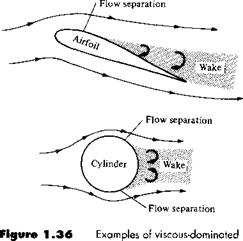
In contrast, there are some flows that are dominated by viscous effects. For example, if the airfoil in Figure 1.35 is inclined to a high incidence angle to the flow (high angle of attack), then the boundary layer will tend to separate from the top surface, and a large wake is formed downstream. The separated flow is sketched at the top of Figure 1.36; it is characteristic of the flow field over a “stalled” airfoil. Separated flow also dominates the aerodynamics of blunt bodies, such as the cylinder at the bottom of Figure 1.36. Here, the flow expands around the front face of the cylinder, but separates from the surface on the rear face, forming a rather fat wake downstream. The types of flow illustrated in Figure 1.36 are dominated by viscous

Flow outside the boundary

layer is inviscid Thin boundary layer of

image63

Figure 1 .35 The division of a flow into two regions: (1) the thin viscous boundary layer adjacent to the body surface and (2) the inviscid flow outside the boundary layer.


image64

flow.


effects; no inviscid theory can independently predict the aerodynamics of such flows. They require the inclusion of viscous effects, to be presented in Part 4.

Relationship Between the Stream Function and Velocity Potential

In Section 2.15, we demonstrated that for an irrotational flow Y = Уф. At this stage, take a moment and review some of the nomenclature introduced in Section 2.2.5 for the gradient of a scalar field. We see that a line of constant ф is an isoline of ф; since ф is the velocity potential, we give this isoline a specific name, equipotential line. In addition, a line drawn in space such that Уф is tangent at every point is defined as a gradient line; however, since Уф = V, this gradient line is a streamline. In turn, from Section 2.14, a streamline is a line of constant Ф (for a two-dimensional flow). Because gradient lines and isolines are perpendicular (see Section 2.2.5, Gradient of a Scalar Field), then equipotential lines (ф = constant) and streamlines (ф = constant) are mutually perpendicular.

To illustrate this result more clearly, consider a two-dimensional, irrotational, incompressible flow in cartesian coordinates. For a streamline, ф(х, у) = constant. Hence, the differential of ф along the streamline is zero; i. e.,

image181[2.159]

From Equation (2.150a and b), Equation (2.159) can be written as

Подпись:йф = —v dx + и dy = 0

2 ф (or тД) can be defined for axisymmetric flows, such as the flow over a cone at zero degrees angle of attack. However, for such flows, only two spatial coordinates are needed to describe the flow field (see Chapter 6).

Relationship Between the Stream Function and Velocity Potential Relationship Between the Stream Function and Velocity Potential

Solve Equation (2.160) for dy/dx, which is the slope of the ф = constant line, i. e., the slope of the streamline:

Подпись: [2.163]dф = и dx + v dy = 0

Relationship Between the Stream Function and Velocity Potential Relationship Between the Stream Function and Velocity Potential

Solving Equation (2.163) for dy /dx, which is the slope of the ф — constant line, i. e., the slope of the equipotential line, we obtain

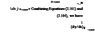
Equation (2.165) shows that the slope of а ф = constant line is the negative reciprocal of the slope of а ф = constant line, i. e., streamlines and equipotential lines are mutually perpendicular.