Category Fundamentals of Aerodynamics

Mach Number Regimes

Of all the ways of subdividing and describing different aerodynamic flows, the dis­tinction based on the Mach number is probably the most prevalent. If M is the local Mach number at an arbitrary point in a flow field, then by definition the flow is locally:

Subsonic if M < I Sonic if M = 1 Supersonic if M > 1

Looking at the whole field simultaneously, four different speed regimes can be iden­tified using Mach number as the criterion:

1. Subsonic flow (M < 1 everywhere). A flow field is defined as subsonic if the Mach number is less than 1 at every point. Subsonic flows are characterized by smooth streamlines (no discontinuity in slope), as sketched in Figure 1.37a. Moreover, since the flow velocity is everywhere less than the speed of sound, disturbances in the flow (say, the sudden deflection of the trailing edge of the airfoil in Figure 1.37a) propagate both upstream and downstream, and are felt throughout the entire flow field. Note that a freestream Mach number M^ less than 1 does not guarantee a totally subsonic flow over the body. In expanding over an aerodynamic shape, the flow velocity increases above the freestream value, and if Moo is close enough to 1, the local Mach number may become supersonic in certain regions of the flow. This gives rise to a rule of thumb that Мж <0.8 for subsonic flow over slender bodies. For blunt bodies, Мж must be even lower to ensure totally subsonic flow. (Again, emphasis is made that the above is just a loose rule of thumb and should not be taken as a precise quantitative definition.) Also, we will show later that incompressible flow is a special limiting case of subsonic flow where M -> 0.

2. Transonic flow (mixed regions where M < landM > 1). As stated above, if

is subsonic but is near unity, the flow can become locally supersonic (M > 1). This is sketched in Figure 1.37b, which shows pockets of supersonic flow over both the top and bottom surfaces of the airfoil, terminated by weak shock waves behind which the flow becomes subsonic again. Moreover, if Mx is increased slightly above unity, a bow shock wave is formed in front of the body; behind this shock wave the flow is locally subsonic, as shown in Figure 1.37c. This subsonic flow subsequently expands to a low supersonic value over the airfoil. Weak shock waves are usually generated at the trailing edge, sometimes in a “fishtail” pattern as shown in Figure 1.37c. The flow fields shown in Figure 1.37b and c are characterized by mixed subsonic-supersonic flows and are dominated by the physics of both types of flow. Hence, such flow fields are called transonic flows. Again, as a rule of thumb for slender bodies, transonic flows occur for freestream Mach numbers in the range 0.8 < Мж < 1.2.

3. Supersonic flow (M > 1 everywhere). A flow field is defined as supersonic if the Mach number is greater than 1 at every point. Supersonic flows are frequently characterized by the presence of shock waves across which the flow properties

(a) Subsonic flow


Mach Number Regimes

Thin, hot shock layer with viscous interaction and chemical reactions


Moo> 5


(e) Hypersonic flow


image65image66image68

Mach Number Regimes

Figure 1.37 Different regimes of flow.

and streamlines change discontinuously (in contrast to the smooth, continuous variations in subsonic flows). This is illustrated in Figure 1.37d for supersonic flow over a sharp-nosed wedge; the flow remains supersonic behind the oblique shock wave from the tip. Also shown are distinct expansion waves, which are common in supersonic flow. (Again, the listing of Мж > 1.2 is strictly a rule of thumb. For example, in Figure 131 d, if 9 is made large enough, the oblique shock

wave will detach from the tip of the wedge, and will form a strong, curved bow shock ahead of the wedge with a substantial region of subsonic flow behind the wave. Hence, the totally supersonic flow sketched in Figure .31d is destroyed if 9 is too large for a given M^. This shock detachment phenomenon can occur at any value of M^ > 1, but the value of в at which it occurs increases as Moo increases. In turn, if 9 is made infinitesimally small, the flow field in Figure l.31d holds for Moo > 1.0. These matters will be considered in detail in Chapter 9. However, the above discussion clearly shows that the listing of Moo > 1-2 in Figure 1.31 d is a very tenuous rule of thumb, and should not be taken literally.) In a supersonic flow, because the local flow velocity is greater than the speed of sound, disturbances created at some point in the flow cannot work their way upstream (in contrast to subsonic flow). This property is one of the most significant physical differences between subsonic and supersonic flows. Is is the basic reason why shock waves occur in supersonic flows, but do not occur in steady subsonic flow. We will come to appreciate this difference more fully in Chapters 7 to 14.

4. Hypersonic flow (very high supersonic speeds). Refer again to the wedge in Fig­ure .31d. Assume 9 is a given, fixed value. As Мж increases above 1, the shock wave moves closer to the body surface. Also, the strength of the shock wave in­creases, leading to higher temperatures in the region between the shock and the body (the shock layer). If Мх is sufficiently large, the shock layer becomes very thin, and interactions between the shock wave and the viscous boundary layer on the surface occur. Also, the shock layer temperature becomes high enough that chemical reactions occur in the air. The O2 and N2 molecules are torn apart; i. e., the gas molecules dissociate. When Мх becomes large enough such that viscous interaction and/or chemically reacting effects begin to dominate the flow (Figure 1.37e), the flow field is called hypersonic. (Again, a somewhat arbitrary but frequently used rule of thumb for hypersonic flow is Мж > 5.) Hypersonic aerodynamics received a great deal of attention during the period 1955-1970 because atmospheric entry vehicles encounter the atmosphere at Mach numbers between 25 (ICBMs) and 36 (the Apollo lunar return vehicle). Again during the period 1985-1995, hypersonic flight received a great deal of attention with the concept of air-breathing supersonic – combustion ramjet-powered transatmo­spheric vehicles to provide single-stage-to-orbit capability. Today, hypersonic aerodynamics is just part of the whole spectrum of realistic flight speeds. Some basic elements of hypersonic flow are treated in Chapter 14.

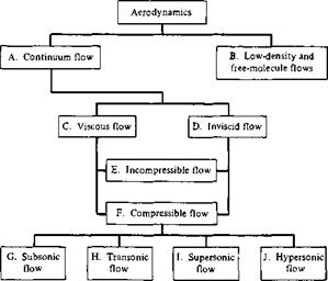
In summary, we attempt to organize our study of aerodynamic flows according to one or more of the various categories discussed in this section. The block diagram in Figure 1.38 is presented to help emphasize these categories and to show how they are related. Indeed, Figure 1.38 serves as a road map for this entire book. All the material to be covered in subsequent chapters fits into these blocks, which are lettered for easy reference. For example, Chapter 2 contains discussions of some fundamental aerodynamic principles and equations which fit into both blocks C and D. Chapters 3 to 6 fit into blocks D and E, Chapter 7 fits into blocks D and F, etc. As we proceed

image69

Figure 1.38 Block diagram categorizing the types of aerodynamic flows.

with our development of aerodynamics, we will frequently refer to Figure 1.38 in order to help put specific, detailed material in proper perspective relative to the whole of aerodynamics.

Theoretical (Analytical) Solutions

Students learning any field of physical science or engineering at the beginning are usually introduced to nice, neat analytical solutions to physical problems that are simplified to the extent that such solutions are possible. For example, when Newton’s second law is applied to the motion of a simple, frictionless pendulum, students in elementary physics classes are shown a closed form analytical solution for the time period of the pendulum’s oscillation, namely,

T = 2njq~g

where T is the period, і is the length of the pendulum, and g is the acceleration of gravity. However, a vital assumption behind this equation is that of small amplitude oscillations. Similarly, in studying the motion of a freely falling body in a gravitational field, the distance у through which the body falls in time t after release is given by

image182

However, this result neglects any aerodynamic drag on the body as it falls through the air. The above examples are given because they are familiar results from elementary physics. They are examples of theoretical, closed-form solutions—straightforward algebraic relations.

The governing equations of aerodynamics, such as the continuity, momentum, and energy equations derived in Sections 2.4, 2.5, and 2.7, respectively, are highly non-linear, partial differential, or integral equations; to date, no general analytical solution to these equations has been obtained. In lieu of this, two different philoso­phies have been followed in obtaining useful solutions to these equations. One of these is the theoretical, or analytical, approach, wherein the physical nature of certain aerodynamic applications allows the governing equations to be simplified to a suffi­cient extent that analytical solutions of the simplified equations can be obtained. One such example is the analysis of the flow across a normal shock wave, as discussed in Chapter 8. This flow is one-dimensional, i. e., the changes in flow properties across the shock take place only in the flow direction. For this case, the у and z derivatives in the governing continuity, momentum, and energy equations from Sections 2.4, 2.5, and 2.7 are identically zero, and the resulting one-dimensional equations, which are still exact for the one-dimensional case being considered, lend themselves to a direct analytical solution, which is indeed an exact solution for the shock wave properties. Another example is the compressible flow over an airfoil considered in Chapters 11 and 12. If the airfoil is thin and at a small angle of attack, and if the freestream Mach number is not near one (not transonic) nor above five (not hypersonic), then many of the terms in the governing equations are small compared to others and can be neglected. The resulting simplified equations are linear and can be solved ana­lytically. This is an example of an approximate solution, where certain simplifying assumptions have been made in order to obtain a solution.

The history of the development of aerodynamic theory is in this category—the simplification of the full governing equations apropos a given application so that analytical solutions can be obtained. Of course this philosophy works for only a limited number of aerodynamic problems. However, classical aerodynamic theory is built on this approach and, as such, is discussed at some length in this book. You can expect to see a lot of closed-form analytical solutions in the subsequent chapters, along with detailed discussions of their limitations due to the approximations necessary to obtain such solutions. In the modem world of aerodynamics, such classical analytical solutions have three advantages:

1. The act of developing these solutions puts you in intimate contact with all the physics involved in the problem.

2. The results, usually in closed-form, give you direct information on what are the important variables, and how the answers vary with increases or decreases in these variables. For example, in Chapter 11 we will obtain a simple equation for the compressibility effects on lift coefficient for an airfoil in high-speed subsonic flow. The equation, Equation (11.52), tells us that the high-speed effect on lift coefficient is governed by just Мж alone, and that as increases, then the lift coefficient increases. Moreover, the equation tells us in what way the lift coefficient increases, namely, inversely with (1 — M^)1/2. This is powerful information, albeit approximate.

3. Finally, the results in closed-form provide simple tools for rapid calculations, making possible the proverbial “back of the envelope calculations” so important in the preliminary design process and in other practical applications.

The Cambered Airfoil

image332

Thin airfoil theory for a cambered airfoil is a generalization of the method for a symmetric airfoil discussed in Section 4.7. To treat the cambered airfoil, return to Equation (4.18):

image333,image334,image335,image336,image337
Recall that Equation (4.46) was obtained directly from Equation (4.42), which is the transformed version of the fundamental equation of thin airfoil theory, Equa­tion (4.18). Furthermore, recall that Equation (4.18) is evaluated at a given point, r along the chord line, as sketched in Figure 4.19. Hence, Equation (4.46) is also eval­uated at the given point x; here, dz/dx and во correspond to the same point л: on the chord line. Also, recall that dz/dx is a function of во, where л: = (c/2)(l — cos0o) from Equation (4.21).

Examine Equation (4.46) closely. It is in the form of a Fourier cosine series ex­pansion for the function of dz/dx. In general, the Fourier cosine series representation of a function f (в) over an interval 0 < в < ж is given by

OO

/((9) = B0 + Bn cos пв [4.47]

n=I

where, from Fourier analysis, the coefficients Bo and Bn are given by

Bo = – f f (в) dO [4.48]

л Jo

2 Г

and Bn — — / f {6)cosn6 d6 [4.49]

л – Jo

(See, e. g., page 217 of Reference 6.) In Equation (4.46), the function dz/dx is analo­gous to f(6) in the general form given in Equation (4.47). Thus, from Equations (4.48) and (4.49), the coefficients in Equation (4.46) are given by

1 Г dz

a – A0 = — —dOо Jr Jo dx

or

1 [л dz

Ao = a—— / — dOo

Jr Jo dx

[4.50]

and

2 Cn dz

An = — / — cos пво dOо n Jo dx

[4.51]

Keep in mind that in the above, dz/dx is a function of в0. Note from Equation (4.50) that Ao depends on both a and the shape of the camber line (through dz/dx), whereas from Equation (4.51) the values of An depend only on the shape of the camber line.

Pause for a moment and think about what we have done. We are considering the flow over a cambered airfoil of given shape dz/dx at a given angle of attack a. In order to make the camber line a streamline of the flow, the strength of the vortex sheet along the chord line must have the distribution у (в) given by Equation (4.43), where the coefficients A0 and An are given by Equations (4.50) and (4.51), respectively. Also, note that Equation (4.43) satisfies the Kutta condition y(n) = 0. Actual numbers for Ao and An can be obtained for a given shape airfoil at a given angle of attack simply by carrying out the integrations indicated in Equations (4.50) and (4.51). For an example of such calculations applied to an NACA 2412 airfoil, see pages 120­125 of Reference 13. Also, note that when dz/dx = 0, Equation (4.43) reduces to Equation (4.24) for a symmetric airfoil. Hence, the symmetric airfoil is a special case of Equation (4.43).

Let us now obtain expressions for the aerodynamic coefficients for a cambered airfoil. The total circulation due to the entire vortex sheet from the leading edge to the trailing edge is

Г= f y(^)d^=C – [ y(0)sm0de JO ^ Jo


The Cambered Airfoil

[4.53]


The Cambered Airfoil

and


The Cambered Airfoil

Hence, Equation (4.53) becomes

Подпись: [4.54]Г — cVqo (ttAq +

From Equation (4.54), the lift per unit span is

L — Poo 1^00 Г — Рсо^оо^ (жА0 3“

In turn, Equation (4.55) leads to the lift coefficient in the form

L’


[4.55]


[4.56]


The Cambered Airfoil

ci


The Cambered Airfoil

Recall that the coefficients A0 and A i in Equation (4.56) are given by Equations (4.50) and (4.51), respectively. Hence, Equation (4.56) becomes

Подпись: dci da [4.57]

and


Lift slope =


[4.58]


— 2tz


Equations (4.57) and (4.58) are important results. Note that, as in the case of the symmetric airfoil, the theoretical lift slope for a cambered airfoil is 2jt. It is a general result from thin airfoil theory that dci/da = 2jt for any shape airfoil. However, the expression for c; itself differs between a symmetric and a cambered airfoil, the difference being the integral term in Equation (4.57). This integral term has physical significance, as follows. Return to Figure 4.4, which illustrates the lift curve for an airfoil. The angle of zero lift is denoted by <xl=q and is a negative value. From the geometry shown in Figure 4.4, clearly

dci, ,

ci = — (a – aL=Q) da

Substituting Equation (4.58) into (4.59), we have

ci = 2n{a — aL=o) [4.60]

Comparing Equations (4.60) and (4.57), we see that the integral term in Equa­tion (4.57) is simply the negative of the zero-lift angle; that is

Подпись: 1 UL= о = n Подпись:image340[4.61]

Hence, from Equation (4.61), thin airfoil theory provides a means to predict the angle of zero lift. Note that Equation (4.61) yields aL=o = 0 for a symmetric airfoil, which is consistent with the results shown in Figure 4.20. Also, note that the more highly cambered the airfoil, the larger will be the absolute magnitude of c/l=o-

Returning to Figure 4.21, the moment about the leading edge can be obtained by substituting у (в) from Equation (4.43) into the transformed version of Equa­tion (4.35). The details are left for Problem 4.9. The result for the moment coefficient is

Аг

~2


The Cambered Airfoil

[4.62]


Substituting Equation (4.56) into (4.62), we have

Г сі n і

Cm, le = — 1^— + ~(Al ~ A2)J


[4.63]


Note that, for dz/dx = 0, A = Аг = 0 and Equation (4.63) reduces to Equa­tion (4.39) for a symmetric airfoil.

The moment coefficient about the quarter chord can be obtained by substituting Equation (4.63) into (4.40), yielding

[4.64]


Cm, с/4 — ^ (Аг A])


Unlike the symmetric airfoil, where ст с/4 = 0, Equation (4.64) demonstrates that cm, c/4 is finite for a cambered airfoil. Therefore, the quarter chord is not the center of pressure for a cambered airfoil. However, note that A1 and Аг depend only on the shape of the camber line and do not involve the angle of attack. Hence, from Equation (4.64), сш, с/4 is independent of a. Thus, the quarter-chord point is the theoretical location of the aerodynamic center for a cambered airfoil.

The location of the center of pressure can be obtained from Equation (1.21):

Cm, leC

Подпись: Clu

[4.66]

Подпись:image341Equation (4.66) demonstrates that the center of pressure for a cambered airfoil varies with the lift coefficient. Hence, as the angle of attack changes, the center of pressure also changes. Indeed, as the lift approaches zero, xcp moves toward infinity; that is, it leaves the airfoil. For this reason, the center of pressure is not always a convenient point at which to draw the force system on an airfoil. Rather, the force-and-moment system on an airfoil is more conveniently considered at the aerodynamic center. (Re­turn to Figure 1.19 and the discussion at the end of Section 1.6 for the referencing of the force-and-moment

image342

Section angle of attack a, degree

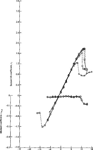
Figure 4.33 Lift – and moment-coefficient data for an NACA 23012 airfoil, for comparison with the theoretical results obtained in Example 4.2.

Note that the results from thin airfoil theory for a cambered airfoil agree very well with the experimental data. Recall that excellent agreement between thin airfoil theory for a symmetric airfoil and experimental data has already been shown in Figure 4.20. Hence, all of the work we have done in this section to develop thin airfoil theory is certainly worth the effort. Moreover, this illustrates that the development of thin airfoil theory in the early 1900s was a crowning achievement in theoretical aerodynamics and validates the mathematical approach of replacing the chord line of the airfoil with a vortex sheet, with the flow tangency condition evaluated along the mean camber line.

This brings to an end our introduction to classical thin airfoil theory. Returning to our road map in Figure 4.2, we have now completed the right-hand branch.

Governing Equations for Inviscid, Compressible Flow

In Chapters 3 to 6, we studied inviscid, incompressible flow; recall that the primary dependent variables for such flows are p and V, and hence we need only two basic equations, namely, the continuity and momentum equations, to solve for these two unknowns. Indeed, the basic equations are combined to obtain Laplace’s equation and

Bernoulli’s equation, which are the primary tools used for the applications discussed in Chapters 3 to 6. Note that both p and T are assumed to be constant throughout such inviscid, incompressible flows. As a result, no additional governing equations are required; in particular, there is no need for the energy equation or energy concepts in general. Basically, incompressible flow obeys purely mechanical laws and does not require thermodynamic considerations.

In contrast, for compressible flow, p is variable and becomes an unknown. Hence, we need an additional governing equation—the energy equation—which in turn in­troduces internal energy e as an unknown. Since e is related to temperature, then T also becomes an important variable. Therefore, the primary dependent variables for the study of compressible flow are p, V, p, e, and T; to solve for these five variables, we need five governing equations. Let us examine this situation further.

To begin with, the flow of a compressible fluid is governed by the basic equations derived in Chapter 2. At this point in our discussion, it is most important for you to be familiar with these equations as well as their derivation. Therefore, before proceeding further, return to Chapter 2 and carefully review the basic ideas and relations contained therein. This is a serious study tip, and if you follow it, the material in our next seven chapters will flow much easier for you. In particular, review the integral and differential forms of the continuity equation (Section 2.4), the momentum equation (Section 2.5), and the energy equation (Section 2.7); indeed, pay particular attention to the energy equation because this is an important aspect which sets compressible flow apart from incompressible flow.

For convenience, some of the more important forms of the governing equations for an inviscid, compressible flow from Chapter 2 are repeated below:

Continuity: From Equation (2.48),

Подпись: vПодпись: simage499[7.39]

From Equation (2.52),

Подпись: [7.40]77 + V • PV = 0

at

Momentum: From Equation (2.64),

Governing Equations for Inviscid, Compressible Flow

From Equations (2.113a to c),


Du dp

image504


[7.42a]


[7.42b]


Dw dp

image506


[7.42c]


image505

Governing Equations for Inviscid, Compressible Flow

Energy: From Equation (2.95),

In regard to the basic equations for compressible flow, please note that Bernoulli’s equation as derived in Section 3.2 and given by Equation (3.13) does not hold for compressible flow; it clearly contains the assumption of constant density, and hence is invalid for compressible flow. This warning is necessary because experience shows that a certain number of students of aerodynamics, apparently attracted by the sim­plicity of Bernoulli’s equation, attempt to use it for all situations, compressible as well as incompressible. Do not do it! Always remember that Bernoulli’s equation in the form of Equation (3.13) holds for incompressible flow only, and we must dismiss it from our thinking when dealing with compressible flow.

As a final note, we use both the integral and differential forms of the above equations in our subsequent discussions. Make certain that you feel comfortable with these equations before proceeding further.

Models of the Fluid: Control Volumes and Fluid Elements

Aerodynamics is a fundamental science, steeped in physical observation. As you proceed through this book, make every effort to gradually develop a “physical feel” for the material. An important virtue of all successful aerodynamicists (indeed, of all successful engineers and scientists) is that they have good “physical intuition,” based on thought and experience, which allows them to make reasonable judgments on difficult problems. Although this chapter is full of equations and (seemingly) esoteric concepts, now is the time for you to start developing this physical feel.

With this section, we begin to build the basic equations of aerodynamics. There is a certain philosophical procedure involved with the development of these equations, as follows:

1. Invoke three fundamental physical principles which are deeply entrenched in our macroscopic observations of nature, namely,

a. Mass is conserved, i. e., mass can be neither created nor destroyed.

b. Newton’s second law: force = mass x acceleration.

c. Energy is conserved; it can only change from one form to another.

2. Determine a suitable model of the fluid. Remember that a fluid is a squishy substance, and therefore it is usually more difficult to describe than a well-defined solid body. Hence, we have to adopt a reasonable model of the fluid to which we can apply the fundamental principles stated in item 1.

3. Apply the fundamental physical principles listed in item 1 to the model of the fluid determined in item 2 in order to obtain mathematical equations which properly describe the physics of the flow. In turn, use these fundamental equations to analyze any particular aerodynamic flow problem of interest.

In this section, we concentrate on item 2; namely, we ask the question: What is a suitable model of the fluid? How do we visualize this squishy substance in order to apply the three fundamental physical principles to it? There is no single answer to this question; rather, three different models have been used successfully throughout the modern evolution of aerodynamics. They are (1) finite control volume, (2) infinitesimal fluid element, and (3) molecular. Let us examine what these models involve and how they are applied.

Wall Boundary Conditions

Подпись: or image226 Подпись: [3.48a] [3.48Ы

If the body in Figure 3.18 has a solid surface, then it is impossible for the flow to penetrate the surface. Instead, if the flow is viscous, the influence of friction between the fluid and the solid surface creates a zero velocity at the surface. Such viscous flows are discussed in Chapters 15 to 20. In contrast, for inviscid flows the velocity at the surface can be finite, but because the flow cannot penetrate the surface, the velocity vector must be tangent to the surface. This “wall tangency” condition is illustrated in Figure 3.18, which shows V tangent to the body surface. If the flow is tangent to the surface, then the component of velocity normal to the surface must be zero. Fet n be a unit vector normal to the surface as shown in Figure 3.18. The wall boundary condition can be written as

Equation (3.48a or b) gives the boundary condition for velocity at the wall; it is expressed in terms of ф. If we are dealing with ф rather than ф, then the wall boundary condition is

Wall Boundary Conditions

[3.48c]


where 5 is the distance measured along the body surface, as shown in Figure 3.18. Note that the body contour is a streamline of the flow, as also shown in Figure 3.18. Recall that ф = constant is the equation of a streamline. Thus, if the shape of the body in Figure 3.18 is given by уъ = fix), then

Подпись: [3.484]^surface — Ф у=}h — Const

is an alternative expression for the boundary condition given in Equation (3.48c).

If we are dealing with neither ф nor ф, but rather with the velocity components и and v themselves, then the wall boundary condition is obtained from the equation of a streamline, Equation (2.118), evaluated at the body surface; that is,

image227[3.48e]

Equation (3.48e) states simply that the body surface is a streamline of the flow. The form given in Equation (3.48e) for the flow tangency condition at the body surface is used for all inviscid flows, incompressible to hypersonic, and does not depend on the formulation of the problem in terms of ф or ф (or ф).

General Lift Distribution

Consider the transformation

у — —— cos в [5.46]

2

where the coordinate in the spanwise direction is now given by в, with 0 < в < л. In terms of в, the elliptic lift distribution given by Equation (5.31) is written as

Г(0) = Г0 sin0 [5.47]

Equation (5.47) hints that a Fourier sine series would be an appropriate expression for the general circulation distribution along an arbitrary finite wing. Hence, assume for the general case that

N

Г(0) = 2bV, A„ sin пв [5.48]

l

where as many terms N in the series can be taken as we desire for accuracy. The coefficients An (where n = 1,…, N) in Equation (5.48) are unknowns; however, they must satisfy the fundamental equation of Prandtl’s lifting-line theory; that is, the An’s must satisfy Equation (5.23). Differentiating Equation (5.48), we obtain

General Lift Distribution

dr

~dy


dr de

d9 dy


General Lift Distribution

[5.49]


Подпись: [5.54]Substituting Equations (5.48) and (5.49) into (5.23), we obtain

2b ■Дл 1 fn y’f «A„ cos «0 , ,

а (во) = —V A„ sin «ft, + аь=о(во) + ————- ^— — dQ [5.50]

7Tc(0o) , 7T Jq cos в — COS Oq

General Lift Distribution General Lift Distribution Подпись: [5.51]

The integral in Equation (5.50) is the standard form given by Equation (4.26). Hence, Equation (5.50) becomes

Examine Equation (5.51) closely. It is evaluated at a given spanwise location; hence, во is specified. In turn, b, с(во), and а/=о(во) are known quantities from the geometry and airfoil section of the finite wing. The only unknowns in Equation (5.51) are the A„’s. Hence, written at a given spanwise location (a specified во), Equation (5.51) is one algebraic equation with N unknowns, Ab A2,…, A„. However, let us choose N different spanwise stations, and let us evaluate Equation (5.51) at each of these N stations. We then obtain a system of N independent algebraic equations with N unknowns, namely, А,, Аг,…, A, y. In this fashion, actual numerical values are obtained for the A„’s—numerical values that ensure that the general circulation distribution given by Equation (5.48) satisfies the fundamental equation of finite-wing theory, Equation (5.23).

2 Ch/2 2h[16]

Cl = 77—- / Г(y)dy = —J2A4 si

J-b/2 J , JO

General Lift Distribution General Lift Distribution Подпись: [5.52]

Now that Г(0) is known via Equation (5.48), the lift coefficient for the finite wing follows immediately from the substitution of Equation (5.48) into (5.26):

Hence, Equation (5.52) becomes

Подпись: [5.53]CL = Аіяу = Ai7tAR

Note that Cl depends only on the leading coefficient of the Fourier series expan­sion. (However, although Cl depends on A i only, we must solve for all the A„’s simultaneously in order to obtain A.)

The induced drag coefficient is obtained from the substitution of Equation (5.48) into Equation (5.30) as follows:

General Lift Distribution

2 b2

~Y


at (в) sin в dd


image428

General Lift Distribution Подпись: [5.55]

The induced angle of attack a, (в) in Equation (5.54) is obtained from the substitution of Equations (5.46) and (5.49) into (5.18), which yields

The integral in Equation (5.55) is the standard form given by Equation (4.26). Hence, Equation (5.55) becomes

E

sin nSo

nA„ ——— [5.56]

, Sin во

In Equation (5.56), 60 is simply a dummy variable which ranges from 0 to ж across the span of the wing; it can therefore be replaced by в, and Equation (5.56) can be written as

E

Подпись:Подпись: sin0sin пв пА„ —

С1Г

1

General Lift Distribution Подпись: [5.58]

Substituting Equation (5.57) into (5.54), we have

General Lift Distribution Подпись: 0 for m ф к ж/2 for m = к Подпись: [5.59]

Examine Equation (5.58) closely; it involves the product of two summations. Also, note that, from the standard integral,

Hence, in Equation (5.58), the mixed product terms involving unequal subscripts (such as A1A2, A2A4) are, from Equation (5.59), equal to zero. Hence, Equation

(5.58) becomes

9,2 / N V

Подпись: = л-AR A Подпись: I + E»(^7 Подпись: [5.60]

cD, i – (J2 nAln) у = лARZ! иЛ»

Substituting Equation (5.53) for Cl into Equation (5.60), we obtain

General Lift Distribution

~%(l+S)

tAR


Cd. i


[5.61]


where S = Y^2 n{An/A] )2. Note that S > 0; hence, the factor 1 + S in Equation

(5.61)

General Lift Distribution Подпись: г2 7reAR Подпись: [5.62]

is either greater than 1 or at least equal to 1. Let us define a span efficiency factor, e, as e = (1 + <5)_1. Then Equation (5.61) can be written as

where e < 1. Comparing Equations (5.61) and (5.62) for the general lift distribution with Equation (5.43) for the elliptical lift distribution, note that 5 = 0 and e = 1 for the elliptical lift distribution. Hence, the lift distribution which yields minimum induced drag is the elliptical lift distribution. This is why we have a practical interest in the elliptical lift distribution.

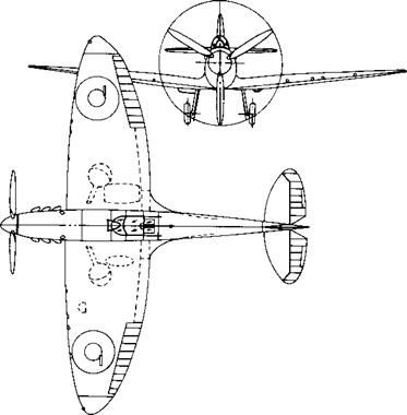
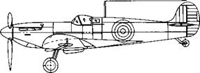
Recall that for a wing with no aerodynamic twist and no geometric twist, an elliptical lift distribution is generated by a wing with an elliptical planform, as sketched at the top of Figure 5.16. Several aircraft have been designed in the past with elliptical wings; the most famous, perhaps, being the British Spitfire from World War II, shown in Figure 5.17. However, elliptic planforms are more expensive to manufacture than, say, a simple rectangular wing as sketched in the middle of Figure 5.16. On the other hand, a rectangular wing generates a lift distribution far from optimum. A compromise is the tapered wing shown at the bottom of Figure 5.16. The tapered wing can be designed with a taper ratio, that is, tip chord/root chord ее ct/cr, such that the lift distribution closely approximates the elliptic case. The variation of S as a function of taper ratio for wings of different aspect ratio is illustrated in Figure 5.18. Such calculations of S were first performed by the famous English aerodynamicist, Hermann Glauert and published in Reference 18 in the year 1926. Note from Figure 5.18 that a tapered wing can be designed with an induced drag coefficient reasonably close to the minimum value. In addition, tapered wings with straight leading and trailing

Elliptic wing

Rectangular wing

image429

Tapered wing

Figure 5*16 Various planforms for straight wings.


image430

image431

Figure 5.1 7 Three views of the Supermarine Spitfire, a famous British World War II fighter.

edges are considerably easier to manufacture than elliptic planforms. Therefore, most conventional aircraft employ tapered rather than elliptical wing planforms.

Aerodynamics: Classification and Practical Objectives

A distinction between solids, liquids, and gases can be made in a simplistic sense as follows. Put a solid object inside a larger, closed container. The solid object will not change; its shape and boundaries will remain the same. Now put a liquid inside the container. The liquid will change its shape to conform to that of the container and will take on the same boundaries as the container up to the maximum depth of the liquid. Now put a gas inside the container. The gas will completely fill the container, taking on the same boundaries as the container.

The word “fluid” is used to denote either a liquid or a gas. A more technical distinction between a solid and a fluid can be made as follows. When a force is applied tangentially to the surface of a solid, the solid will experience a finite deformation, and the tangential force per unit area—the shear stress—will usually be proportional to the amount of deformation. In contrast, when a tangential shear stress is applied to the surface of a fluid, the fluid will experience a continuously increasing deformation, and the shear stress usually will be proportional to the rate of change of the deformation.

The most fundamental distinction between solids, liquids, and gases is at the atomic and molecular level. In a solid, the molecules are packed so closely together that their nuclei and electrons form a rigid geometric structure, “glued” together by powerful intermolecular forces. In a liquid, the spacing between molecules is larger, and although intermolecular forces are still strong they allow enough movement of the molecules to give the liquid its “fluidity.” In a gas, the spacing between molecules is much larger (for air at standard conditions, the spacing between molecules is, on the average, about 10 times the molecular diameter). Hence, the influence of intermolecular forces is much weaker, and the motion of the molecules occurs rather freely throughout the gas. This movement of molecules in both gases and liquids leads to similar physical characteristics, the characteristics of a fluid—quite different from those of a solid. Therefore, it makes sense to classify the study of the dynamics of both liquids and gases under the same general heading, called fluid dynamics. On the other hand, certain differences exist between the flow of liquids and the flow of gases; also, different species of gases (say, N2, He, etc.) have different properties. Therefore, fluid dynamics is subdivided into three areas as follows:

Hydrodynamics—flow of liquids Gas dynamics—flow of gases Aerodynamics—flow of air

These areas are by no means mutually exclusive; there are many similarities and identical phenomena between them. Also, the word “aerodynamics” has taken on a popular usage that sometimes covers the other two areas. As a result, this author tends to interpret the word “aerodynamics” very liberally, and its use throughout this book does not always limit our discussions just to air.

Aerodynamics is an applied science with many practical applications in engineer­ing. No matter how elegant an aerodynamic theory may be, or how mathematically complex a numerical solution may be, or how sophisticated an aerodynamic exper-

iment may be, all such efforts are usually aimed at one or more of the following practical objectives:

1. The prediction of forces and moments on, and heat transfer to, bodies moving through a fluid (usually air). For example, we are concerned with the generation of lift, drag, and moments on airfoils, wings, fuselages, engine nacelles, and most importantly, whole airplane configurations. We want to estimate the wind force on buildings, ships, and other surface vehicles. We are concerned with the hydrodynamic forces on surface ships, submarines, and torpedoes. We need to be able to calculate the aerodynamic heating of flight vehicles ranging from the supersonic transport to a planetary probe entering the atmosphere of Jupiter. These are but a few examples.

2. Determination of flows moving internally through ducts. We wish to calculate and measure the flow properties inside rocket and air-breathing jet engines and to calculate the engine thrust. We need to know the flow conditions in the test section of a wind tunnel. We must know how much fluid can flow through pipes under various conditions. A recent, very interesting application of aerodynamics is high-energy chemical and gas-dynamic lasers (see Reference 1), which are nothing more than specialized wind tunnels that can produce extremely powerful laser beams. Figure 1.5 is a photograph of an early gas-dynamic laser designed in the late 1960s.

image12

Figure 1.5 A CO2-N2 gas-dynamic laser, circa 1969. (Courtesy of the Avco-Everett Research Laboratory.!

The applications in item 1 come under the heading of external aerodynamics since they deal with external flows over a body. In contrast, the applications in item 2 involve internal aerodynamics because they deal with flows internally within ducts. In external aerodynamics, in addition to forces, moments, and aerodynamic heating associated with a body, we are frequently interested in the details of the flow field away from the body. For example, the communication blackout experienced by the space shuttle during a portion of its reentry trajectory is due to a concentration of free electrons in the hot shock layer around the body. We need to calculate the variation of electron density throughout such flow fields. Another example is the propagation of shock waves in a supersonic flow; for instance, does the shock wave from the wing of a supersonic airplane impinge upon and interfere with the tail surfaces? Yet another example is the flow associated with the strong vortices trailing downstream from the wing tips of large subsonic airplanes such as the Boeing 747. What are the properties of these vortices, and how do they affect smaller aircraft which happen to fly through them?

The above is just a sample of the myriad applications of aerodynamics. One purpose of this book is to provide the reader with the technical background necessary to fully understand the nature of such practical aerodynamic applications.

Interim Summary

At this stage, let us pause and think about the various equations we have developed. Do not fall into the trap of seeing these equations as just a jumble of mathematical symbols that, by now, might look all the same to you. Quite the contrary, these equations speak words: e. g., Equations (2.48), (2.52), (2.53), and (2.54) all say that mass is conserved; Equations (2.64), (2.70a to c), (2.71), and (2.72a to c) are statements of Newton’s second law applied to a fluid flow; Equations (2.95) to (2.98) say that energy is conserved. It is very important to be able to see the physical principles behind these equations. When you look at an equation, try to develop the ability to see past a collection of mathematical symbols and, instead, to read the physics that the equation represents.

The equations listed above are fundamental to all of aerodynamics. Take the time to go back over them. Become familiar with the way they are developed, and make yourself comfortable with their final forms. In this way, you will find our subsequent aerodynamic applications that much easier to understand.

Also, note our location on the road map shown in Figure 2.1. We have finished the items on the left branch of the map—we have obtained the basic flow equations containing the fundamental physics of fluid flow. We now start with the branch on the right, which is a collection of useful concepts helpful in the application of the basic flow equations.

Euler—The Origins of Theoretical Fluid Dynamics

Bernoulli’s equation, expressed by Equations (3.14) and (3.15), is historically the most famous equation in fluid dynamics. Moreover, we derived Bernoulli’s equation from the general momentum equation in partial differential equation form. The momentum equation is just one of the three fundamental equations of fluid dynamics—the others being continuity and energy. These equations are derived and discussed in Chapter 2 and applied to an incompressible flow in Chapter 3. Where did these equations first originate? How old are they, and who is responsible for them? Considering the fact that all of fluid dynamics in general, and aerodynamics in particular, is built on these fundamental equations, it is important to pause for a moment and examine their historical roots.

As discussed in Section 1.1, Isaac Newton, in his Principia of 1687, was the first to establish on a rational basis the relationships between force, momentum, and acceleration. Although he tried, he was unable to apply these concepts properly to a moving fluid. The real foundations of theoretical fluid dynamics were not laid until the next century—developed by a triumvirate consisting of Daniel Bernoulli, Leonhard Euler, and Jean Le Rond d’Alembert.

First, consider Bernoulli. Actually, we must consider the whole family of Bernoulli’s because Daniel Bernoulli was a member of a prestigious family that dom­inated European mathematics and physics during the early part of the eighteenth century. Figure 3.51 is a portion of the Bernoulli family tree. It starts with Nikolaus Bernoulli, who was a successful merchant and druggist in Basel, Switzerland, during the seventeenth century. With one eye on this family tree, let us simply list some of the subsequent members of this highly accomplished family:

1. Jakob—Daniel’s uncle. Mathematician and physicist, he was professor of math­ematics at the University of Basel. He made major contributions to the develop­ment of calculus and coined the term “integral.”

2. Johann—Daniel’s father. He was a professor of mathematics at Groningen, Netherlands, and later at the University of Basel. He taught the famous French mathematician L’Hospital the elements of calculus, and after the death of Newton in 1727 he was considered Europe’s leading mathematician at that time.

3. Nikolaus—Daniel’s cousin. He studied mathematics under his uncles and held a master’s degree in mathematics and a doctor of jurisprudence.

4. Nikolaus—Daniel’s brother. He was Johann’s favorite son. He held a master of arts degree, and assisted with much of Johann’s correspondence to Newton and Liebniz concerning the development of calculus.

5. Daniel himself—to be discussed below.

6. Johann—Daniel’s other brother. He succeeded his father in the Chair of Math­ematics at Basel and won the prize of the Paris Academy four times for his work.

7. Johann—Daniel’s nephew. A gifted child, he earned the master of jurisprudence at the age of 14. When he was 20, he was invited by Frederick II to reorganize the astronomical observatory at the Berlin Academy.

8. Jakob—Daniel’s other nephew. He graduated in jurisprudence but worked in mathematics and physics. He was appointed to the Academy in St. Petersburg, Russia, but he had a promising career prematurely ended when he drowned in the river Neva at the age of 30.

With such a family pedigree, Daniel Bernoulli was destined for success.

Daniel Bernoulli was bom in Groningen, Netherlands, on February 8, 1700. His father, Johann, was a professor at Groningen but returned to Basel, Switzerland, in 1705 to occupy the Chair of Mathematics which had been vacated by the death of Jacob Bernoulli. At the University of Basel, Daniel obtained a master’s degree in 1716 in philosophy and logic. He went on to study medicine in Basel, Heidelburg, and Strasbourg, obtaining his Ph. D. in anatomy and botany in 1721. During these studies, he maintained an active interest in mathematics. He followed this interest by moving briefly to Venice, where he published an important work entitled Exerci – tationes Mathematicae in 1724. This earned him much attention and resulted in his winning the prize awarded by the Paris Academy—the first of 10 he was eventually to receive. In 1725, Daniel moved to St. Petersburg, Russia, to join the academy. The St. Petersburg Academy had gained a substantial reputation for scholarship and intellectual accomplishment at that time. During the next 8 years, Bernoulli experi­enced his most creative period. While at St. Petersburg, he wrote his famous book Hydrodynamica, completed in 1734, but not published until 1738. In 1733, Daniel returned to Basel to occupy the Chair of Anatomy and Botany, and in 1750 moved to the Chair of Physics created exclusively for him. He continued to write, give very popular and well-attended lectures in physics, and make contributions to mathematics and physics until his death in Basel on March 17, 1782.

Daniel Bernoulli was famous in his own time. He was a member of virtually all the existing learned societies and academies, such as Bologna, St. Petersburg, Berlin, Paris, London, Bern, Turin, Zurich, and Mannheim. His importance to fluid dynamics is centered on his book Hydrodynamica (1738). (With this book, Daniel introduced the term “hydrodynamics” to the literature.) In this book, he ranged over such topics as jet propulsion, manometers, and flow in pipes. Of most importance, he attempted to obtain a relationship between pressure and velocity. Unfortunately, his derivation was somewhat obscure, and Bernoulli’s equation, ascribed by history to Daniel via his Hydrodynamica, is not to be found in this book, at least not in the form we see it today [such as Equations (3.14) and (3.15)]. The propriety of Equations (3.14) and (3.15) is further complicated by his father, Johann, who also published a book in 1743 entitled Hydraulica. It is clear from this latter book that the father understood Bernoulli’s theorem better than his son; Daniel thought of pressure strictly in terms of the height of a manometer column, whereas Johann had the more fundamental understanding that pressure was a force acting on the fluid. (It is interesting to note the Johann Bernoulli was a person of some sensitivity and irritability, with an overpowering drive for recognition. He tried to undercut the impact of Daniel’s Hydrodynamica by predating the publication date of Hydraulica to 1728, to make it appear to have been the first of the two. There was little love lost between son and father.)

During Daniel Bernoulli’s most productive years, partial differential equations had not yet been introduced into mathematics and physics; hence, he could not ap­proach the derivation of Bernoulli’s equation in the same fashion as we have in Section 3.2. The introduction of partial differential equations to mathematical physics was due to d’Alembert in 1747. d’Alembert’s role in fluid mechanics is detailed in Section 3.20. Suffice it to say here that his contributions were equally if not more important than Bernoulli’s, and d’Alembert represents the second member of the triumvirate which molded the foundations of theoretical fluid dynamics in the eighteenth century.

The third and probably pivotal member of this triumvirate was Leonhard Euler. He was a giant among the eighteenth-century mathematicians and scientists. As a result of his contributions, his name is associated with numerous equations and tech­niques, for example, the Euler numerical solution of ordinary differential equations, eulerian angles in geometry, and the momentum equations for inviscid fluid flow [see Equation (3.12)].

Leonhard Euler was born on April 15, 1707, in Basel, Switzerland. His father was a Protestant minister who enjoyed mathematics as a pastime. Therefore, Euler grew up in a family atmosphere that encouraged intellectual activity. At the age of 13, Euler entered the University of Basel which at that time had about 100 students and 19 professors. One of those professors was Johann Bernoulli, who tutored Euler in mathematics. Three years later, Euler received his master’s degree in philosophy.

It is interesting that three of the people most responsible for the early develop­ment of theoretical fluid dynamics—Johann and Daniel Bernoulli and Euler—lived in the same town of Basel, were associated with the same university, and were con­temporaries. Indeed, Euler and the Bernoulli’s were close and respected friends—so much that, when Daniel Bernoulli moved to teach and study at the St. Petersburg Academy in 1725, he was able to convince the academy to hire Euler as well. At this

invitation, Euler left Basel for Russia; he never returned to Switzerland, although he remained a Swiss citizen throughout his life.

Euler’s interaction with Daniel Bernoulli in the development of fluid mechanics grew strong during these years at St. Petersburg. It was here that Euler conceived of pressure as a point property that can vary from point to point throughout a fluid and obtained a differential equation relating pressure and velocity, that is, Euler’s equation given by Equation (3.12). In turn, Euler integrated the differential equation to obtain, for the first time in history, Bernoulli’s equation in the form of Equations

(3.14) and (3.15). Hence, we see that Bernoulli’s equation is really a misnomer; credit for it is legitimately shared by Euler.

When Daniel Bernoulli returned to Basel in 1733, Euler succeeded him at St. Petersburg as aprofessor of physics. Euler was a dynamic and prolific man; by 1741 he had prepared 90 papers for publication and written the two-volume book Mechanica. The atmosphere surrounding St. Petersburg was conducive to such achievement. Euler wrote in 1749: “I and all others who had the good fortune to be for some time with the Russian Imperial Academy cannot but acknowledge that we owe everything which we are and possess to the favorable conditions which we had there.”

However, in 1740, political unrest in St. Petersburg caused Euler to leave for the Berlin Society of Sciences, at that time just formed by Frederick the Great. Euler lived in Berlin for the next 25 years, where he transformed the society into a major academy. In Berlin, Euler continued his dynamic mode of working, preparing at least 380 papers for publication. Here, as a competitor with d’Alembert (see Section 3.20), Euler formulated the basis for mathematical physics.

In 1766, after a major disagreement with Frederick the Great over some financial aspects of the academy, Euler moved back to St. Petersburg. This second period of his life in Russia became one of physical suffering. In that same year, he became blind in one eye after a short illness. An operation in 1771 resulted in restoration of his sight, but only for a few days. He did not take proper precautions after the operation, and within a few days, he was completely blind. However, with the help of others, he continued his work. His mind was sharp as ever, and his spirit did not diminish. His literary output even increased—about half of his total papers were written after 1765!

On September 18, 1783, Euler conducted business as usual—giving a mathe­matics lesson, making calculations of the motion of balloons, and discussing with friends the planet of Uranus, which had recently been discovered. At about 5 p. m., he suffered a brain hemorrhage. His only words before losing consciousness were “I am dying.” By 11 p. m., one of the greatest minds in history had ceased to exist.

With the lives of Bernoulli, Euler, and d’Alembert (see Section 3.20) as back­ground, let us now trace the geneology of the basic equations of fluid dynamics. For example, consider the continuity equation in the form of Equation (2.52). Although Newton had postulated the obvious fact that the mass of a specified object was con­stant, this principle was not appropriately applied to fluid mechanics until 1749. In this year, d’Alembert gave a paper in Paris, entitled “Essai d’une nouvelle theorie de la resistance des fluides,” in which he formulated differential equations for the conservation of mass in special applications to plane and axisymmetric flows. Euler

took d’Alembert’s results and, 8 years later, generalized them in a series of three basic papers on fluid mechanics. In these papers, Euler published, for the first time in history, the continuity equation in the form of Equation (2.52) and the momentum equations in the form of Equations (2.113a and c), without the viscous terms. Hence, two of the three basic conservation equations used today in modem fluid dynamics were well established long before the American Revolutionary War—such equations were contemporary with the time of George Washington and Thomas Jefferson!

The origin of the energy equation in the form of Equation (2.96) without viscous terms has its roots in the development of thermodynamics in the nineteenth century. Its precise first use is obscure and is buried somewhere in the rapid development of physical science in the nineteenth century.

The purpose of this section has been to give you some feeling for the historical development of the fundamental equations of fluid dynamics. Maybe we can appre­ciate these equations more when we recognize that they have been with us for quite some time and that they are the product of much thought from some of the greatest minds of the eighteenth century.