The thrust required for helicopter hovering is found from the Formula T = G. If we take into account the rotor slipstream flowing over the fuselage, the thrust increases by 1-2% in comparison with the weight. But how can we obtain main rotor thrust equal to the weight of the helicopter? Let us turn /77 to the Formula T = Cj-F(«>/?)’ . The main rotor thrust depends on the thrust coefficient G^, air density p, and rotor angular velocity or rpm.
Knowing the main rotor rpm and the air density in the standard atmosphere, we can calculate the thrust. The thrust coefficient C^, can be found from the formulas
|
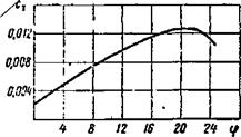
Figure 54. Blade element lift со – r = 0.7; efficient versus angle of attack (Mi-1).
|
|

a7 is the solidity ratio at the radius r = 0.7;
a-j is the angle of attack of the blade element located at the relative radius r = 0.7.
Figure 54 shows the blade profile lift coefficient as a function of angle of attack for various M.
We find Су from the figure and then compute both and main rotor thrust at full rpm at the altitude H = 0 for maximal pitch. With account for blade twist ф7=9° , the induced downwash angle g for the given blade element equals about 4° (see Figure 15b). Then the blade element angle of attack is
«Т = – p = 9 – 4 = 5°.
From the same figure we find C,, —0.42 . Knowing that the solidity a for the Mi-1 main rotor is constant along the radius and equal to 0.05, we find
Г — СУ°- — 0.42-0.05 л “t— 3 2 — ‘ 32 — 0.0066.
 We then find the thrust at maximal engine rpm, knowing that F = 162 m and ш = 26;
This force equals the maximal flight weight for which the Mi-1 can make a vertical takeoff.
We can also determine the coefficient C^, from (19), but with less
Hovering can be performed at different altitudes relative to sea level /78 and at different air temperatures; therefore, we shall examine the dependence of main rotor thrust on the air density.
(21)
This formula shows that the thrust ‘developed by the rotor will diminish with increase of altitude and temperature. In order to accomplish hovering during
takeoff from a high-altitude airfield or at high air temperatures, it is necessary to increase the thrust to the magnitude of the weight force by increasing rotor pitch and rpm. But (20) and (21) indicate that helicopter takeoff weight decreases for takeoff from a high-altitude airfield or with increased air temperature. Therefore, the helicopter has lower takeoff weight in the summer than in the winter.
The power required for helicopter hovering must be supplied to the main
rotor shaft in order to overcome the retarding action of the reactive moment.
It is known that N = M. But at constant rpm req rco *
Therefore, the required main rotor torque and power at constant rpm at constant altitude depend on the torque coefficient m. It was shown in
tor
Chapter 3 that in = ni + m, i. e., this torque coefficient is made tor tor. tor M
x pr
up from the induced drag coefficient and the profile drag coefficient. The induced drag coefficient depends on the induced velocity.
The coefficient m. and the relative induced velocity V. are defined tor J і
by the respective formulas:
where V is the relative induced velocity of the element with r = 0.7
V’^ — 0.52 У Cr.
Knowing the value of for the Mi-1 rotor, we can find the relative induced velocity
Vu = 0.52 у 0.0066 = 0.043.
We substitute this value into (22) and find in
tor
mtor= l. OSC^-f = 1.08-0.0066-0.043+ ^«0.00043.
From (11) and (10) we find the power required for hovering the Mi-1 helicopter at maximal engine rpm.
Knowing the power utilization coefficient (£ = 0.78) , we find the power which must be developed by the engine in hovering
This power is somewhat less than that developed by the AI-26C engine at takeoff power at sea level (575 hp).
The power required to overcome blade induced drag (in creating the induced velocity) can be found from the formula
(23)
Consequently, this power depends on helicopter weight and air density.
The power required to overcome profile drag can be found from the formula
N = pr 100x*
where V is the inverse of the blade element efficiency.
The ratio of the profile drag coefficient to the lift coefficient is termed the reciprocal efficiency of the blade element
 X
X
The blade element reciprocal efficiency varies in the range 0.02-0.04. We see from (24) that the profile power depends on the main rotor rpm. Moreover, if the blade surface roughness is increased, the profile drag coefficient increases and the reciprocal aerodynamic efficiency of the blade element increases. This circumstance must be considered in the wintertime, when the blade may be covered with frost, which leads to a large increase of the profile power.
The profile drag coefficient is highest for blades with fabric covering, lower for blades with plywood covering, and still lower for metal blades. Therefore, main rotors with metal blades are most widely used at the present time. They have recently been installed on the Mi-1 and Mi-4 helicopters and on all the new helicopters.
We can use (23) and (24) to find the induced and profile powers for the Mi-1 helicopter (G = 2200 kgf; = 7.5 m/sec, x=0.9;o)=26;v= 0.03)

 — 136 hp ;
N = N. + N = 245 + 136 = 381 hp. req і pr
|

Figure 55. Hovering at low height.
|
|

This result nearly coincides with that obtained using (10) and (11) — 374 hp.
In the hovering regime the thrust required equals the helicopter weight. If low power is required to achieve this condition, the main rotor has high relative efficiency. On the average the magnitude of this coefficient varies in the range 0.6-0.65 if the main rotor blades operate at the optimal angles of attack (5-6°).
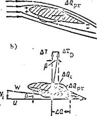
Effect of air cushion on_hovering. The so-called air cushion (Figure 55a) develops during helicopter hovering at low height (H < D). The essence of this phenomenon is as follows. The air from the rotor travels downward and its velocity decreases to zero as it encounters the ground. In this case the pressure below the helicopter increases as a result of the velocity head.
The total pressure at the center of the disk, projected onto on the ground, is
where P is atmospheric pressure.
The thrust force increases as a result of the pressure increase below the /81 rotor. For H = 0.2R the main rotor thrust increases by 50% in comparison with the thrust without the air cushion effect, for H = R the increase is 25%, for H = 2R it is 10%. At the height H = 4R the effect of the air cushion disappears completely.
The variation of the thrust increment under the influence of the air cushion is shown in Figure 55b. The air cushion is used in takeoff with an overload or from a high-altitude airfield, when there is a shortage of power.
The air cushion effect has a favorable influence on helicopter stability, since there will be an increase of the thrust for that portion of the main rotor which is closest to the ground when the rotor tilts to one side, and this leads to the development of a righting moment.


 H
H


