Category Introduction to Structural Dynamics and Aeroelasticity

Wind-Tunnel Models

In this section, we consider three types of mounting for wind-tunnel models: wall – mounted, sting-mounted, and strut-mounted. Expressions for the aeroelastic pitch deflections are developed for these simple models that, in turn, lead to a cursory understanding of the divergence instability. Finally, we briefly return to the wall – mounted model in this section to consider the qualitatively different phenomenon of aileron reversal. All of these wing models are assumed to be rigid and two­dimensional. That is, the airfoil geometry is independent of spanwise location, and the span is sufficiently large that the lift and pitching moment do not depend on a spanwise coordinate.

4.1.1 Wall-Mounted Model

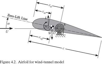
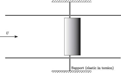
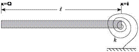
Consider a rigid, spanwise-uniform model of a wing that is mounted to the side walls of a wind tunnel in such a way as to allow the wing to pitch about the support axis, as illustrated in Fig. 4.1. The support is flexible in torsion, which means that it restricts the pitch rotation of the wing in the same way as a rotational spring would. We denote the rotational stiffness of the support by k, as shown in Fig. 4.2. If we assume the body to be pivoted about its support O, located at a distance xO from the leading edge, moment equilibrium requires that the sum of all moments about O must equal zero. Thus

Wind-Tunnel Models

Were the support rigid, the angle of attack would be ar, positive nose-up. The elastic part of the pitch angle is denoted by в, which is also positive nose-up. The wing angle of attack is then a = ar + в. In anticipation of using linear aerodynamics, we assume the angle of attack, a, to be a small angle, such that sin(a) « a and cos(a) « 1. It also is necessary to restrict the analysis to “thin” airfoils (i. e., small thickness to chord and small camber). The treatment herein is restricted to incompressible flow, but compressibility effects may be taken into account by means of Prandtl-Glauert corrections to the airfoil coefficients. For this, the freestream Mach number must remain less than roughly 0.8 to avoid transonic effects.

For linear aerodynamics, the lift for a rigid support is simply

^rigid = qSCLaar (4.2)

whereas the lift for an elastic support is

L = qSCia (ar + в) (4.3)

where q = 1 pmU2 is the freestream dynamic pressure (i. e., in the far field—often denoted by qTO), U is the freestream air speed, pTO is the freestream air density, S is the planform area, and CLa is the wing lift-curve slope. Note that L = L^d; for positive в, L > L-igid. We can express the moment of aerodynamic forces about the aerodynamic center as

Mac = qScCMac (4.4)

If the angle of attack is small, CMac can be regarded as a constant. Note here that linear aerodynamics implies that the lift-curve slope CLa is a constant. A further simplification may be that CLa = 2n in accordance with two-dimensional thin-airfoil theory. If experimental data or results from computational fluid dynamics provide an alternative value, then it should be used.

Using Eqs. (4.3) and (4.4), the equilibrium equation, Eq. (4.1), can be expanded as

qScCMac + qSCia (ar + в) (xo – xac) – W(xq – Xcg) = кв) (4.5)

Solving Eq. (4.5) for the elastic deflection, we obtain

Подпись: (4.6)Подпись: в =qScCMac + qSCLaar (xo – xac) – W(xo – Xcg)

к – qSCLa (xo – Xac)

When ar and q are specified, the total lift can be determined.

When the lift acts upstream of point O, an increase in lift increases a that, in turn, increases lift. Thus, lift is a destabilizing influence counteracting the restraining action of the spring when xO > xac. Recalling the discussion of stability in Section 2.5, when a system is perturbed from a state of equilibrium and tends to diverge further from its equilibrium state, we say that the system is unstable. Such is the case when the moment of the lift about point o exceeds the restoring moment from the spring. This is one of the simplest examples of the static aeroelastic instability called “divergence.” Now, from Eq. (4.6), we see that the aerodynamic center is forward of the support point O when xac < xO, making it possible for the denominator to vanish or for в to blow up when q is sufficiently large. The denominator of the expression for в is a sort of effective stiffness, which decreases as q of increases. When the denominator vanishes, divergence occurs. The divergence dynamic pressure—or dynamic pressure at which divergence occurs—is then denoted by

Подпись: (4.7)к

Подпись: qD =SCia (xo – xac)

Wind-Tunnel Models Подпись: (4.8)

From this, the divergence speed—or the air speed at which divergence occurs—can be found as

It is evident that when the aerodynamic center is coincident with the pivot, so that xo = xac, the divergence dynamic pressure becomes infinite. Also, when the aerodynamic center is aft of the pivot so that xo < xac, the divergence dynamic pressure becomes negative. Because for physical reasons dynamic pressure must be positive and finite, it is clear in either case that divergence is impossible.

To further pursue the character of this instability, consider the case of a symmet­ric airfoil (CMac = 0). Furthermore, let xo = xcg so that the weight term drops out of the equation for в. From Eq. (4.7), we can let к = qDSCLa (xo – xac); therefore, в can be written simply as

в = iDrbi (4.9)

q

The lift is proportional to ar + в. Thus, the change in lift divided by the rigid lift is given by

Подпись:a l = в = g

Lrigid ar 1 – qD

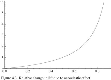
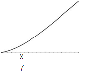
Both в and A L/L-igid clearly approach infinity as q ^ qD. Indeed, a plot of the latter is given in Fig. 4.3 and shows the large change in lift caused by the aeroelastic effect. The lift evidently starts from its “rigid” value—that is, the value it would have were
the support rigid—and increases to infinity as q ^ qD. However, remember that there are limitations on the validity of both expressions. Namely, the lift will not continue to increase as stall is encountered. Moreover, because the structure will not tolerate infinite deformation, failure takes place at some finite value of в—generally at a dynamic pressure well below the divergence dynamic pressure.

When the system parameters are within the bounds of validity for linear theory, another fascinating feature of this problem emerges. We can invert the expression for в to obtain

Подпись: 1 - 1 Ґ1 1 в ar ' q qD

Подпись: LL
Wind-Tunnel Models

(4.11)

making it evident that 1/в is proportional to 1/q (Fig. 4.4). Therefore, for a model of this type, only two data points are needed to extrapolate the line down and to the left until it intercepts the 1/q axis at a distance 1/qD from the origin. As shown in the figure, the slope of this line also can be used to estimate qD. The form of this plot is of great practical value because estimates of qD can be extrapolated from data taken at speeds far below the divergence speed. This means that qD can be estimated even when the values of the model parameters are not precisely known, thereby circumventing the need to risk destruction of the model by testing all the way up to the divergence boundary.

Static Aeroelasticity

I discovered that with increasing load, the angle of incidence at the wing tips increased perceptibly. It suddenly dawned on me that this increasing angle of incidence was the cause of the wing’s collapse, as logically the load resulting from the air pressure in a steep dive would increase faster at the wing tips than at the middle. The resulting torsion caused the wings to collapse under the strain of combat maneuvers.

—A. H. G. Fokker in The Flying Dutchman, Henry Holt and Company, 1931

The field of static aeroelasticity is the study of flight-vehicle phenomena associated with the interaction of aerodynamic loading induced by steady flow and the resulting elastic deformation of the lifting-surface structure. These phenomena are character­ized as being insensitive to the rates and accelerations of the structural deflections. There are two classes of design problems that are encountered in this area. The first and most common to all flight vehicles is the effects of elastic deformation on the air­loads, as well as effects of airloads on the elastic deformation, associated with normal operating conditions. These effects can have a profound influence on performance, handling qualities, flight stability, structural-load distribution, and control effective­ness. The second class of problems involves the potential for static instability of the lifting-surface structure to result in a catastrophic failure. This instability is often termed “divergence” and it can impose a limit on the flight envelope. Simply stated, divergence occurs when a lifting surface deforms under aerodynamic loads in such a way as to increase the applied load, and the increased load deflects the structure further—eventually to the point of failure. Such a failure is not simply the result of a load that is too large for the structure as designed; instead, the aerodynamic forces actually interact with the structure to create a loss of effective stiffness. This phenomenon is explored in more detail in this chapter.

The material presented in this chapter is an introduction to some of these static aeroelastic phenomena. To illustrate clearly the mechanics of these problems and yet maintain a low level of mathematical complexity, relatively simple configurations are considered. The first items treated are rigid aerodynamic models that are elastically mounted in a wind-tunnel test section; such elastic mounting is characteristic of most load-measurement systems. The second aeroelastic configuration to be treated is

Static Aeroelasticity

Figure 4.1. Planform view of a wind-tunnel model on a torsionally elastic support

a uniform elastic lifting surface of finite span. Its static aeroelastic properties are similar to those of most lifting surfaces on conventional flight vehicles.

The Finite Element Method

In this chapter, we considered the free-vibration analysis and modal representa­tion for flexible structures, along with methods for solving initial-value and forced- response problems associated therewith. Moreover, the approximation techniques of the Ritz method, the Galerkin method, and the finite element method were intro­duced. This sets the stage for consideration of aeroelastic problems in Chapters 4 and

5. The static-aeroelasticity problem, addressed in Chapter 4, results from interaction of structural and aerodynamic loads. These loads are a subset of those involved in dynamic aeroelasticity, which includes inertial effects. One aspect of dynamic aeroe – lasticity is flutter, which is discussed in Chapter 5, where it is shown that both the modal representation and the modal approximation methods apply equally well to both types of problems.

The Finite Element Method

Problems

1. By evaluating the appropriate integrals, prove that each function in the following two sets of functions is orthogonal to all other functions in its set over the interval

0 < x <1:

(a) sin (n) for n = 1, 2,3,…

(b) cos (nnx) for n = 0,1, 2,…

Use of a table of integrals may be helpful.

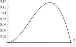
2. Considering Eq. (3.54), plot the displacement at time t = 0 for a varying number of retained modes, showing that as more modes are kept, the shape more closely resembles the initial shape of the string given in Fig. 3.2.

3. Compute the propagation speed of elastic torsional deflections along prismatic, homogeneous, isotropic beams with circular cross sections and made of

(a) aluminum (2014-T6)

(b) steel

Hint: Compare the governing wave equation with that for the uniform-string problem, noting that for beams with a circular cross section, J = Ip.

Answers: (may vary slightly depending on properties used)

(a) 3,140 m/s

(b) 3,110 m/s

4.

Подпись: ¥ <x-0) = V Подпись: 1 cos Подпись: 2n x

For a uniform string attached between two walls with no external loads, deter­mine the total string deflection v(x, t) for an initial string deflection of zero and an initial transverse velocity distribution given by

16VI [m ^ 1 . /nnx

Answer: v(x, t) = T ^ n2(n2 _ 4) sin (~) Sln (“nt), where

The Finite Element Methodnn

= —

I

5. Consider a uniform string of length I and mass per unit length m that has been stretched between two walls with tension T. Transverse vibration of the string is restrained at its midpoint by a linear spring with spring constant k. The spring is unstretched when the string is undeflected. Write the generalized equation of motion for the ith mode, giving particular attention to the writing of the generalized force Ei. As a check, derive the equation taking into account the spring through the potential energy instead of through the generalized force.

Iі + «2| + —(-1) 2 ^ (-1) 2 Ij = 0

Подпись: і = 1, 3,.ж і = 2, 4,.ж

The Finite Element Method
Подпись: Answer: Letting ші are

j=1,3,…

1 + щ21 = 0

6.

Подпись: F = F Подпись: 1 - sin Подпись: 3п x ~r Подпись: cos(Ut)

Consider a uniform string of length £ with mass per unit length m that has been stretched between two walls with tension T. Until the time t = 0, the string is undeflected and at rest. At time t = 0, concentrated loads of magnitude F0 sin Ut are applied at x = £/3 and x = 2£/3 in the positive (up) and negative (down) directions, respectively. In addition, a distributed force

The Finite Element Method Подпись: . ( пп x  sin (~T)

is applied to the string. What is the total string displacement v(x, t) for time t > 0?

+ ^2 [Dn [cos(Ut) – cos («nt)] sin (^ J

п=1,3,… £

The Finite Element Method

where

7. Consider a uniform circular rod of length £, torsional rigidity GJ, and mass moment of inertia per unit length p J. The beam is clamped at the end x = 0, and it has a concentrated inertia IC at its other end where x = £.

(a) Determine the characteristic equation that can be solved for the torsional natural frequencies for the case in which IC = p J£Z, where Z is a dimen­sionless parameter.

(b) Verify that the characteristic equation obtained in part (a) approaches that obtained in the text for the clamped-free uniform rod in torsion as Z approaches zero.

(c) Solve the characteristic equation obtained in part (a) for numerical values of the first four eigenvalues, аі £, і = 1,2, 3, and 4, when Z = 1.

(d) Solve the characteristic equation obtained in part (a) for the numerical value of the first eigenvalue, ail, when Z = 1, 2, 4, and 8. Make a plot of the behavior of the lowest natural frequency versus the value of the concentrated inertia. Note that a1£ versus Z is the same in terms of dimensionless quantities.

Answer:

(a) Zaltan(al) = 1

(c, d) Sample result: a1l = 0.860334 for Z = 1

8. Consider a clamped-free beam undergoing torsion:

(a) Prove that the free-vibration mode shapes are orthogonal, regardless of whether the beam is uniform.

(b)

The Finite Element Method

Given that the kinetic energy is

10. Consider a clamped-free beam undergoing bending:

(a) Prove that the free-vibration mode shapes are orthogonal, regardless of whether the beam is uniform.

(b)

Подпись: 1 * = 2 The Finite Element Method

Given the kinetic energy as

show that К can be written as

where Mi is the generalized mass of the ith mode and ^ is the generalized coordinate for the ith mode.

(c) Given that the potential energy is the internal (i. e., strain) energy; that is

dx

show that P can be written as

Подпись:p = 2J2 Mi «2 ^

where щ is the natural frequency.

(d) Show that for a uniform beam and for фі as given in the text, Mi = ml for all i.

11. Consider a uniform beam with the boundary conditions shown in Fig. 3.38 undergoing bending vibration:

(a) Using the relationships derived in the text, plot the square of characteristic value (a1l)2, which is proportional to the fundamental frequency, versus к from 0 to 100. Check your results versus those given in Fig. 3.40.

(b) Plot the fundamental mode shape for values of к of 0.01,0.1,1,10, and 100. Suggestion: use Eq. (3.270). Check your results for к = 1 with those given in Fig. 3.39; your results for к = 100 will not differ significantly from those in Fig. 3.41, in which к = 50.

12. Find the free-vibration frequencies and plot the mode shapes for the first five modes of a beam of length l, having bending stiffness EI and mass per unit length m, that is free at its right end, and that has the sliding condition (see Fig. 3.26) at its left end. Normalize the mode shapes to have unit de­flection at the free end and determine the generalized mass for the first five

modes. ________ _____________________

Answer: щ = 0, щ = 5.59332^EI/(ml4), щ = 30.2258^EI/(ml4), щ =

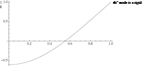
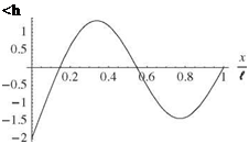
74.6389^EI/(ml4), «4 = 138.791^EI/(ml4); M0 = ml and Mt = ml/4 for i = 1, 2,…, to. As a sample of the mode shapes, the first elastic mode is plotted in Fig. 3.48.

13. Consider the beam in Problem 12. Add to it a translational spring restraint at the left end, having spring constant к = к EI/l2. Find the first three free-vibration frequencies and mode shapes for the cases in which к takes on values of 0.01,1, and 100. Plot the mode shapes, normalizing them to have unit deflection at the free end.

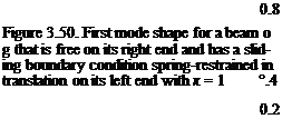
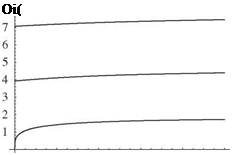
Answer: Sample results: A plot versus к of (a, l)2 for i = 1, 2, and 3 is shown in Fig. 3.49, and the first mode shape for к = 1 is shown in Fig. 3.50.

14. Consider a beam that at its left end is clamped and at its right end is pinned with a rigid body attached to it. Let the mass moment of inertia of the rigid body be given by Ic = ц-ml2 where C coincides with the pin (i. e., a pirot).

(a) Find the first two free-vibration frequencies for values of л equal to 0.01, 0.1, 1, 10, and 100. Comment on the variation of the natural frequencies versus л.
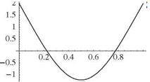
Подпись: Ш2

The Finite Element Method

Figure 3.49. Variation versus к of (a, l)2 for i = 1, 2, and 3, for a beam that is free on its right end and has a sliding bound­ary condition spring-restrained in trans­lation on its left end

x

0.2 0.4 0.6 0.8 1 7

(b) Choose any normalization that is convenient and plot the first mode shape for these same values of д. Comment on the variation of the mode shapes versus д.

Answer:

(a) Sample result: = 1.99048^^17 for д = 1.

(b) Sample result: The first mode shape for д = 1 is shown in Fig. 3.51.

15. Consider a uniform clamped-free beam of length l, bending rigidity El, and mass per unit length m. Until time t = 0, the beam is undeflected and at rest. At time t = 0, a transverse concentrated load of magnitude F cos(Q. t) is applied at

x = l.

(a) Write the generalized equations of motion.

(b) Determine the total beam displacement v(x, t) for time t > 0.

(c) For the case when ^ = 0, determine the tip displacement of the beam. Ignoring those terms that are time dependent (they would die out in a real beam because of dissipation), plot the tip displacement versus the number of mode shapes retained in the solution up to five modes. Show the static tip deflection from elementary beam theory on the plot. (This part of the problem illustrates how the modal representation can be applied to static – response problems.)

Подпись: 1Подпись:Подпись: 0.4Подпись: 0.6Подпись:The Finite Element Method

The Finite Element Method
Подпись: 0.8 Figure 3.50. First mode shape for a beam о g that is free on its right end and has a sliding boundary condition spring-restrained in translation on its left end with к = 1 °.4 0.2

Figure 3.51. First mode shape for a beam that is clamped on its left end and pinned with a rigid body attached on its right end with д = 1

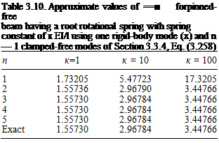
Подпись: Table 3.10. Approximate values of ==■ forpinned-free beam having a root rotational spring with spring constant of к EI/l using one rigid-body mode (x) and n — 1 clamped-free modes of Section 3.3.4, Eq. (3.258) n к=1 к = 10 к = 100 1 1.73205 5.47723 17.3205 2 1.55736 2.96790 3.44766 3 1.55730 2.96784 3.44766 4 1.55730 2.96784 3.44766 5 1.55730 2.96784 3.44766 Exact 1.55730 2.96784 3.44766

Answer:

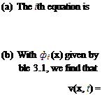
Подпись: (a) The ith equation is (b) With фі (x) given by ble 3.1, we find that v(x, t) = fi + afe = 2(—1)+lF cos(Qt) ml

Eq. (3.258), a = (al)2JmL, and ail as given in Ta – 2 F ^ (—1)+1

mill шг_ Q2 [cos(Qt) — cosM)]Фі(x)

i=1 i

(c) The result converges within engineering accuracy to FE= using only a few terms.

16. Consider a free-free beam with bending stiffness EI, mass per unit length m, and length l. Applying the Ritz method, write the equations of motion for a system that consists of the beam plus identical rigid bodies attached to the ends, where each body has a moment of inertia IC and mass mc. Use as assumed modes those of the exact solution of the free-free beam without the attached bodies, obtained in the text. Note the terms that provide inertial coupling.

17. Consider a pinned-free beam with the rotation about the hinge restrained by a light spring of modulus к EI/l. Use a rigid-body rotation plus the set of clamped-free modes as the assumed modes of the Ritz method. Compare the

l4

Table 3.11. Approximate values of a2J = for pinned-free beam having a root rotational spring with spring constant of к EI/l using one rigid-body mode (x) and n — 1 clamped-free modes of Section 3.3.4, Eq. (3.258)

n

к=1

к = 10

к = 100

2

22.8402

37.9002

103.173

3

16.2664

19.3632

21.6202

4

16.2512

19.3563

21.6200

5

16.2502

19.3559

21.6200

Exact

16.2501

19.3558

21.6200

cor pinned-free beam

Table 3.12. Approximate values

having a root rotational spring with spring constant of к EI /l using one rigid-body mode (x) and n — 1 polynomials that satisfy clamped-free beam boundary conditions

n

к=1

к = 10

к = 100

1

1.73205

5.47723

17.3205

2

1.55802

2.97497

3.46064

3

1.55730

2.96784

3.44768

4

1.55730

2.96784

3.44766

Exact

1.55730

2.96784

3.44766

results for the first two modes using a varying number of terms for к = 1,10, and 100.

Answer: See Tables 3.10 and 3.11.

18. Repeat Problem 17 using a set of polynomial admissible functions. Use one rigid-body mode (x) and a varying number of polynomials that satisfy all the boundary conditions of a clamped-free beam.

Answer: See Tables 3.12 and 3.13.

19. Consider a clamped-free beam of length l for which the mass per unit length and bending stiffness vary according to

m = m0[1 — i + xj)

E = EI0 (‘ — l + к j)

Using the comparison functions in Eq. (3.325), apply the Ritz method to de­termine approximate values for the first three natural frequencies, varying the number of terms from one to five. Let x = к = 1/2.

Answer: See Table 3.14.

20. Rework Problem 19 using the Ritz method and the set of polynomial admissible functions (x/l)1+1, i = 1, 2,…, n

Answer: See Table 3.15.

Table 3.13. Approximate values of &>2y E4 for pinned-free beam

having a root rotational spring with spring constant of к EI/l using one rigid-body mode (x) and n — 1 polynomials that satisfy clamped-free beam boundary conditions

n

к=1

к = 10

к = 100

2

24.8200

41.1049

111.743

3

16.4047

19.7070

22.2338

4

16.2508

19.3565

21.6208

Exact

16.2501

19.3558

21.6200

Table 3.14. Approximate values of for a tapered,

clamped-free beam based on the Ritz method with n polynomials that satisfy all the boundary conditions of a clamped-free beam

n

Ю2М

1

4.36731

_

_

2

4.31571

24.7653

3

4.31517

23.5267

69.8711

4

4.31517

23.5199

63.2441

5

4.31517

23.5193

63.2415

Exact

4.31517

23.5193

63.1992

21. Rework Problem 19 using Eq. (3.329) with f = 0 as the equation of motion and the set of polynomial comparison functions (x/£)‘+1, i = 1, 2,…, n.

Answer: See Table 3.16.

22. Consider a clamped-free beam to which is attached at spanwise location x = lr a particle of mass pml. Using a two-term Ritz approximation based on the functions in Eq. (3.325), plot the approximate value for the fundamental natural frequency as a function of r for p = 1.

ans.: See Fig. 3.52.

23. Consider a clamped-free beam undergoing coupled bending and torsion. Set up an approximate solution based on the Ritz method for the dimensionless frequency parameter

2 mlArn2

k2 = __

El

using the uncoupled bending and torsional mode shapes as assumed modes, and with the parameters pIp = 0.01m*2, md2 = 0.25pIp, K2 = 0.25GJ El, and GJ/EI = 5. Answer these questions: How do the signs of d and K affect the frequencies? How do they affect the predicted mode shapes?

Table 3.15. Approximate values of for a tapered,

clamped-free beam based on the Ritz method with n terms of the form (x/lf +1, i = 1, 2, …, n

n

Ю2^Щ

1

5.07093

2

4.31883

33.8182

3

4.31732

23.6645

110.529

4

4.31523

23.6640

64.8395

5

4.31517

23.5226

64.7821

Exact

4.31517

23.5193

63.1992

n

-2УЇІ

1

7.88811

_

_

2

4.45385

54.5221

3

4.19410

24.3254

175.623

4

4.33744

21.4784

67.1265

5

4.31379

23.8535

53.6214

Exact

4.31517

23.5193

63.1992

Table 3.16. Approximate values of щ E – for a tapered, clamped-free beam based on the Galerkin method applied to Eq. (3.329) with n terms of the form (x/l )1 +1, i = 1, 2, …, n

24. Repeat Problem 23 using an appropriate power series for bending and for torsion.

25. Develop a finite-element solution for the static twist of a clamped-free beam in torsion, accounting for linearly varying GJ (x) within each element. Compare results for the tip rotation caused by twisting, with identical loading and proper­ties (i. e., GJ (0) = GJ о = 2GJ (l), r (x, t) = r = const.). Note that the results in Section 3.5.3 approximate the linearly varying GJ as piecewise constant within elements, whereas here you are to assume piecewise linearly varying GJ within elements.

Answer: The results do not change; see Table 3.9.

26.

Подпись: Ш j
Подпись: 3.5 -
The Finite Element Method

Set up a finite-element solution for the dimensionless natural frequencies of a beam in bending m(0)l4«2/[EI(0)] from Section 3.5.3, accounting for linearly

Figure 3.52. Approximate fundamental frequency for a clamped-free beam with a particle of mass ml attached at x = rl

Table 3.17. Finite-element results for the natural frequencies of a beam in bending with linearly varying EI(x), such that EI(0) = EI0 = 2EI(l) and values of EI are taken as linear within each element

n

1

4.31883

33.8182

_

2

4.31654

23.6457

75.9255

3

4.31549

23.5835

63.8756

4

4.31528

23.5430

63.6528

5

4.31522

23.5296

63.4128

6

4.31519

23.5244

63.3088

Exact

4.31517

23.5193

63.1992

varying EI(x) and m(x) within each element. Compare [ M] and [ K] matrices obtained for the case developed in the text (i. e., piecewise constant EI and m within elements) with those obtained for linearly varying within elements. Tabulate dimensionless frequencies for the first three modes, assuming elements of constant length, EI(l) = 0.5EI(0), and m(l) = 0.5m(0).

Answer: See Table 3.17.

The Finite Element Method

The finite element method is, by far, the most popular way of solving realistic structural dynamics and aeroelasticity problems in industry. The name derives from the breaking of a structure into a large number of small elements, modeling them approximately, and connecting them together appropriately. Because of this way of discretizing the geometry, it is possible to accurately capture modeling details that other methods cannot.

In one sense, the finite element method can be regarded as a special case of Ritz and Galerkin methods, one in which the generalized coordinates are themselves dis­placements and/or rotations at points along the structure. It typically makes use of polynomial shape functions over each of the finite elements into which the original structure is broken. Equations based on the finite element method have the same structure as Eq. (3.304); however, they are typically of large order, with n being on the order of 102 to 107. What keeps the computational effort from being overly burdensome is that the matrices have a narrow-banded structure, which allows spe­cialized software to be used in solving the equations of motion that takes advantage of this structure, reducing both memory and floating-point operations and resulting in significant computational advantages.

Here, we present only a simple outline of the method as applied to beams in torsion and in bending, leaving more advanced topics such as plates and shells to textbooks devoted to the finite element method, such as those by Reddy (1993) and Zienkiewicz and Taylor (2005).

Application to Beams in Torsion. Here, we use the finite element method to analyze the behavior of a nonuniform beam in torsion. Similar to the application of the Ritz method, we make use of Lagrange’s equation. Regardless of how finite elements are derived, however, for a sufficiently fine mesh, the results should approach the exact structural behavior. This development encompasses both forced response and free vibration.

Consider a clamped-free beam subjected to a distributed torque r (x, t) as de­picted in Fig. 3.44. Note that the x coordinate is along the beam. The strain energy

where GI (x) is the torsional stiffness of the wing and в (x, t) is the elastic twist. In the finite-element approach, the beam is divided into n elements, as shown in Fig. 3.45. Although there is no requirement to make the elements of constant stiffness, we do so for convenience. Relaxation of this assumption is left as an exercise for readers (see Problem 25). Element i is connected to two end nodes i and i + 1 with coordinates Xi and xi+1, respectively. Within element i, the torsional stiffness is assumed to be a constant, GI і. The discrete value of the twist at the node i is denoted et. The twist is linearly interpolated between the nodal values so that

e(xt)=I1 – f Ы (3334)

where

z = X(3.335) with 0 < z < 1. The expression for в (x, t) also can be written as

в(x, t) = ві (t) + [ві+1(t) – ві (t)] (3.336)

ti

where xi < x < xi+1 and ti = xi+1 – xi. Note that if all ві are zero except one, then only the element immediately to the left (element i – 1) and immediately to the right (element i) are affected (Fig. 3.46). Introducing this approximation into the strain energy, Eq. (3.333), and integrating over the beam length yields

1

The Finite Element Method

The Finite Element Method

Figure 3.46. Assumed twist distribution for all nodal values equal to zero except 0,


where the array {0} stores the values of the twist at the nodes

{0(t)}Г = |_0i(t) 02(t) • • • @n+i(t)J (3.338)

The resulting stiffness matrix [К] may be written as

Note that we could add the potential energy of springs attached to ground at any nodes to represent elastic restraints.

The kinetic energy may be written as

The Finite Element Method(3.340)

Using the same interpolation for 0 (x, t) and a constant mass polar moment of inertia per unit length in p Ipi in element i, we obtain a discretized kinetic energy of the form

Подпись: (3.34i)1 T

К = 2 {0}T[M] {0}

(3.342)

We also could add concentrated inertia at any nodes to represent the inertia of any attached rigid bodies.

The contribution of the applied torque r (x, t) comes into the analysis through the generalized force, which may be extracted from the virtual work, given by Eq. (2.46) and repeated here for convenience as

8 W = f r (x, t)89(x, t)dx (3.343)

J0

Here, it is helpful to represent the twisting moment using the same shape functions as for в, viz.

Подпись: (3.344)r(x, t) = ri(t) + (x – x) [fi+i(t) – ri(t)]

with the array

{r}T = Lr1 r2 •••r„+1j (3.345)

representing the nodal values of the applied torque per unit span. The virtual work then becomes

Подпись: (3.346)8W ={8в}T[D] {r(t)}

so that the generalized force then may be put into the form

with the loading matrix [ D given by

As for the boundary conditions, admissibility requires only that we satisfy the geometric boundary conditions (see Section 3.5.1). If we consider, for example, a clamped-free beam, we need only set в1 = 0. The boundary condition at the free end (i. e., zero twisting moment) is a “natural” (i. e., a force or moment) boundary condition, not a geometric condition. Therefore, it need not be taken into account in a solution by this approach. As a consequence, the first elements of column matrices [в} and [r} are removed; the reason the first element of the latter is removed is that 8в1 = 0, in keeping with the requirement that the virtual displacements and rotations must satisfy the geometric boundary conditions. This has the effect of removing the first row and column from each of the matrices [M] and [ K, and the first row from [ D].

Подпись: d / dK dU dt Щв}) + В~[в} Подпись: {2} Подпись: (3.349)

The equations of motion now may be formed by use of Lagrange’s equation, as with the Ritz method. Given the approximation of the twist field in Eq. (3.336), the only unknowns of the problem are the nodal twist angles et. Thus, the equations of motion may be written as:

or

[M {в} + [K [в} = [D {r(t)} (3.350)

Although the size of the system matrices in the finite element method can be very large, these matrices possess important properties. First, as noted previously in the discussion of the Ritz method (see Section 3.5.1), they are symmetric, which here is a reflection of their having been derived from energy methods applied to conservative systems. Second, they are banded; that is, the nonvanishing entries are concentrated around the diagonals of the matrices. Third, [M is positive definite and [K is at least positive semidefinite. In the absence of rigid-body modes, [K is positive definite because it results from the computation of the strain energy of the structure, itself a positive-definite quantity when rigid-body motion is excluded.

With these equations, we may look at several types of problems for the nonuni­form beam in torsion. For example:

1. The static response of the beam may be found if [r} is not a function of time. For this, we do not need the mass matrix [M]. Thus

[K] [9} = [D] {r} (3.351)

2. The free-vibration characteristics of the beam may be found by setting r = 0, assuming simple harmonic motion such that [9} = [9} exp(imt) and solving the eigenvalue problem

[K] {9} = m2[M] {9} (3.352)

3. If [r (t)} has the form [Г} exp(iШ) with [r} and ^ specified constants, the steady-state response to harmonic excitation maybe found by assuming [9 }(t) = [99} exp(i Ш) and solving the algebraic equations

[[K] – ^2[M]] {99} = [D] [r} (3.353)

4. Finally, the forced response of the structure may be determined by numerical integration of Eqs. (3.350) subject to appropriate initial conditions—that is, specified values for 9i (0) and 9і (0).

Complex structures including entire aircraft can be modeled with the finite element method. The resulting discretized equations are similar to Eq. (3.350), where [9} is an array of nodal displacements and/or rotations, {r(t)} an array of nodal forces and/or torques, [K] is a stiffness matrix characterizing the elastic be­havior of the entire structure, and [M] is a mass matrix characterizing the iner­tia properties of the entire structure. As the complexity of the model increases, the various arrays increase in size. For the most general types of models, such as those based on three-dimensional brick elements, hundreds of thousands of de­grees of freedom or more may be required to accurately model a complete wing structure.

As an illustrative example, results obtained for the tip rotation caused by twisting of a beam with linearly varying GJ(x) with GJ(0) = GJ0 = 2GJ(£), r (x, t) = r = const., and constant values of GJ within each element are presented in Table 3.9. The convergence is monotonic, and the answers are evidently upper bounds.

Application to Beams in Bending. As another example of applying the finite ele­ment method, we next turn to its application to beams in bending. The theory of bending for beams was presented in terms of strain energy, kinetic energy, and vir­tual work; this framework is sufficient for constructing a finite-element model for nonuniform beams in bending. Again, strictly for simplicity, we assume the bending stiffness and mass per unit length to be constants, respectively equal to EIi and mi within element i. Allowing for linearly varying EI and m within each element is

n

r t2

Щ

1

0.666667

2

0.628571

3

0.620491

4

0.617560

5

0.616184

6

0.615431

7

0.614976

exact

0.613706

Table 3.9. Finite-element results for the tip rotation caused by twist of a beam with linearly varying GJ (x) such that GJ (0) = GJ0 = 2GJ (t), r (x, t) = r = const., and constant values of GJ within each element

left as an exercise for readers (see Problem 26). We consider a beam loaded with a distributed force per unit length f (x, t) and a distributed bending moment per unit length q(x, t) as shown in Fig. 3.47.

Подпись: -=2 Подпись: (3.354)
The Finite Element Method

As with the beam in torsion, we now develop the stiffness matrix from the strain energy. The strain energy is given by

where v(x, t) is represented in terms of nodal displacements vi (t) and rotations в (t). The latter is in the sense of the bending slope в(x, t) = dv(x, t)/дx. When x is between nodes i and i +1, v(x, t) is approximated as
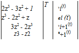
Подпись: 2z3 - 3z2 + 1 T vi(t) z3 - 2z2 + z ві (t) 3z2 - 2z3 vi+1(t) z3 - z2 в+1(t) Подпись:(3.355)

The Finite Element Method

Подпись: xc.

Figure 3.47. Schematic of a nonuniform beam with distributed force and bending moment per unit length

where

z = ^ (3.356)

with 0 < z < 1. The four cubic polynomials in Eq. (3.355) are called “Hermite poly­nomials.” They have the property that one of their values or derivatives at the ends (i. e., where z = 0 or z = 1) is equal to unity whereas the other three are equal to zero. This way, the element degrees of freedom are displacements or rotations at the ends of the

for the two-element case. Note that the contributions from element 1 are all in the upper-left 4×4 submatrix, whereas the contributions from element 2 are all in the lower-right 4×4 submatrix. The two overlap at the 2×2 submatrix in the middle for degrees of freedom associated with the node at the right end of element 1 and at the left end of element 2. With this pattern in mind, it is a straightforward matter to expand the matrix to an arbitrary number of elements.

Подпись: 1
The Finite Element Method

The kinetic energy is given by

that with the specified interpolation can be written in discretized form as

1 T

K = 2 {1}T [M] {1} (3.361)

with the mass matrix given by

(3.362)

again for the two-element case. This pattern is the same as that of the stiffness matrix, so it is also a straightforward matter to expand the mass matrix to an arbitrary number of elements.

Finally, the contributions of the applied distributed force and bending moment are determined using the virtual work. If we interpolate both f (x, t) and q(x, t) in the same way that r (x, t) was treated for torsion, viz.

f (x, t) = f (t) + [ f+1(t) – f (t)]

‘ (3.363)

(x x )

q(x, t) = q (t) + [qi+i(t) – q (t)]

with the arrays f(t) and q(t) representing the nodal values of the applied force and bending moment per unit span

Подпись:{f }T = Lfi f2 •" fn+ii {q}T = Lqi q2 •••qn+ii

the virtual work then becomes

Подпись: (3.365)~SW = {SWT [Df] {f (t)} + {Sp}T [Dq] {q(t)}

so that the generalized force may be put into the form

and loading matrices for the two-element case given by

The contributions from element 1 are all in the upper-left 4 x 2 matrix; those from element 2 are in the lower-right 4 x 2 matrix with overlap in the 2 x 1 matrix at the center (i. e., the two middle rows of the middle column).

Because the approach is based on the Ritz method, only the geometric boundary conditions need to be satisfied. For a clamped-free beam, this means v1 = в1 = 0, so that the first two rows and columns must be removed from [M] and [K]. As for the loading matrices, Df and Dq, the first two rows must be removed because 8v1 = Sp1 = 0. The accuracy of finite elements for beam bending is illustrated in Problem 26.

Galerkin’s Method

Rather than making use of energy and Lagrange’s equation as in the Ritz method, Galerkin’s method starts with the partial differential equation of motion. Let us denote this equation by

Подпись:£[v(x, t)] = 0

where L is an operator on the unknown function v(x, t) with maximum spatial partial derivatives of the order q. For the structural dynamics problems addressed so far, the operator L is linear and q = 2p, where p is the maximum order of spatial partial derivative in the Lagrangean. It is important to note, however, that it is not true, in general, that q = 2p; indeed, we do not need to consider the Lagrangean at all with this method.

To apply Galerkin’s method, we need to express v(x, t) and, hence, the operator L in terms of a series of functions with one or more terms. For a beam in bending, for example, this means that, as before

n

v(x, t) = ^21 j(t )ф j(x) (3.319)

j=i

Relative to the basis functions used in the Ritz method, the characteristics that these functions фі must possess for use in Galerkin’s method are more stringent, as follows:

1. Each function must satisfy all boundary conditions. Note that it is not easy, in general, to find functions that satisfy all boundary conditions.

2. Each function must be at least q times differentiable. The qth derivative of at least one function must be nonzero.

3. If more than one function is used, they must be chosen from a set of functions that is complete.

4. The set of functions must be linearly independent.

Functions that satisfy all of these criteria are said to be “comparison functions.” The original partial differential equation then is multiplied by фі and integrated over the domain of the independent variable (e. g., 0 < x < £). Thus, a set of n ordinary differential equations is obtained from the original partial differential equation. (Note that if the original equation is an ordinary differential equation in x, then Galerkin’s method yields n algebraic equations.)

Подпись: d 2 / d 2v dx2 I dx2 Подпись: d 2v + m d-2 - f (x’t) = 0 Подпись: (3.320)

Consider a beam in bending as an example. The equation of motion can be written as in Eq. (3.194), with a slight change, as

where EI is the flexural rigidity, m is the mass per unit length, and the boundary conditions and loading term f (x, t) must reflect any attached particles or rigid bodies. In aeroelasticity, the loads f (x, t) may depend on the displacement in a complicated manner.

With all of the components as described herein considered, the discretized equa­tions of motion can be written in the same form as in the Ritz method; that is

[M] {|} + [C] {|} + [K] {£} = {F} (3.321)

where {|} is a column matrix of the generalized coordinates, {F} is a column matrix of the generalized force terms that do not depend on I, ( ) is the time derivative of (), [M] is the mass matrix, [C] is the gyroscopic/damping matrix, and [K] is the

stiffness matrix. As before, inertial forces contribute to [M], there are contributions from the inertial forces to [C] and [K] when there is a rotating coordinate system, and damping also contributes to [C]. Finally, because aeroelastic loads, in general, depend on the displacement and its time derivatives, aerodynamics can contribute terms to [M], [C], and [K].

Example: Galerkin’s Method for a Beam in Bending. Now, we illustrate how the approximating functions are actually used. Let фі, i = 1,2,…, ж be a complete set of q-times differentiable, linearly independent functions that satisfy all of the boundary conditions. Substituting Eq. (3.319) into Eq. (3.320), multiplying by фі (x), and integrating over x from 0 to I, we obtain

Galerkin’s Method

j (ЕЩ У’ + ^ і тф j


dx = 0 і = 1, 2,…,n


(3.322)


f(x t)


j=i


j=i


Galerkin’s Method

After reversing the order of integration and summation and integrating the first term by parts, and taking into account that the functions фі satisfy all the boundary conditions, this equation becomes

Galerkin’s Method

dx = 0 і = 1, 2,…,n


Galerkin’s MethodGalerkin’s Method

(3.323)

When we compare the first two terms with the previous derivation by the Ritz method, we see the close relationship between these approaches. Indeed, if the starting partial differential equation is derivable from energy—which implies that q = 2p—and the same approximating functions фі are used in both cases, the result­ing discretized equations are the same.

Considering the clamped-free case, for example, we can develop a set of com­parison functions by starting with

Galerkin’s Method

(3.324)


фі


With the boundary conditions on displacement and rotation being фі (0) = ф/(0) = 0, we then can integrate to find an expression for the rth function as

Galerkin’s Method

6+і 2(1 – x)2+і


(3.325)


фі


і (1 + і )(2 + і )(3 + і)


Galerkin’s Method

Galerkin’s Method

Elements of the stiffness matrix are found as

K = f ЕІф-ф’-dx

0

24 ЕІ

^3 (і + І — 1) (і + І) (1 +і + j) (2 +і + j) (3 + і + j)

Подпись:
Similarly, the elements of the mass matrix are found as

Mij = m4i ф jdx

Подпись: (3.327)J0

m£p1

p2

where

p1 = 30,240 + 28,512(i + j) + 9,672(i2 + j2) + 1,392(i3 + j3) + 72(i4 + j4)

+ 20,040ij + 4,520(i2 j + ij2) + 320(i3 j + ij3) + 520i2 j2 p2 = i (1 + i)(2 + i)(3 + i) j(1 + j)(2 + j)(3 + j)(3 + i + j)

(4 + i + j )(5 + i + j )(6 + i + j )(7 + i + j)

(3.328)

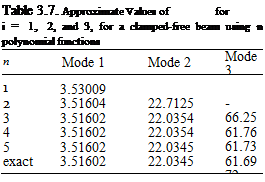
The fact that the governing equation is derivable from energy is reflected in the symmetry of [M] and [K]. Results for free vibration (i. e., with f = 0) are given in Table 3.7. As with the Ritz method, we see monotonic convergence from above and accuracy comparable to that achieved via the Ritz method. However, unlike the Ritz method, we do not always obtain results for free-vibration problems that converge from above.

Galerkin’s Method Galerkin’s Method Подпись: dz = 0 Подпись: (3.329)

Example: Galerkin’s Method for a Beam in Bending Using an Alternative Form of the Equation of Motion. Consider again a clamped-free beam. To obtain an alternative equation of motion, we integrate the equation of motion twice and use the boundary conditions of zero shear and bending moment to obtain an integro – partial differential equation

where z is a dummy variable. Although this equation of motion is somewhat more complicated, it is only a second-order equation. Thus, it has only two boundary conditions, which are zero displacement and slope at x = 0. Thus, a much simpler

Подпись:
set of comparison functions can be used, such as a simple power series; that is

Фі = (-) i = 1,2,…,n (3.330)

We should not expect greater accuracy from this simple set of functions, but the analytical effort is considerably less. Indeed, the elements of the stiffness matrix are

Подпись: (3.331)Подпись:Kij = f БІфі Ф"dx J0

EIj( j +1) t(i +j +1)

and the elements of the mass matrix are

p t p t

Mij = ф, (Z – х^фj (Z )dZ dx

J0 Jx

mt3

(2 +i )(3 + i )(5 + i + j)

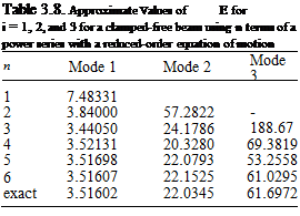
Note that these matrices are not symmetric. Moreover, the results presented in Table 3.8 are not as accurate as those obtained in Table 3.7, and the convergence is not monotonic from above.

The partial differential equations derived previously for free vibration of strings, beams in torsion, and beams in bending can be derived from energy-based ap­proaches, such as Hamilton’s principle. (The use of Hamilton’s principle is beyond the scope of this text, but detailed treatments are found in numerous graduate-level texts on structural dynamics.) In those cases, the Ritz and Galerkin’s methods give the same results when used with the same approximating functions. As shown here, however, Galerkin’s method provides a viable alternative to the Ritz method in cases where the equations of motion are not of the form presented previously in this chapter.

Подпись: '/////
Figure 3.44. Schematic of a nonuniform beam with distributed twisting moment per unit length

Approximate Solution Techniques

There are several popular methods that make use of a set of modes or other functions to approximate the dynamic behavior of systems. In this section, without going into detail about the theories associated with this subject, we illustrate within the framework already established how we can use a truncated set of modes or another set of functions to obtain an approximate solution. Details of the theories behind modal approximation methods are found in texts that treat structural dynamics at the graduate level. The two main approaches are (1) Galerkin’s method, applied to ordinary or partial differential equations; and (2) the Ritz method, applied to Lagrange’s equations or the principle of virtual work. These two methods yield identical results in certain situations. Thus, if time is limited, it would be necessary to discuss only one of the two methods to give students an introduction to the method and an appreciation of results that can be obtained this way. The Ritz method is preferred in the present context because of the ease with which it can be presented within the framework of Lagrange’s equations. Nevertheless, both of these methods are presented at a level suitable for undergraduate students.

3.5.1 The Ritz Method

Подпись: d / d L ' d L dt  d^i J d^i Подпись: i = 1, 2,.. .,n Подпись: (3.294)

Building on the previous treatment, we start with Lagrange’s equations, given by

where in the Lagrangean, L = K – P, the total kinetic energy is K, the total potential energy is P, n is the number of generalized coordinates retained, the generalized coordinates are ^, and Ei is the generalized force. Although it can be helpful, as discussed herein, it is not necessary to make use of potential energy, which can account only for conservative forces. The generalized force, however, can be used to include the effects of any loads. So as not to count the same physical effects more than once, the generalized force should include only those forces that are not accounted for in the potential energy. The generalized forces stem from virtual work, which can be written as

n

SW =J2 Eis& (3.295)

i =1

where S& is an arbitrary increment in the ith generalized coordinate.

Consider a beam in bending as an example. The total kinetic energy must include that of the beam as well as any attached particles or rigid bodies. The contribution

(3.296)

Подпись: K -‘'•beam Approximate Solution Techniques

Подпись: of the beam is

where m is the mass per unit length of the beam. The total potential energy P = U + V comprises the internal strain energy of the beam, denoted by U, plus any additional potential energy, V, attributed to gravity, springs attached to the beam, or applied static loads. All other loads, such as aerodynamic loads, damping, and follower forces, must be accounted for in Ei.

Подпись: и=2 Подпись: (3.297)
Approximate Solution Techniques

The strain energy for a beam in bending is given by

The expression for V varies depending on the problem being addressed, as does the virtual work of all forces other than those accounted for in V. The virtual work of an applied distributed force per unit length f (x, t) can be written as

SW = f f(x, t)8v(x, t)dx (3.298)

J0

where Sv is an increment of v in which time is held fixed and f (x, t) is positive in the direction of positive v.

To apply the Ritz method, we need to express P, K, and S W in terms of a series of functions with one or more terms. For a beam in bending, this means that

n

Подпись: (3.299)v(x, t) = J2 Si (t)Фі (x)

i=1

There are several characteristics that these “basis functions” фі must possess, as follows: [3] [4] [5]

Examples of complete sets of functions on the interval 0 < x < £ include

1, x, x2,…

Подпись: sin. /П x (2nx . (3nx

sm( ~) ’ sm ~) ’ sin ~T

a set of mode shapes for any problem

Completeness also implies that there can be no missing terms between the lowest and highest terms used in any series.

4. The set of functions must be linearly independent. This means that

n

Подпись:ai фі (x) = 0 ^ at = 0 for all і

i=0

A set of functions that satisfies all of these criteria is said to be “admissible.”

By use of the series approximation, we reduced a problem with an infinite number of degrees of freedom to one with n degrees of freedom. Instead of being governed by a partial differential equation, the behavior of this system is now defined by n second-order, ordinary differential equations in time. This reduction from a continuous system modeled by a partial differential equation with an infinite number of degrees of freedom to a system described by a finite number of ordinary differential equations in time is sometimes called spatial discretization. The number n is usually increased until convergence is obtained. (Note that if inertial forces are not considered so that the kinetic energy is identically zero, then a system described by an ordinary differential equation in a single spatial variable is reduced by the Ritz method to a system described by n algebraic equations.)

Now, let us illustrate how the approximating functions are actually used. Let фі, і = 1,2,…, ж, be a complete set of p-times differentiable, linearly independent functions that satisfy the displacement and rotation boundary conditions. Thus, U can be written as

Подпись: і =1 j = 1 (3.301)

The contributions of any springs that restrain the structure, as well as conservative loads, must be added to obtain the full potential energy P.

The kinetic energy of the beam is

Подпись: і =1 j=1 (3.302)

Contributions of any additional particles and rigid bodies must be added to obtain the complete kinetic energy K.

The virtual work must account for distributed and concentrated forces resulting from all other sources, such as damping and aerodynamics. This can be written as

Approximate Solution Techniques(3.303)

where x0 is a value of x at which a concentrated force is located. Here, the first term accounts for a distributed force f (x, t) on the interior of the beam, and the second term accounts for a concentrated force on the interior (see Eq. 3.96). In aeroelasticity, the loads f (x, t) and Fc(x0, t) may depend on the displacement in a complicated manner.

The integrands in these quantities all involve the basis functions and their deriva­tives over the length of the beam. Note that these integrals involve only known quan­tities and often can be evaluated analytically. Sometimes they are too complicated to undertake analytically, however, and they must be evaluated numerically. Numeri­cal evaluation is often facilitated by nondimensionalization. Symbolic computation tools such as MathematicaTM and MapleTM may be helpful in both situations.

With all such things considered, the equations of motion can be written in a form that is quite common; viz.

Подпись: (3.304)[M] {f} + [C] {1} + [K] (f } = {F}

where (f} is a column matrix of the generalized coordinates, {F} is a column matrix of the generalized force terms that do not depend on f, () is the time derivative of (), [M] is the mass matrix, [C] is the gyroscopic/damping matrix, and [K] is the stiffness matrix. The most important contribution to [M] is from the kinetic energy, and this contribution is symmetric. The most important contribution to [K] is from the strain energy of the structure and potential energy of any springs that restrain the motion of the structure. There can be contributions to all terms in the equations of motion from kinetic energy and virtual work. For example, there are contributions from kinetic energy to [C] and [K] when there is a rotating coordinate system. Damping makes contributions to [C] through the virtual work. Finally, because aerodynamic loads, in general, depend on the displacement and its time derivatives, aeroelastic analyses may contain terms in [M], [C], and [K] that stem from aerodynamic loads.

An interesting special case of this method occurs when the system is conser­vatively loaded. The resulting method is usually referred to as the Rayleigh-Ritz method, and many theorems can be proved about the convergence of approxima­tions to the natural frequency. Indeed, one of the most powerful of such theorems states that the approximate natural frequencies are always upper bounds; another states that adding more terms to a given series always lowers the approximate natural frequencies (i. e., making them closer to the exact values).

A further specialized case is the simplest approximation, in which only one term is used. Then, an approximate expression for the lowest natural frequency can be written as a ratio called the “Rayleigh quotient.” This simplest special case is of more than merely academic interest: It is not at all uncommon that a rough estimate of the lowest natural frequency is needed early in the design of flexible structures.

Example: The Ritz Method Using Clamped-Free Modes. In the first example, we consider a uniform, clamped-free beam that we modify by adding a tip mass of mass цті. The exact solution can be obtained easily for this modified problem using the methodology described previously. However, it is desired here to illustrate the Ritz method, and we already calculated the modes for a clamped-free beam (i. e., without a tip mass) in Section 3.3.4. These mode shapes are solutions of an eigenvalue problem; therefore, provided we do not omit any modes between the lowest and highest mode number that we use, this set is automatically complete. The set is also orthogonal and therefore linearly independent. Of course, these modes automatically satisfy the boundary conditions on displacement and rotation for our modified problem (because they are the same as for the clamped-free beam), and they are infinitely differentiable. Hence, they are admissible functions for the modified problem. Moreover, they satisfy the condition of zero moment at the free end, which is a boundary condition for our modified problem. However, because of the presence of the tip mass in the modified problem, the shear force—which readers will recall is proportional to the third derivative of the displacement—does not vanish as it does for clamped-free mode shapes.

The strain energy becomes

1 n n г

U = – £ J2 &&j ЕІф-ф’-dx (3.305)

2 t- j=i J°

Approximate Solution Techniques Подпись: (3.306)

Substituting the mode shapes of Eq. (3.258) into Eq. (3.305) and taking advantage of orthogonality, we can simplify it to

Подпись: Kp Approximate Solution Techniques Подпись: (3.307)

where ai is the set of constants in Table 3.1. Similarly, accounting for the tip mass, the kinetic energy of which is

we obtain the total kinetic energy as

Подпись: 1Подпись: 2Подпись: тфі ф jdx + ілт!фі (г)ф j (г)Approximate Solution Techniques(3.308)

Approximate Solution Techniques Подпись: (3.309)

With the use of the mode shapes in Eq. (3.258), we find that фі (г) = 2(-1)i+1; therefore, the kinetic energy simplifies to

i=1 j=1

Table 3.3. Approximate values of =■ for

clamped-free beam with tip mass of ftml using n clamped-free modes of Section 3.3.4, Eq. (3.258)

n

lx = 1

ft = 10

Х = 100

1

1.57241

0.549109

0.175581

2

1.55964

0.542566

0.173398

3

1.55803

0.541748

0.173126

4

1.55761

0.541536

0.173055

5

1.55746

0.541458

0.173029

Exact

1.55730

0.541375

0.173001

where the Kronecker symbol Sij = lfori = j and Stj = Ofori = j. For free vibration, there are no additional forces. Thus, Lagrange’s equations now can be written in matrix form as

[M] {!} + [tf] {f} = 0 (3.310)

where [‘tf’] is a diagonal matrix with the diagonal elements given by

KH = Ellaf i = 1,2,…,n (3.311)

and [M] is a symmetric matrix with elements given by

Mij = ml [Sij + 4д(-1)+j ] i, j = 1, 2,…,n (3.312)

Assuming f = f exp(iat), we can write Eq. (3.310) as an eigenvalue problem of the form

[[tf] – m2[M]] {f} = 0 (3.313)

Results for the first modal frequency are shown in Table 3.3 and compared therein with the exact solution. As we can see, the approximate solution agrees with the exact solution to within engineering accuracy with only two terms. For contrast, results for the second modal frequency are shown in Table 3.4; these results are not nearly as accurate. Results for the higher modes (not shown) are even less accurate. This is one of the problems with modal-approximation methods; fortunately, however,

Table 3.4. Approximate values of?= for

clamped-free beam with tip mass of p. ml using n clamped-free modes of Section 3.3.4, Eq. (3.258)

n

ft = 1

ft = 10

Х = 100

2

16.5580

15.8657

15.7867

3

16.3437

15.6191

15.5367

4

16.2902

15.5576

15.4744

5

16.2708

15.5353

15.4518

Exact

16.2501

15.5115

15.4277

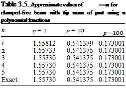
Подпись: Table 3.5. Approximate values of ==■ for clamped-free beam with tip mass of pmt using n polynomial functions n p = 1 p = 10 p = 100 1 1.55812 0.541379 0.173001 2 1.55733 0.541375 0.173001 3 1.55730 0.541375 0.173001 4 1.55730 0.541375 0.173001 5 1.55730 0.541375 0.173001 Exact 1.55730 0.541375 0.173001

aeroelasticians and structural dynamicists frequently are interested in only the lower – frequency modes. Note that the one-term approximation (i. e., the Rayleigh quotient) is within 1.1% for all values of p displayed.

Example: The Ritz Method Using a Simple Power Series. As an alternative to using the mode shapes of a closely related problem, let us repeat the previous solution using a simple power series to construct a series of functions Фі. Because the moment vanishes at the free end where x = t, we can make the second derivative of all terms proportional to t – x. To obtain a complete series, we can multiply this term by a complete power series 1, x, x2, and so on. Thus, we then may write the second derivative of the ith function as

Подпись: Ф'І(3.314)

Подпись: ФІ Подпись: (t)'+1 [2 + i - i(l)] i (1 + i) (2 + i) Подпись: (3.315)

With the boundary conditions on displacement and rotation being фі (0) = ф[ (0) = 0, we then can integrate to find an expression for the ith function as

Because the chosen admissible functions have nonzero third derivatives at the tip, they offer the possibility of satisfying the nonzero shear condition in combination with one another. Such admissible functions are sometimes called “quasi-comparison functions.”

Подпись: K.. = 2E ’ p(i +j -1) (i +j)(1 +i +j) Подпись: i, j = 1, 2, ...,n Подпись: (3.316)

In this case, the stiffness matrix becomes

Approximate Solution Techniques Подпись: (3.317)

and the mass matrix

Results from this calculation are given in Tables 3.5 and 3.6 for the first two modes. It is clear that these results are much better than those obtained with the

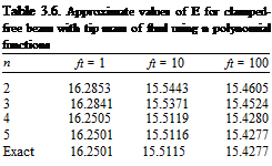
Подпись: Table 3.6. Approximate values of E for clamped-free beam with tip mass of ftml using n polynomial functions n ft = 1 ft = 10 ft = 100 2 16.2853 15.5443 15.4605 3 16.2841 15.5371 15.4524 4 16.2505 15.5119 15.4280 5 16.2501 15.5116 15.4277 Exact 16.2501 15.5115 15.4277

clamped-free beam modes. It is not unusual for polynomial functions to provide better results than those obtained with beam mode shapes. However, here it is worth noting that the beam mode shapes are at a disadvantage for this problem. Unlike the problem being solved (and the polynomials chosen), the beam mode shapes are constrained to have zero shear force at the free end and thus are not quasi­comparison functions for the problem with a tip mass. This one-term polynomial approximation (i. e., the Rayleigh quotient) is within 0.05%, which is exceptionally good given its simplicity.

It is sometimes suggested that the mode shapes of a closely related problem are—at least, in some sense—superior to other approximate sets of functions. For example, in the first example, we saw that the orthogonality of the modes used re­sulted in a diagonal stiffness matrix, which provides a slight advantage in the ease of computing the eigenvalues. However, for the low-order problems of the sort we are discussing, that advantage is hardly noticeable. Indeed, symbolic computation tools such as MathematicaTM and MapleTM are capable of calculating the eigenvalues for problems of the size of this example in but a few seconds. Moreover, in some cases, the simplicity of carrying out the integrals that result in approximate formulations is a more important factor in deciding which set of functions to use in a standard im­plementation of the Ritz method. Indeed, polynomial functions are generally much easier to deal with analytically than free-vibration modes such as those illustrated in Section 3.5.1, which frequently involve transcendental functions.

Alternatives to the standard Ritz method include the methods of Galerkin, fi­nite elements, component mode synthesis, flexibility influence coefficients, methods of weighted residuals, collocation methods, and integral equation methods. We in­troduce Galerkin’s method and the finite element method in the next two sections. Detailed descriptions of other approaches are found in more advanced texts on structural dynamics and aeroelasticity.

Boundary Conditions

The boundary conditions for coupled bending and torsion range from very simple to somewhat complex, depending on the type of restraint(s) imposed on the ends. For example, for a clamped end, we have v = dv/dx = в = 0, the same as for uncoupled bending and torsion. Similarly, a free end has zero bending moment, shear force, and twisting moment, respectively written as M = V = T = 0. Note the definitions of M and T in Eqs. (2.58) and that V = – BM/дx. Equations governing other re­straints may be determined by appropriate kinematical or physical relationships. For example, a pinned connection may imply specification of an axis about which the moment vector (i. e., combination of bending and twisting moments) vanishes and perpendicular to which components of the rotation vector (i. e., combination of bending and twisting rotations) vanish. Relationships for both elastic and inertial restraints may be developed using Euler’s laws, as in the uncoupled cases herein.

The complexity of this class of problem provides excellent motivation for the introduction of approximate methods, which is undertaken in the next section.

Calculation of Forced Response

The formulation of initial-value problems for beams in bending is almost identical to that for beams in torsion and for strings; see Sections 3.1.7 and 3.2.4, respectively. We should first determine the virtual work done by the applied loads, such as a distributed transverse force per unit length. From this, we may find the generalized forces associated with bending. Once they are known, one may solve the generalized equations of motion, which are in the form of Eq. (3.90). The resulting initial – value problem then can be solved by invoking orthogonality to obtain values of the arbitrary constants in the general and particular solutions, as illustrated in the examples in Section 3.1.7.

3.4 Free Vibration of Beams in Coupled Bending and Torsion

In this section, the analytical treatment of coupled bending-torsion vibration of composite beams is briefly considered. The treatment is restricted to uniform beams and to the presentation of governing equations, sample boundary conditions, and suggestions for solution.

3.4.1 Equations of Motion

Calculation of Forced Response Подпись: (3.287)

First, we specialize Eqs. (2.65) for spanwise uniformity and free vibration, yielding

Calculation of Forced Response Calculation of Forced Response

Because these are linear equations with constant coefficients, for free vibration we may assume simple harmonic motion. In the spirit of separation of variables, the solutions for v and в are written as

For there to be a nontrivial solution, the determinant of the coefficient matrix must vanish, yielding

(EI GJ — K2)a6 + pIp EIm2aA — mGJm2a2 — (mpIp — m2d2)m4 = 0 (3.291)

This cubic equation in a2 may be solved for arbitrary m2. When d and K are nonzero, finding the exact, closed-form solution “by hand” is problematic. However, with the aid of symbolic computational tools such as Mathematica™, we may easily extract the six roots denoted here by ai for i = 1, 2,…, 6, as functions of m2. Note that ai+3 = – ai for i = 1, 2, and 3.

Therefore, when K, d = 0, the solution for the mode shape may be written as

v = Ci exp(aix) + C2 exp(a2x) + C3 exp(a3x)

Подпись: (3.292)+ C4 exp(—aix) + C5 exp(—a2x) + C6 exp(—a3x) в = D exp(a! x) + D2 exp(a2x) + D3 exp(a3x)

+ D4 exp(—a1 x) + D5 exp(—a2x) + D6 exp(—a3x)

Подпись: Di = Ci Подпись: Kaf — md m2 GJ a2 + p Ipm2 Подпись: i = 1, 2,..., 6 Подпись: (3.293)

where

Now, with six boundary conditions (i. e., three at each end), we may find six homo­geneous algebraic equations for Ci. The condition for a nontrivial solution leads to the characteristic equation for m2

. There is a denumerably infinite set of roots for m2, so that for any value determined for m2, we may find any five of the Ci coefficients in terms of the sixth and thus determine the mode shapes. In general, each mode shape involves both v and в. For small couplings (i. e., such that K2 < GJ EI and md2 < pIp), one “branch” of these roots is near the uncoupled bending frequencies and the other is near the uncoupled torsional frequencies.

Example Solutions for Mode Shapes and Frequencies

In this section, we consider several examples of the calculation of natural frequencies and mode shapes of vibrating beams in bending. One of the simplest cases is the pinned-pinned case, with which we begin. It is one of the few cases for beams in bending for which a numerical solution of the characteristic equation is not required. Next, we treat the important clamped-free case, followed by the case of a hinged-free beam with a rotational restraint about the hinge. Finally, we consider the free-free case, illustrating the concept of the rigid-body mode.

Example Solution for Pinned-Pinned Beam. Consider the pinned-pinned beam as shown in Fig. 3.35. The horizontal rollers at the right end are placed there to indicate that the resultant axial force in the beam is zero. Otherwise, the problem becomes highly nonlinear because it then becomes necessary to take the axial force into account, thereby significantly complicating the problem! The boundary conditions reduce to conditions on X given by

<————————– Є—————————- ►

——————— >-x

Example Solutions for Mode Shapes and Frequencies

Figure 3.35. Schematic of pinned-pinned beam


Substituting the first two boundary conditions into the general solution as found in Eq. (3.205), we find that

Подпись:A + A = 0

a2(- A + D4) = 0

Recall that the constant a cannot be zero. To consider the a = 0 case we must take a solution in the form of a cubic polynomial, and the boundary conditions for this case do not yield a nontrivial solution of that form. Therefore, D2 = D4 = 0, and the solution for X becomes

X(x) = Di sin(ax) + A sinh(a x) (3.242)

Подпись: sin(a£) sinh(a£) D1 -sin(a£) sinh(a£) D3 Подпись: 0 0 Подпись: (3.243)

Using the last two of the boundary conditions, we obtain a set of homogeneous algebraic equations in D1 and D3

A nontrivial solution can exist only if the determinant of the coefficients is equal to zero;therefore

2sin(a£) sinh(a£) = 0 (3.244)

Because a = 0, we know that the only way this characteristic equation can be satisfied is for

Подпись:sin(a£) = 0

Example Solutions for Mode Shapes and Frequencies Подпись: (3.246)

which has a denumerably infinite set of roots given by

Although this is the same set of eigenvalues that we found for the string problem, the relationship to the natural frequencies is quite different; viz.

Подпись: m

EIaa (3.247)

Example Solutions for Mode Shapes and Frequencies

Example Solutions for Mode Shapes and Frequencies

Figure 3.36. Schematic of clamped-free beam


As observed in the cases of the string and beam torsion, there is associated with the ith natural frequency a unique deformation shape called the mode shape (or eigenfunction). Each mode shape can be obtained from the spatially dependent portion of the solution by evaluating the function, X, (x), for any known value of a,. To find X, we substitute any value for a, back into either of the two scalar equations represented by the matrix equation in Eq. (3.243). It is important to recognize that the constants D1 and D now should be written as D1i and A,. Using the first of these equations along with the knowledge that sinh(a, l) = 0, we find that D3, = 0, leaving

Xi = Du sin (^ (i = 1, 2,…) (3.249)

where D1i can be any nonzero constant. For example, choosing D1i = 1, we find the mode shape to be

Фі = sin I (i = 1,2,…) (3.250)

which is the same mode shape as obtained previously for the vibrating string.

Example Solution for Clamped-Free Beam. Consider the clamped-free beam as shown in Fig. 3.36, the boundary conditions of which reduce to conditions on X given by

X(0) = X ‘(0) = X "(l) = X "'(l) = 0 (3.251)

As in the previous example, we can show that this problem does not exhibit a nontrivial solution for the case of a = 0. Thus, we use the form of the general solution in Eq. (3.206) for which a = 0. Along with the first two boundary conditions, this yields

Подпись: (3.252)X(0) = 0 ^ E3 = 0 X'(0) = 0 ^ E1 = 0

The remaining boundary conditions yield two homogeneous algebraic equations that may be reduced to the form

Подпись: 0 0 Подпись: (3.253)sinh(al) + sin(al) cosh(al) + cos(al)

cosh(al) + cos(al) sinh(al) – sin(al)

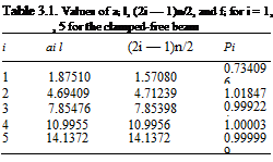
Подпись: Table 3.1. Values of ai l, (2i — 1)n/2, and fi for i = 1, , 5 for the clamped-free beam i ai l (2i — 1)n/2 Pi 1 1.87510 1.57080 0.734096 2 4.69409 4.71239 1.01847 3 7.85476 7.85398 0.999224 4 10.9955 10.9956 1.00003 5 14.1372 14.1372 0.999999

It can be verified by applying Cramer’s method for their solution that a nontrivial solution exists only if the determinant of the coefficients is equal to zero. This is typical of all nontrivial solutions to homogeneous, linear, algebraic equations, and here yields

sinh2(al) — sin2(al) — [cosh(al) + cos(al)]2 = 0 (3.254)

or, noting the identities

Подпись:sin2(al) + cos2(al) = 1

cosh2(al) — sinh2(al) = 1

we obtain the characteristic equation as simply

cos(al) cosh(al) + 1 = 0

Подпись: (ai l)2 Подпись: EI ml,4 Подпись: (3.257)

We cannot extract a closed-form exact solution for this transcendental equation. However, numerical solutions are obtained easily. Most numerical procedures re­quire initial estimates of the solution to converge. Because cosh(al) becomes large as its argument becomes large, we can argue that at least the largest roots will be close to those of cos(al) = 0, or ail = (2i — 1)n/2. Indeed, the use of these values as initial estimates yields a set of numerical values that approach the initial estimates ever more closely as i increases. The values of ail (i. e., dimensionless quantities) are listed in Table 3.1. To six places, all values of atl for i > 5 are equal to (2i — 1)n/2. The corresponding natural frequencies are given by

To obtain the mode shapes, we substitute the values in Table 3.1 into either of Eqs. (3.253). The resulting equation for the ith mode has one arbitrary constant remaining (i. e., either E2i or E4i can be kept), which can be set equal to any number desired to conveniently normalize the resulting mode shape фі. For example, nor­malizing the solution by — E4i, which is equivalent to setting E4i = -1, we can show that

Подпись:фі = cosh(aix) — cos(aix) — в [sinh(aix) — sin(aix)]

E2i cosh(a, l) + cos(a, l)

Подпись:

Example Solutions for Mode Shapes and Frequencies Подпись: X 7

Подпись:Подпись: X 7 Example Solutions for Mode Shapes and Frequencies

Example Solutions for Mode Shapes and Frequencies Example Solutions for Mode Shapes and Frequencies
Подпись: Figure 3.37. First three free-vibration mode shapes of a clamped-free beam in bending

E4i sinh(a, l) + sin(a, l)

Example Solutions for Mode Shapes and Frequencies Подпись: (3.260)

The values of в also are tabulated in Table 3.1. For this particular normalization

фі (l) = 2(—1)’+1

the first of which is left to the reader to show (see Prob. 10d). The first three mode shapes are depicted in Fig. 3.37. Note that as with previous results, the higher the mode number, the more nodes (i. e., crossings of the zero-displacement line).

Example Solution for Spring-Restrained, Hinged-Free Beam. This sample prob­lem for which modes of vibration are determined is for a uniform beam that is hinged at the right-hand end and restrained there by a rotational spring with elastic

Figure 3.38. Schematic of spring-restrained, hinged-free beam

Подпись: x=Q x=i constant к = кEI/l. The left-hand end is free, as illustrated in Fig. 3.38. The bound­ary conditions for this case require that
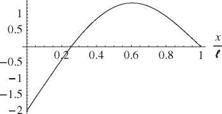
X"(0) = 0 X //7(0) = 0 X(l) = 0

EIX"(l) = – kX'(l) or lX"(l) = – кX'(l)

The spatially dependent portion of the general solution is used in the form of Eq. (3.206). The two conditions of zero bending moment and shear at x = 0 re­quire that

Подпись: (3.262)X"(0) = 0 ^ E4 = 0 X’"(0) = 0 ^ E2 = 0

The third boundary condition, that of zero displacement at x = l, can now be indi­cated by

X(l) = E1 [sin(al) + sinh(al)] + E3 [cos(al) + cosh(al)] = 0 (3.263)

The fourth boundary condition, a rotational elastic constraint at x = l, can be written as

l2 X"(l) + KlX'(l) = 0 (3.264)

so that

(al)2 {E1 [-sin(al) + sinh(al)] + E3 [-cos(al) + cosh(al)]}

+ Kal{ E1 [cos(al) + cosh(al)] + E3 [-sin(al) + sinh(al)]} = 0 This relationship can be rearranged as

{

al 1

cos(al) + cosh(al) +—– [-sin(al) + sinh(al)]

K (3.266)

al

+ E3 – sin(al) + sinh(al) + – [- cos(al) + cosh(al)] = 0

The simultaneous solution of Eqs. (3.263) and (3.266) for nonzero values of E1 and E3 requires that the determinant of the 2×2 array formed by their coefficients must
be zero. Setting the determinant formed from Eqs. (3.263) and (3.266) to zero, we find

{al

sin(al) – sinh(al) +—— [cos(al) – cosh(al)]

к

{

al cos(al) + cosh(al) +—- [- sin(al) + sinh(al)H = 0

(3.267)

After executing the indicated multiplications and applying the identities of Eqs. (3.255), the relationship becomes

Example Solutions for Mode Shapes and Frequencies^ [sin(al) cosh(al) – cos(al) sinh(al)] = 1 + cos(al) cosh(al) (3.268)

This is the characteristic equation. As in the previous example, it is a transcendental equation that cannot be solved analytically. Note that for specified finite and nonzero values of к, we may calculate numerically a denumerably infinite set of the eigen­values at l (for i = 1, 2,…) by a suitable iterative procedure. For such an iterative solution, we need initial estimates for the als. Note, however, that this equation is a special case in which we may solve for к as a function of al without iteration.

In the limit as к tends to infinity, we find eigenvalues in agreement with the clamped-free case, as expected. In the limit as к tends to zero, we can show that a rigid-body mode exists. The next example illustrates a procedure by which we may prove the existence of one or more rigid-body modes. It is important to note, however, that it is incorrect to try to infer the existence of a rigid-body mode because al = 0 satisfies Eq. (3.268) in the limit as к tends to zero; our general solution for X is valid only when a = 0.

Подпись: Mi = ai л — m Подпись: (at l)2 Подпись: EI ml4 Подпись: (i = 1, 2,...) Подпись: (3.269)

For specified values of m, EI, l, and the stiffness parameter к, the eigenvalues can be used to determine the natural frequencies as

Подпись: ФІ (x) Подпись: X (x) Eu Подпись: (3.270)

and the ith mode shape can be defined as

= sin(atx) + sinh(atx) + ві [cos(atx) + cosh(atx)]

Подпись: The modal parameter Д boundary condition at x becomesПодпись:E3i /Eui can be obtained from the zero-displacement l, Eq. (3.263). When evaluated for the ith mode, Д

E3i = sin(q; l) + sinh(q; l) (3

Eui cos(ai l) + cosh(ai l) ‘ numerical values of which can be found once ai l is known for specific values of к.

A sample set of numerical results for this example is shown in Figs. 3.39 through 3.41. The first three mode shapes are shown for к = 1 in Fig. 3.39. Fig. 3.40 shows the variation of ai l versus к for i = 1, 2, and 3, illustrating the fact that the frequencies of

Figure 3.39. Mode shapes for first three modes of a spring-restrained, hinged-free beam in bending; к = 1,

Example Solutions for Mode Shapes and Frequencies

Подпись: Фг Example Solutions for Mode Shapes and Frequencies

«1 = (1.24792)^/~Ш/(тЄ4), on =

Подпись: <h

(4.03114)2^jEfJ(mt4), and o3 = (7.13413)^/El/(mS4)

the higher modes are much less sensitive to the spring constant than that of the first mode. Indeed, the first mode frequency (proportional to the square of the smallest plotted quantity in Fig. 3.40) tends to zero as к tends toward zero in the limit. This can be interpreted as the lowest-frequency mode transitioning to a rigid-body mode, which exists only when the spring constant is identically zero. In the limit as к becomes infinite, in contrast, the eigenvalues tend toward those of the clamped-free beam, as expected. Indeed, as Fig. 3.41 shows, when к = 50 the mode shape starts

Подпись: Oi( Figure 3.40. Variation of lowest eigenvalues at I ver­sus dimensionless spring constant к

X

Подпись: Ф і (

Figure 3.41. Mode shape for fundamental mode of the spring-restrained, hinged – free beam in bending; к = 50, м1 =

(1.83929)2УElKmS4)

to look more like that of a clamped-free beam (with the fixity being on the right end in this example).

Example Solution for Free-Free Beam. The case of a uniform beam that is uncon­strained at both ends, Fig. 3.42, may be considered as a crude first approximation to a freely flying vehicle. Their elastic and rigid dynamic properties are quite similar. In both instances, these properties can be described in terms of a modal representation.

The boundary conditions for this case require that
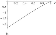
X "(0) = X "'(0) = X"(l) = X’"(l) = 0 (3.272)

The spatially dependent portion of the general solution to be used here again involves the sums and differences of the trigonometric and hyperbolic functions. Two of the E s can be eliminated by applying the boundary conditions at x = 0 so that

Подпись: (3.273)X"(0) = 0 ^ E4 = 0 X’"(0) = 0 ^ E2 = 0

The conditions at x = I of zero bending moment and zero shear X"(i) = 0, and X(£) = 0, respectively, yield the following relationships:

E1 [- sin(a£) + sinh(a£)] + E3 [- cos(a-f) + cosh(a-f)] = 0

(3.274)

E1 [- cos(a-f) + cosh(a-f)] + E3 [sin(a£) + sinh(a£)] = 0

Here again, the nontrivial solution to these equations requires that the determinant of the E1 and E3 coefficients be zero. This relationship becomes

sinh2(a£) – sin2(a£) – [cosh(a-f) – cos(a-f)]2 = 0 (3.275)

which simplifies to

Подпись: (3.276)cos(a-f) cosh(a-f) = 1

Подпись: Table 3.2. Values of ai l, (2i + 1)n/2, and в for i = 1, , 5 for the free-free beam i ai l (2i + 1)n/2 Pi 1 4.73004 4.71239 0.982502 2 7.85320 7.85398 1.00078 3 10.9956 10.9956 0.999966 4 14.1372 14.1372 1.00000 5 17.2788 17.2788 1.00000

For large al, the roots tend to values that make cos(al) = 0. Unlike the clamped-free case, however, there is no root near n/2, and the first nonzero root occurs near 3n/2. Indeed, the ith root is near (2i + 1)n/2. Thus, the roots of this characteristic equation readily can be computed numerically to yield the eigenvalues ai l in Table 3.2. From these numerical values, the natural frequencies can be found as

Подпись: Mi = ai(3.277)

Подпись: ФІ (x) Подпись: X (x) E3i Подпись: (3.278)

The mode shape associated with each eigenvalue can be defined as

= cos(aix) + cosh(aix) – в [sin(aix) + sinh(aix)]

The numerical value of the modal parameter в = – E1i / E3i, also tabulated in Ta­ble 3.2, can be obtained from either of the boundary conditions given in Eqs. (3.274). Using the first of those equations as an example, we obtain

Подпись: (3.279)E1i cosh(ail) – cos(ail)

E3i sinh(ail) – sin(ail)

It can be shown that the first of Eqs. (3.274) would yield the same result by using the characteristic equation as an identity. The first three of these mode shapes are shown in Fig. 3.43.

In addition to these modal properties that can be used to describe the elastic behavior of the beam, there are also modal properties that describe the rigid be­havior of the beam. These modes are associated with zero values of the separation constant a. Recall that a similar result was obtained for torsional deflections of a free-free beam. When a is zero, the governing ordinary differential equations for beam bending, Eqs. (3.197), become

Подпись: (3.280)X"" = 0 Y = 0

bx3

Example Solutions for Mode Shapes and Frequencies Подпись: (3.281)

The general solutions to these equations can be written as

Y = ft + g

Подпись: ФіПодпись:Подпись: XExample Solutions for Mode Shapes and Frequencies

Example Solutions for Mode Shapes and Frequencies Example Solutions for Mode Shapes and Frequencies

Figure 3.43. First three free-vibration elastic mode shapes of a free-free beam in bending

where the arbitrary constants, b through e, in the spatially dependent portion of the solution can be established from the boundary conditions. These conditions of zero bending moment and shear at the ends of the beam yield the following:

X "(0) = 0 ^ c = 0

X(0) = 0 ^ b = 0

(3.282)

X"(t) = 0 ^ b t + c = 0 X’"(l) = 0 ^ b = 0

It is apparent that all four boundary conditions can be satisfied with b = c = 0. Because no restrictions are placed on the constants d and e, they can be arbitrary. Thus, a general description of the solution in this case is

X = dx + e (3.283)

An important characteristic of this solution is that no relationship has been estab­lished between d and e. Therefore, they can be presumed to represent two inde­pendent motions of the beam. As written previously, e represents a rigid vertical translation of the beam because it is independent of x. The dx term, being linear
in x, represents a rigid rotation of the beam about the left end. It can be shown that when the rotational motion is taken to be about the mass centroid, it and the translation are orthogonal with respect to one another and with respect to the elastic modes. This suggests that the modal representation for these rigid-body degrees of freedom can be described by

0

Подпись: (3.284)vrigid = У ‘ фі (x)fi(t)

І =—1

where

ф-1 = 1 and ^—1(t) = translation

t (3.285)

ф0 = x – 2 and %0(t) = rotation angle

The time-dependent portion of the solution for these rigid-body motions is seen to be aperiodic. This means that natural frequencies for both rigid-body modes are zero. The two arbitrary constants contained in Y(t) can be evaluated from the initial rigid-body displacement and velocity associated with the translation and rotation. Thus, the complete solution for the free-free beam-bending problem can now be written in terms of all of its modes as

TO

v =J2 Фі (x)ii (t) (3.286)

І = —1

This example provides a convenient vehicle for further discussion of symmetry. It was already noted in the case of a vibrating string that systems exhibiting geo­metric symmetry have two distinct types of mode shapes—namely, those that are symmetric about the midpoint and those that are antisymmetric about the midpoint. As can be seen in the results, this is indeed true for the modes of the free-free beam. In particular, the rigid-body translation mode and the first and third elastic modes are clearly symmetric about the midpoint of the beam, whereas the rigid-body rota­tion mode and the second elastic mode are antisymmetric about the midpoint (see Fig. 3.43).

This observation suggests that the symmetric mode shapes could be obtained by calculating the mode shapes of a beam that is half the length of the original beam and that has the sliding condition at one end and is free at the other. Similarly, the antisymmetric modes could be obtained by calculating the mode shapes of a beam with half the length of the original beam and that has one end pinned and the other free. It also should be evident that a symmetric aircraft with high-aspect-ratio wings, modeled as beams and attached to a rigid-body fuselage, could be represented similarly in terms of the symmetric and antisymmetric modes of the combined body and wing system. That is, we may model the whole system by considering only one wing attached to a rigid body with half the mass and half the rotational inertia with appropriate boundary conditions.

Boundary Conditions

For the beam-bending problem, it is necessary to impose two boundary conditions at each end of the beam. Mathematically, boundary conditions may affect v and its partial derivatives, such as dv/dx, d2v/3×2, d3v/3×3, d2v/3t2, and d3v/3xdt2. In the context of the separation of variables, these conditions lead to corresponding con­straints on some or all of the following at the ends: X, X’, X", and X"’. The resulting four boundary conditions on X and its derivatives are necessary and sufficient for determination of the four constants Ci, Di, or Ei (i = 1, 2, 3, and 4) to within a multiplicative constant.

As with torsion, the nature of the boundary conditions at an end stems from how that end is restrained. When an end cross section is unrestrained, the tractions on it are identically zero. Again, the most stringent condition is a perfect clamp, which for bending allows neither translation nor rotation of an end cross section. Like the clamped-end condition in torsion, the clamped end in bending is a common idealization, although nearly impossible to achieve in practice.

For the bending problem, a wide variety of cases that only partially restrain an end cross section is possible. The cases typically involve elastic and/or inertial reactions. A boundary condition that is idealized in terms of both translational and rotational springs may be used to more realistically account for support flexibility. Appropriate values for both translational and rotational flexibility of the support can be estimated from static tests. Finally, we can use rigid bodies and springs in combination to model attached hardware such as fuel tanks, engines, armaments, and laboratory fixtures.

Figure 3.25. Schematic of pinned-end condition

Boundary ConditionsIn this section, we consider the four “primitive” boundary conditions; four de­rived boundary conditions involving individual elastic and inertial restraints; and two examples of derived boundary conditions that involve combinations of v and its partial derivatives that can be imposed at the ends of the beam for determination of the four arbitrary constants of the general solution for X.

Boundary Conditions

A boundary condition can be written as a linear relationship involving one or more of the following: the beam deflection, its first three spatial partial derivatives, and its first two temporal partial derivatives. Although it is not a mathematical requirement, the particular combination of conditions to be specified at a beam end should represent a physically realizable constraint. The various spatial partial derivatives of the beam deflection can be associated with particular beam states at any arbitrary point along the beam. There are four such states of practical interest:

When relating these beam states, the positive convention for deflection and slope is the same at both ends of the beam. In contrast, the sign conventions on shear and bending moment differ at opposite beam ends, as illustrated by the free-body differential beam element used to obtain the equation of motion (see Fig. 2.6).

The most common conditions that can occur at the beam ends involve vanish­ing pairs of individual states. Typical of such conditions are the following classical configurations (specialized for spanwise uniformity):

• Clamped or built-in end, which implies zero deflection and slope, is illustrated in Fig. 3.10 and has v(£, t) = dv(£, t) = 0 so that X(£) = X'(£) = 0.

• Free end, which corresponds to zero bending moment and shear, is illustrated in Fig. 3.11 and has M(£, t) = V(£, t) = 0 so that X"(£) = X’"(£) = 0.

• Simply supported, hinged, or pinned end, which indicates zero deflection and bending moment, is denoted by the triangular symbol in Fig. 3.25 and has v(£, t) = M(£, t) = 0 so that X(£) = X"(£) = 0.

• Sliding end, which corresponds to zero shear and slope, is illustrated in Fig. 3.26 and has dv(£, t) = V(£, t) = 0 so that X'(£) = X’"(£) = 0.

All of these conditions can occur in the same form at x = 0.

Figure 3.26. Schematic of sliding-end condition

Boundary ConditionsIn addition to these zero-state conditions, we derive boundary conditions corre­sponding to linear-constraint reactions associated with elastic and inertial elements. The simplest of these are of the following four basic types:

• translational elastic constraint

• rotational elastic constraint

• translational inertia constraint

• rotational inertia constraint

Two additional examples are presented that are more involved because they entail combinations of these four types.

Translational Elastic Constraint. Consider a beam undergoing bending with a trans­lational spring with elastic constant к attached to the x = 0 end of a beam, as shown in Fig. 3.27. Assuming that this end of the beam is deflected by the amount v(0, t), then the spring tries to pull the end of the beam back to its original position by exerting a downward force at the end, the magnitude of which is equal to kv(0, t). Because the transverse-shear force at the left end (on the negative x face) is positive down, the boundary condition becomes

V(0, t) = kv(0, t) (3.207)

Using the definition of the shear force, we obtain

– Tx(E S)(at) = kv(0-‘) (3208)

To be useful for separation of variables, we must make the substitution v(x, t) = X(x)Y(t), yielding

[E7(0) X(0)7 = – kX(0) (3.209)

kv(0,t)

Подпись:(b) beam with spring force

Figure 3.27. Example beam undergoing bending with a spring at the x = 0 end

x=0 x=l

Подпись: Figure 3.28. Schematic of beam with translational spring at both ends

к——————— £——————— *

which further simplifies for a spanwise uniform beam to

E7X" (0) = – kX(0) (3.210)

If the spring were at x = I instead, the direction of the spring force at x = I would be the same (i. e., downward), but the shear force is positive upward because this is the positive x face. Thus

V(l, t) = – kv(l, t) (3.211)

and

[E7(l) X(l)"Y = kX(t) (3.212)

which further simplifies for a spanwise uniform beam to

~E7X’"(l) = kX(l) (3.213)

These conditions must be augmented by one additional condition at each end because two are required. For example, consider a beam with translational springs at both ends, as shown in Fig. 3.28. At each end, the other conditions for this case would be that the bending moment is equal to zero.

Rotational Elastic Constraint. Consider now a beam with a rotational spring at the right end, as depicted in Fig. 3.29. For a rotation of the end cross-sectional plane of dv/dx at x = l, which is positive in the counterclockwise direction, the spring exerts a moment in the opposite direction (i. e., clockwise). Because the bending moment at the right end of the beam is positive in the counterclockwise direction, the boundary condition then becomes

dv

Подпись: (a) beam with spring Figure 3.29. Example of beam undergoing bending with a rotational spring at right end Boundary Conditions

M(l, t) = – k (l, t) (3.214)

к к

Boundary ConditionsBoundary Conditions.WYvWW’ W\\\

Figure 3.30. Schematic of beam with rotational springs at both ends

Using the definition of bending moment, we find

д 2v dv

EI ) = – k~*{u) (3-215)

The boundary condition on X then becomes

ElX”(l) = – kX'(l) (3.216)

As with the shear force, the sign convention on bending moment differs at the opposite end. Here, at the left end, the spring still exerts a clockwise moment; however, the bending moment is also positive in the clockwise direction. Thus, we may write

dv

M(0, t) = k — (0, t)

Подпись: (3.217)Подпись: (3.218)д X

ш S(0-t)=кд (0-t)

for the condition on v(x, t) and its partial derivatives and

ElX"(0) = kX’ (0)

for that on X(x) and its derivatives. As before, one more condition is required at each end. Consider, for example, a beam with rotational springs at both ends, shown in Fig. 3.30. Here, it is necessary to set the shear forces at both ends equal to zero.

Translational and Rotational Inertia Constraints. The translational inertia con­straint stems from the inertial reaction force associated with the translational motion of either a rigid body or a particle attached to an end of a beam. Similarly, the ro­tational inertia constraint results from the inertial reaction moment associated with rotational motion of a rigid body attached to an end of a beam.

Consider the beam shown in Fig. 3.31, to which is attached a rigid body of mass mc and mass moment of inertia about the mass center C equal to IC. The point C is located on the x axis at x = 0, and the beam is assumed to be undergoing bending deformation. The set of all contact forces exerted on the body by the beam can be replaced by a single force applied at the point C, and the moment of those contact forces about C. The resultant of all of those contact forces is simply the shear force U(0, t); their moment about C is the bending moment M(0, t).

(a) Beam with rigid body
attached at x=0

Figure 3.31. Schematic of rigid body (a) attached to end of a beam, and (b) detached showing interactions

Therefore, Euler’s first and second laws take on the form

d 2 v

Подпись:

Boundary Conditions
Подпись: Beam
Подпись: Rigid body
Boundary Conditions

V(0, t) = mc d72 (0, t)

d 2v

M(0’t) = * ЩЕ-(0-t)

Подпись: d д X Boundary Conditions Подпись: (3.220)

which in terms of v and its partial derivatives become, respectively,

To determine the boundary conditions on X, we first substitute v(x, t) = X(x)Y(t) as before, yielding

Подпись: (3.221)-[ EI(0) X //(0)]/Y(t) = mcX(0)Y(t) EI(0) X "(0)Y(t) = IcX'(0)Y(t)
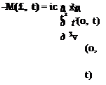
Recalling from the second of Eqs. (3.197) that Y + m2Y = 0, these relationships simplify to

Подпись:Подпись: (3.223)-[ EI(0) X//(0)]/ = – mc «2 X(0) EI(0) X "(0) = – ic о? X ‘(0) which, for a spanwise uniform beam, may be simplified to

mX //7(0) = mc a4 X(0) mX "(0) = – ic a4 X ‘(0)

Boundary Conditions Подпись: (3.224)

Eqs. (3.223) apply when a rigid body is attached to a free end. For a particle, we may simply set ic = 0. Finally, at the opposite end of the beam, we need only change the signs of the stress resultants, so that

(a) beam with positive stress resultants at x=l

Подпись: M{£ AПодпись: (b) rigid body with contact force and moment from beamBoundary ConditionsFigure 3.32. Example with rigid body attached to the right end of beam undergoing bending

from which we may express boundary conditions on Xfor a spanwise uniform beam, given by

Подпись: (3.225)mX"'(l) = — mc a4 X(£) mX"(f) = IC a4 X ‘(€)

It is appropriate to note that the use of the second of Eqs. (3.225) allows us to express Eqs. (3.197) as

V(f, t) = mca/v(0, t)

9 (3.:

M(f, t) = Ic«2 ^ (0, t)

д X

subject to the restriction that these conditions hold true only for free vibration.

Other Boundary Configurations. We now turn our attention to two more examples, which are only slightly more involved. First, we consider a beam with an attached rigid body of mass mc and moment inertia about C given by IC. The body has a mass center that is offset from the point of attachment (at x = f) by a distance e, as shown in Fig. 3.32. (This is unlike the previous case in which the body mass center C is located at x = f and thus has e = 0; see Fig. 3.31.) The body mass center C is assumed to be on the x axis so that transverse vibrations do not excite torsional vibrations and vice versa. The sum of all forces acting on the body is

Подпись: (3.227)(LF)y s-V(f-‘)

Boundary Conditions Подпись: (3.228)

Euler’s first law says that this should be equated to the mass times the acceleration of C. The acceleration of C in the y direction can be written as

Boundary Conditions Подпись: (3.229)

where the body’s angular acceleration about the z axis (normal to the plane of the paper) is

Подпись: — V(f, t) = mc Boundary Conditions Подпись: (3.230)

Thus, Euler’s first law for the body is

Figure 3.33. Example with mechanism attached to the left end of beam undergoing bending

The sum of the moments about C in the z direction

Подпись: (3.231)

Boundary Conditions
Подпись: beam

(l]Mc)z = – M(£, t) + eV(l, t)

d 3 v

d 12д X

Eqs. (3.230) and (3.232) can be combined to solve for V(l, t) and M(l, t), yielding

d3v „ d2v

d 3v

Boundary Conditions Подпись: (3.232)
Подпись: (3.233)
Подпись: M(l, t) ^ EI(l)dxz(£, t)
Подпись: V(l, t) ^ -
Подпись: д
Подпись: д X
Подпись: д 2 v EI(l) )
Подпись: (3.234)

Euler’s second law says that this should be equated to the moment of inertia about C times the angular acceleration about the z axis, so that

The last example involves a mechanism attached to the left end of a beam with a pinned connection to ground, as shown in Fig. 3.33. The massless rigid rod is of length h and the particle has mass mc; this combination should be considered a rigid body with mass mc and moment of inertia about the pivot mch2. The massless rod is embedded in the left end of the beam and rotates with it. A positive rotation of the x = 0 cross-sectional plane about the normal to the page (i. e., the z axis) is counterclockwise and has the value

dv

№ t) = T-(0, t) (3.235)

д X

This rotation results in the downward motion of the particle by the distance hp (0, t) and leads to the upward force exerted by the spring, khp(0, t). Thus, this body has a free-body diagram, as shown in Fig. 3.34. A rotation of the rigid body is positive in the counterclockwise direction. Denoting the pivot as O, we find that the sum of moments on the mechanism is

Подпись:(EMo)z = M(0, t) – kh2dv(0, t)

beam

Boundary ConditionsFigure 3.34. Free-body diagram for example with mechanism attached to the left end of beam undergoing bending

Here, Euler’s second law is applied about the pivot to avoid dealing with reaction forces at O. This requires us to equate the sum of the moments about O to the moment of inertia about O times the angular acceleration; viz.

Подпись: (3.237)Подпись: (3.238)dv d 3 v

M(°’ )- uh ix (°’ )="kl’2 wxx (°’ )

or

EI S<°’’ )- k’2 ё (0t ) = ”""2 ШХ (0t )

Boundary Conditions Подпись: (3.239)

The corresponding boundary condition on X at x = ° is found to be

As always with bending problems, one other boundary condition applies at x = ° for the configuration shown in Fig. 3.33—namely, v(°, t) = X(°) = °.

Equation of Motion

Подпись: д X2 Equation of Motion Подпись: d 2 V + m dt2 = f (X’ 1) Подпись: (3.194)

From Section 2.3.2, Eq. (2.53) is repeated here for convenience

In the following sections, we treat the special case of free vibration for which

f (x, t) = 0.

3.3.1 General Solutions

A solution to the equation of motion for the transverse vibrations of beams can be obtained by a separation of the independent variables. This separation is denoted as

v(x, t) = X(x)Y(t) (3.195)

which, when substituted into the equation of motion, yields

Подпись: (3.196)(EIX")" Y

mX = – Y

Because the dependencies on x and t were separated across the equality, each side must equal a constant—say, m2. The resulting ordinary differential equations then become

Подпись: (3.197)(EIX")" – mm2X = 0 Y + m2 Y = 0

For simplicity, we specialize the equations for the case of spanwise uniformity of all properties so that the first of Eqs. (3.197) simplifies to

Подпись: X"" = a4 X (3.198) 2 4 mm2 a = EI (3.199) where

is a constant.

For a = 0, the general solution to the second of Eqs. (3.197) can be written as in the cases for the string and beam torsion; namely

Y(t) = Asin(mt) + B cos(mt) (3.200)

For a = 0, the general solution to the spatially dependent equation can be obtained by presuming a solution of the form

Подпись: (3.201)X(x) = exp(Xx)

Substitution of this assumed form into the fourth-order differential equation for X(x) yields

X4 – a4 = 0 (3.202)

which can be factored to

(X — i a)(X + i a)(X — a)(X + a) = 0 (3.203)

indicating a general solution of the form

X(x) = C1 exp(iax) + C2 exp(—iax) + C3 exp(ax) + C4 exp(—ax) (3.204)

Rewriting the exponential functions as trigonometric and hyperbolic sine and cosine functions yields an alternative form of the general solution as

X(x) = D1 sin(ax) + D2 cos(ax) + D sinh(ax) + D4 cosh(ax) (3.205)

Eventual determination of the constants Di (i = 1, 2, 3, and 4) and a requires spec­ification of appropriate boundary conditions. To facilitate this procedure, this last solution form can be rearranged to provide, in some cases, a slight advantage in the algebra, so that

Подпись:X(x) = £1[sin(ax) + sinh(ax)] + E2[sin(ax) – sinh(ax)]

+ E3[cos(ax) + cosh(ax)] + E4[cos(ax) – cosh(ax)]

To complete the solution, the constants A and B can be determined from the initial deflection and rate of deflection of the beam. The remaining four constants, Ci, Di, or Ei (i = 1,2,3, and 4), can be evaluated from the boundary conditions, which must be imposed at each end of the beam. As was true for torsion, the important special case of a = 0 is connected with rigid-body modes for beam bending and is addressed in more detail in Section 3.3.4.