Category Introduction to Structural Dynamics and Aeroelasticity

Uniform String Dynamics

To more easily understand a mathematical description of the mechanics associated with the structural dynamics of continuous elastic systems, the classical “vibrating – string problem” is first considered. Although the free-vibration of a string can be described by the linear second-order partial differential equation in one dimen­sion derived in Chapter 2 (see Eq. 2.26), it is typically descriptive of the more complex linearly elastic systems of aerospace vehicles. After the fundamental con­cepts are reviewed for the string, other components that are more representative of these vehicles are discussed. Although the free vibration of a string can be ana­lyzed using equations of motion of the same form as those governing uniform beam extensional and torsional vibrations, the string is chosen as our first example pri­marily because—in contrast to the behavior of the other structures—string behavior can be visualized easily. Moreover, typically by this time in their undergraduate studies, most students have had some exposure to the solution of string-vibration problems.

Structural Dynamics

Подпись: 3O students, study mathematics, and do not build without foundations….

—Leonardo da Vinci

The purpose of this chapter is to convey to students a small introductory portion of the theory of structural dynamics. Much of the theory to which the students will be exposed in this treatment was developed by mathematicians during the time between Newton and Rayleigh. The grasp of this mathematical foundation is therefore a goal that is worthwhile in its own right. Moreover, as implied by the da Vinci quotation, a proper use of this foundation enables the advance of technology.

Structural dynamics is a broad subject, encompassing determination of natural frequencies and mode shapes (i. e., the so-called free-vibration problem), response due to initial conditions, forced response in the time domain, and frequency response. In the following discussion, we deal with all except the last category. For response problems, if the loading is at least in part of aerodynamic origin, then the response is said to be aeroelastic. In general, the aerodynamic loading then will depend on the structural deformation, and the deformation will depend on the aerodynamic load­ing. Linear aeroelastic problems are considered in subsequent chapters, and linear structured dynamics problems are considered in the present chapter. Other impor­tant phenomena, such as limit-cycle oscillations of lifting surfaces, must be treated with sophisticated nonlinear-analysis methodology; however, they are beyond the scope of this text.

The value of structural dynamics to the general study of aeroelastic phenomena is its ability to provide a means of quantitatively describing the deformation pattern at any instant in time for a continuous structural system in response to external loading. Although there are many methods of approximating the structural-deformation pattern, several of the widely used methods are reducible to what is called a “modal representation” as long as the underlying structural modeling is linear. The purpose of this chapter is to establish the concept of modal representation and show how it can be used to describe the dynamic behavior of continuous elastic systems. Also included is an introductory treatment of the Ritz and Galerkin methods, techniques that use assumed modes or similar sets of functions to obtain approximate solutions in
a simple way. Indeed, both methods are close relatives of the finite element method, a widely used approximate method that can accurately analyze realistic structural configurations. Only the basics of applying the finite element method to beams are covered herein; details of this method are in books that offer a more advanced perspective on structural analysis, several of which are listed in the references.

The analytical developments presented in this chapter are conceptually similar to the methods of analysis conducted on complete flight vehicles. In an effort to maintain analytical simplicity, the continuous structural configurations to be exam­ined are all uniform and one-dimensional. Although such structures may appear impractical relative to conventional aircraft, they exhibit structural dynamic prop­erties and representations that are essentially the same as those of full-scale flight vehicles.

Systems with One Degree of Freedom

The behavior of systems with one degree of freedom is of interest in its own right. Through the various forms of modal approximations, such as the Ritz and Galerkin methods (see Section 3.5), the behavior of complex systems frequently can be re­duced to a set of equations each having the form of a single-degree-of-freedom system. Therefore, it is worthwhile to explore the various types of behavior we associate with such systems.

Consider a particle of mass m, restrained by a spring with elastic constant к and a damper with damping constant c, and forced with a function f (t) (Fig. 2.10). The governing equation can be written

mx + cx + kx = f (t) (2.66)

where x(t) is the single unknown, typically a displacement or rotation but not limited to such. Here, the mass m, the damping c, and the stiffness к are the system parameters and f (t) is a forcing function. Our interest in this system is limited for now in two special cases: (1) unforced motion, with f (t) as identically zero; and (2) harmonically forced motion.

1.4.3 Unforced Motion

Eq. (2.66) for unforced motion is given by

mx + cx + kx = 0 (2.67)

к

Az(t)

Systems with One Degree of Freedom

Systems with One Degree of Freedom

Figure 2.10. Single-degree-of-freedom system

An exhaustive treatment of this equation is beyond the scope of this text. Suffice it to say that for our purposes, we are concerned with the qualitative aspects of the motion for various combinations of parameter values. We are interested in both positive and negative stiffness and damping. To facilitate exploration of the behavior, we define the natural frequency m such that к = mm2, divide the equation by m, and introduce the damping ratio Z so that c = 2mZm. Then, the equation of motion reduces to

x + 2Zmx + m2 x = 0 (2.68)

another advantageous step is to introduce dimensionless time f = mt, derivatives with respect to which are denoted by ()’. With this, Eq. (2.68) becomes

Подпись: (2.69)x" + 2Z x’ + x = 0

We are mostly concerned about the response of systems with small damping ratios, in which Z < 1. For this case, the general solution is

Подпись: (2.70)x(f) = e^Zf a cos ^/1 – Z2 f) + b sin ^/1 – Z2 f) x'(f) = e-Zf (by7 1 – Z2 – Za) cos ^/1 – Z2f)

– (Z b + aj 1 – Z2) sin ^1 – Z2 f)

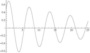
The responses caused by arbitrary initial displacement and velocity can be con­structed by combining the responses to unit initial displacement and unit initial velocity. For the first, we let x(0) = 1 and x'(0) = 0, which together imply that a = 1 and b = Zll 1 – Z2. For the second, we let x(0) = 0 and x'(0) = 1, which together imply a = 0 and b = 1Д/1 – Z2. In all cases, the displacement and velocity both exhibit an oscillatory character with a decaying amplitude for Z > 0 and a growing amplitude for Z < 0. Positive damping leads to a decaying response signal (Fig. 2.11) and negative damping to a growing response signal (Fig. 2.12).

a cosh (ty/1 + Z 2) + b sinh (t^/1 + Z 2)

Подпись: x(f) = e Zt Подпись: (2.71)

Actual mechanical systems always have positive stiffness. However, with the advent of active materials, it is possible to have a negative effective stiffness. Also, in the field of aeroelasticity, aerodynamics can contribute a negative stiffening effect that possibly overpowers the positive stiffness from the structure or the support. When a system has a negative effective stiffness, the response can be written as

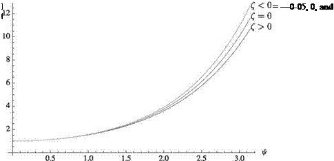
This function is only slightly affected by the sign of Z and the initial conditions. Typ­ical results are shown in Fig. 2.13. Response for negative stiffness is nonoscillatory divergent motion. Damping makes little difference when the stiffness is negative, although response is slightly larger for negative damping. In summary, when in­stabilities are encountered, the system response is divergent and may be either nonoscillatory or oscillatory.

Systems with One Degree of Freedom

Figure 2.11. Response for system with positive k and x(0) = x'(0) = 0.5, Z = 0.04 2.6.2 Harmonically Forced Motion

We now consider the case of harmonically forced motion, where f (t) is a harmonic function of the form f (t) = kAcos(Qt). The response to harmonically excited mo­tion is a subject worthy of study, but we hardly “scratch the surface” in this brief discussion. For the present purpose, we consider the equation of motion written as

mx + cx + kx = kAcos(Qt) (2.72)

Dividing through by m, we find

X + 2ZmX + a2 x = Am2 cos(Ut) = Aa? el at (2.73)

x(ф)

Systems with One Degree of Freedom

Figure 2.12. Response for system with positive k and x(0) = x'(0) = 0.5, Z = —0.04

with X as a complex variable and the actual displacement being found as the real part of x. Considering only the steady-state part of the response, we may assume

Подпись: (2.74)

Systems with One Degree of Freedom

x = Xe1 Ut

Подпись: A = G(i U) Подпись: 1 1 — (U )2 + 2i Z* Подпись: (2.75)

Substitution of Eq. (2.74) into Eq. (2.73) yields

where G(i U) is the frequency response. This form allows us to write the solution as

Подпись: (2.76)x = A| G(i U) | cos(Ut — ф)

Подпись: |G(i U)| Systems with One Degree of Freedom Подпись: (2.77)

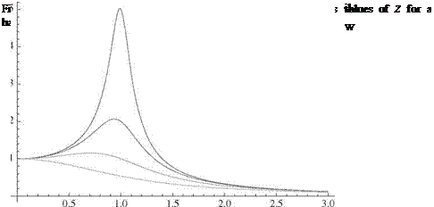
where | G(i U) | is known as the magnification factor, given by

Подпись: ф = tan 1 Подпись: 2ZU 1 — (U )2 Подпись: (2.78)

and plotted in Fig. 2.14. The phase angle

shows the delay between the peaks in f (t) at t = 2nn/U, and the peaks in x(t) at t = ф/U + 2nn/U for n = 0,1,

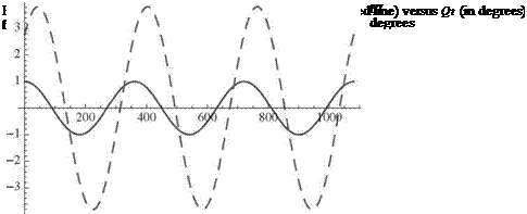
Now, as an example, we may consider a harmonic forcing function f (t) with A = 1 plotted along with x(t) for a particular choice Z and U/ш in Fig. 2.15. Here, the phase lag is noticeable as the response peaks are shifted approximately 43.45 degrees to the right.

Systems with One Degree of Freedom

am

Harmonically forced systems also may exhibit a large and possibly dangerous response in the case of resonance, where the driving frequency Q is very near a. For undamped systems, the response grows as

A

2 [t sin(at) + cos(at)] (2.79)

whereas the response amplitude reaches 1/(2z ) for lightly damped systems.

1.5 Epilogue

Systems with One Degree of Freedom

In this chapter, we laid out the foundational theories of mechanics that are needed for an introductory treatment of structural dynamics and aeroelasticity. It is hoped

that students find it helpful to be able to refer to these treatments as they are applied throughout the remainder of the text. Structural dynamics and aeroelasticity analyses of realistic aircraft structural elements may require more sophisticated theories, such as plate and shell theory and full three-dimensional finite-element analysis; however, such treatments are beyond the scope of this text.

The Notion of Stability

Consider a structure undergoing external loads applied quasistatically. In such a case, static equilibrium is maintained as the elastic structure deforms. If now at any level of the external force a “small” external disturbance is applied, and the structure reacts by simply performing oscillations about the deformed equilibrium state, the equilibrium state is said to be stable. This disturbance can be in the form of deformation or velocity; by “small,” we mean “as small as desired.” As a result of this latter definition, it is more appropriate to say that the equilibrium is stable for a small disturbance. In addition, we stipulate that when the disturbance is introduced, the level of the external forces is kept constant. Conversely, if the elastic structure either (a) tends to and remains in the disturbed position, or (b) diverges from the equilibrium state, the equilibrium is said to be unstable. Some authors prefer to distinguish these two conditions and call the equilibrium “neutrally stable” for case (a) and “unstable” for case (b). When either of these two cases occurs, the level of the external forces is referred to as “critical.”

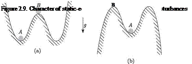
This is illustrated using the system shown in Fig. 2.8. This system consists of a ball of weight W resting at different points on a surface with zero curvature normal to the plane of the figure. Points of zero slope on the surface denote positions of static equilibrium (i. e., points A, B, and C). Furthermore, the character of equilibrium at these points is substantially different. At A, if the system is disturbed through infinitesimal disturbances (i. e., small displacements or small velocities), it simply oscillates, about the static-equilibrium position A. Such an equilibrium position is called stable for small disturbances. At point B, if the system is disturbed, it tends to move away from the static-equilibrium position B. Such an equilibrium position is called unstable for small disturbances. Finally, at point C, if the system is disturbed, it tends to remain in the disturbed position. Such an equilibrium position is called neutrally stable or indifferent for small disturbances. The expression “for small disturbances” is used because the definition depends on the small size of the perturbations and is the foundational reason we may use linearized equations to conduct the analysis. If the disturbances are allowed to be of finite magnitude, then it is possible for a system to be unstable for small disturbances but stable for large disturbances (i. e., point B, Fig. 2.9a) or stable for small disturbances but unstable for large disturbances (i. e., point A, Fig. 2.9b).[2]

Constitutive Law and Strain Energy for Coupled Bending and Torsion

A straightforward way to introduce such coupling in the elementary beam equations presented previously is to alter the “constitutive law” (i. e., the relationship between cross-sectional stress resultants and the generalized strains). So, we change

where EI is the effective bending stiffness, GJ is the effective torsional stiffness, and K is the effective bending-torsion coupling stiffness (with the same dimensions as EI and GJ). Whereas EI and GJ are strictly positive, K may be positive, negative, or zero. A positive value of K implies that when the beam is loaded with an upward vertical force at the tip, the resulting positive bending moment induces a positive (i. e., nose-up) twisting moment. Values of GJ, EI, and K are best found by cross-sectional codes such as VABS™ a commercially available computer program developed at Georgia Tech (Hodges, 2006).

Подпись: where the 2 x 2 matrix must be positive-definite for physical reasons. This means that of necessity, K2 < EI GJ.

Now, given Eq. (2.58), it is straightforward to write the strain energy as

1.4.1 Inertia Forces and Kinetic Energy for Coupled Bending and Torsion

Constitutive Law and Strain Energy for Coupled Bending and Torsion Подпись: (2.60)

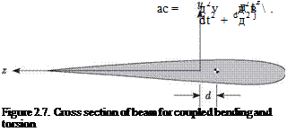
In general, there is also inertial coupling between bending and torsional deflections. This type of coupling stems from d, the offset of the cross-sectional mass centroid from the x axis shown in Fig. 2.7 and given by

Constitutive Law and Strain Energy for Coupled Bending and Torsion Подпись: (2.61)

so that the acceleration of the mass centroid is

For inhomogeneous beams, the offset d may be defined as the distance from the x axis to the cross-sectional mass centroid, positive when the mass centroid is toward the leading edge from the x axis.

Подпись: Hc = Constitutive Law and Strain Energy for Coupled Bending and Torsion Подпись: (2.62)

Similarly, if one neglects rotary inertia of the cross-sectional plane about the z axis, the angular momentum of the cross section about c is

where, for beams in which the material density varies over the cross section, we may calculate the cross-sectional mass polar moment of inertia as

PIP = U p (y2 + z2) dA (2.63)

A

Constitutive Law and Strain Energy for Coupled Bending and Torsion Constitutive Law and Strain Energy for Coupled Bending and Torsion Подпись: dx Подпись: (2.64)
Constitutive Law and Strain Energy for Coupled Bending and Torsion

The kinetic energy follows from similar considerations and can be written di­rectly as

1.4.2 Equations of Motion for Coupled Bending and Torsion

Подпись: Using the coupled constitutive law and inertia forces, the partial differential equations of motion for coupled bending and torsion of a composite beam become д2в д2v д ( дв д2v  p 11 дА + md W - дХ GJ дХ - K SA =r (x ‘) (2.65) д 2v д2в д2 д 2v дв

m дР + dдР + АР EIАР – K А* = f (x”)

where we see the structural coupling through K and the inertial coupling through d.

Of course, we may simplify these equations for isotropic beams undergoing coupled bending and torsion simply by setting K = 0.

Figure 2.8. Character of static-equili­brium positions

Composite Beams

Recall that the x axis (i. e., the axial coordinate) for homogeneous, isotropic beams is generally chosen as the locus of cross-sectional shear centers. This choice is fre­quently denoted as the “elastic axis” because it structurally uncouples torsion from both transverse shearing deformation and bending. Thus, transverse forces acting through this axis do not twist the beam. However, even for spanwise uniform com­posite beams, when transverse shear forces act through any axis defined as the locus of a cross-sectional property, it is still possible that these forces will twist the beam
because bending-twist coupling may be present. For the type of composite-beam analysis presented herein, we still choose the x axis to be along the locus of shear centers; but, for composite beams, this choice uncouples only torsion and transverse shear deformation. Therefore, although transverse shear forces acting through the x axis do not directly induces twist, the bending moment induced by the shear force still induces twist when bending-twist coupling is present.

Bending

As in the case of torsion, the beam is initially treated as having nonuniform properties along the x axis. The x axis is taken as the line of the individual cross-sectional neutral axes associated with pure bending in and normal to the plane of the diagram in Fig. 2.5. For simplicity, however, we consider only uncoupled bending in the x-y plane, thus excluding initially twisted beams from the development. The bending deflections are denoted by v(x, t) in the y direction. The x axis is presumed to be straight, thus excluding initially curved beams. We continue to assume for now that the properties of the beam allow the x axis to be chosen so that bending and torsion are both structurally and inertially uncoupled. Therefore, in the plane(s) in which bending is taking place, the loci of both shear centers and mass centers must also coincide with the x axis. Finally, the transverse beam displacement, v, is presumed small to permit a linearly elastic representation of the deformation.

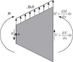
Equation of Motion. A free-body diagram for the differential-beam segment shown in Fig. 2.6 includes the shear force, V, and the bending moment, M. Recall from our previous discussion on torsion that an outward-directed normal on the positive x face is directed to the right, and an outward-directed normal is directed to the left on the negative x face. By this convention, V is the resultant of the transverse shear stresses

Bending

Bending

Figure 2.6. Schematic of differential beam segment

in the positive y direction (upward in Fig. 2.6) on a positive x cross-sectional face and in the negative y direction on a negative x cross-sectional face. In other words, a positive shear force tends to displace the positive x face upward and the negative x face downward, as depicted in Fig. 2.6. The bending moment, M, is the moment of the longitudinal stresses about a line parallel to the z axis (perpendicular to the plane of the diagram in Fig. 2.6) at the intersection between the cross-sectional plane and the neutral surface. Thus, a positive bending moment tends to rotate the positive x face positively about the z axis (in the right-handed sense) and the negative x face negatively about the z axis. This affects the boundary conditions, which are examined in detail in connection with applications of the theory in Chapter 3. The distributed loading (with units of force per unit length) is denoted by f (x, t). The equation of motion for transverse-beam displacements can be obtained by setting the resultant force on the segment equal to the mass times the acceleration, which yields

/ д V d2v

f (x, t)dx — V + I V +- dx I = mdx—2 (2.47)

V д x / д t2

and leads to

д V д 2 v

– + f(x.,) = m -2: (2-48)

Подпись: —M + Подпись: д M M + dx д x Подпись: + Подпись: д V V + dx д x Подпись: dx + Bending Подпись: (2.49)

where m is the mass per unit length, given by p A for homogeneous cross sections. We must also consider the moment equation. We note here that the cross-sectional rotational inertia about the z axis will be ignored because it has a small effect. Taking a counterclockwise moment as positive, we sum the moments about the point a to obtain

which, after we neglect the higher-order differentials (i. e., higher powers of dx), becomes

+ V = 0 (2.50)

д x

Recall that the bending moment is proportional to the local curvature; therefore

__ д 2v

M = EI w (2-51)

Bending Подпись: (2.52)

where EI may be regarded as the effective bending stiffness of the beam at a particular cross section and hence may vary with x. Note that for isotropic beams, calculation of the bending rigidity is a straightforward integration over the cross section, given by

where E is the Young’s modulus. When the beam is homogeneous the Young’s modulus may be moved outside the integration so that EI = EI where I is the cross­sectional area moment of inertia about the z axis for a particular cross section. Here, the origin of the y and z axes is at the sectional centroid. However, when one or more of the constituent materials is anisotropic, determination of the effective bending rigidity becomes more difficult to perform rigorously. For additional discussion of this point, see Section 2.4.

Подпись: д X2 Bending Подпись: d 2V + m df = f (X,1) Подпись: (2.53)

Substitution of Eq. (2.51) into Eq. (2.50) and of the resulting equation into Eq. (2.48) yields the partial differential equation of motion for a spanwise nonuni­form beam as

Strain Energy. The strain energy of an isotropic beam undergoing pure bending deformation can be written as

Bending(2.54)

This is also an appropriate expression for the bending strain energy for a composite beam without elastic coupling.

Kinetic Energy. The kinetic energy of a beam undergoing bending deformation can be written as

Подпись: K =Подпись: 1Подпись: 2Bending(2.55)

just as for a vibrating string. For a spanwise nonuniform beam, m may vary with X.

Virtual Work of Applied, Distributed Force. The virtual work of an applied dis­tributed force f (x, t) on a beam undergoing bending deformation may be computed as

S W = f f(x, t)8v(x, t)dx (2.56)

J0

just as for a vibrating string.

Elementary Beam Theory

Now that we have considered the fundamental aspects of structural dynamics analysis for strings, these same concepts are applied to the dynamics of beam torsional and bending deformation. The beam has many more of the characteristics of typical aeronautical structures. Indeed, high-aspect-ratio wings and helicopter rotor blades are frequently idealized as beams, especially in conceptual and preliminary design. Even for low-aspect-ratio wings, although a plate model may be more realistic, the bending and torsional deformation can be approximated by use of beam theory with adjusted stiffness coefficients.

2.3.1 Torsion

In an effort to retain a level of simplicity that promotes tractability, the St. Venant theory of torsion is used and the problem is idealized to the extent that torsion is uncoupled from transverse deflections. The torsional rigidity, denoted by GJ, is taken as given and may vary with x. For homogeneous and isotropic beams, GJ = GJ, where G denotes the shear modulus and J is a constant that depends only on the geometry of the cross section. To be uncoupled from bending and other types of deformation, the x axis must be along the elastic axis and also must coincide with the locus of cross-sectional mass centroids. For isotropic beams, the elastic axis is along the locus of cross-sectional shear centers.

For such beams, J can be determined by solving a boundary-value problem over the cross section, which requires finding the cross-sectional warping caused by

torsion. Although analytical solutions for this problem are available for simple cross­sectional geometries, solving for the cross-sectional warping and torsional stiffness is, in general, not a trivial exercise and possibly requires a numerical solution of Laplace’s equation over the cross section. Moreover, when the beam is inhomo­geneous with more than one constituent material and/or when one or more of the constituent materials is anisotropic, we must solve a more involved boundary-value problem over the cross-sectional area. For additional discussion of this point, see Section 2.4.

Equation of Motion. The beam is considered initially to have nonuniform properties along the x axis and to be loaded with a known, distributed twisting moment r(x, t). The elastic twisting deflection, в, is positive in a right-handed sense about this axis, as illustrated in Fig. 2.3. In contrast, the twisting moment, denoted by T, is the structural torque (i. e., the resultant moment of the tractions on a cross-sectional face about the elastic axis). Recall that an outward-directed normal on the positive x face is directed to the right, whereas an outward-directed normal on the negative x face is directed to the left. Thus, a positive torque tends to rotate the positive x face in a direction that is positive along the x axis in the right-hand sense and the negative x face in a direction that is positive along the – x axis in the right-hand sense, as depicted in Fig. 2.3. This affects the boundary conditions, which are discussed in connection with applications of the theory in Chapter 3.

Letting p Ipdx be the polar mass moment of inertia about the x axis of the differential beam segment in Fig. 2.4, we can obtain the equation of motion by equating the resultant twisting moment on both segment faces to the rate of change of the segment’s angular momentum about the elastic axis. This yields

d T d 2 в

T + – dx – T + r(x, t)dx = pIpdx —2 (2.39)

d x d t2

Подпись: «■ T Elementary Beam Theory

Elementary Beam Theory

Figure 2.4. Cross-sectional slice of beam undergoing torsional deformation

or

d T __

– + r (x.<) = p I, ^ (2.40)

where the polar mass moment of inertia is

p Ip = jJ p (y2 + z2) dA (2.41)

A

Here, A is the cross section of the beam, y and z are cross-sectional Cartesian coordinates, and p is the mass density of the beam. When p is constant over the cross section, then p I, = p Ip, where I, is the polar area moment of inertia per unit length. In general, however, p I, may vary along the x axis.

The twisting moment can be written in terms of the twist rate and the St. Venant torsional rigidity GJ as

Подпись: (2.42)T = GJ —

д X

-д 2в

Подпись: д д X Elementary Beam Theory Подпись: (2.43)

Substituting these expressions into Eq. (2.40), we obtain the partial-differential equation of motion for the nonuniform beam given by

Strain Energy. The strain energy of an isotropic beam undergoing pure torsional deformation can be written as

1 7 ^ / дв 2

U = 2 I GJ{~x)dx (2.44)

This is also an appropriate expression of torsional strain energy for a composite beam without elastic coupling.

Подпись: p Ip Подпись: (2.45)

Kinetic Energy. The kinetic energy of a beam undergoing pure torsional deforma­tion can be written as

Virtual Work of Applied, Distributed Torque. The virtual work of an applied dis­tributed twisting moment r (x, t) on a beam undergoing torsional deformation may be computed as

S W = f r (x, t)SO (x, t)dx (2.46)

J0

where SO is the variation of O (x, t), the angle of rotation caused by twist. Note that SO may be thought of as an increment of O (x, t) that satisfies all geometric constraints.

Kinetic Energy

Подпись: dK = m 2 Подпись: д u2 ( dvx2’ д) + І д Подпись: dx Подпись: (2.36)

To solve problems involving the forced response of strings using Lagrange’s equa­tion, we also need the kinetic energy. The kinetic energy for a differential length of string is

Recalling that the longitudinal displacement u was shown previously to be less significant than the transverse displacement v and to uncouple from it for small – perturbation motions about the static-equilibrium state, we may now express the

Kinetic Energy Подпись: (2.37)

kinetic energy of the whole string over length I as

2.2.2 Virtual Work of Applied, Distributed Force

To solve problems involving the forced response of strings using Lagrange’s equa­tion, we also need a general expression for the virtual work of all forces not accounted for in the potential energy. These applied forces and moments are identified most commonly as externally applied loads, which may or may not be a function of the response. They also include any dissipative loads, such as those from dampers. To determine the contribution of distributed transverse loads, denoted by f (x, t), the virtual work may be computed as the work done by applied forces through a virtual displacement, viz.

Kinetic Energy(2.38)

where the virtual displacement Sv also may be thought of as the Lagrangean variation of the displacement field. Such a variation may be thought of as an increment of the displacement field that satisfies all geometric constraints.

Equations of Motion

Equations of Motion
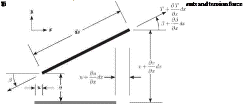
A string of initial length £0 is stretched in the x direction between two walls separated by a distance I > £0. The string tension, T(x, t), is considered high, and the transverse displacement v(x, t) and slope в(х, t) are eventually regarded as small. At any given instant, this system can be illustrated as in Fig. 2.1. To describe the dynamic behavior of this system, the forces acting on a differential length dx of the string can be illustrated by Fig. 2.2. Note that the longitudinal displacement u(x, t), transverse displacement, slope, and tension at the right end of the differential element are

represented as a Taylor series expansion of the values at the left end. Because the string segment is of a differential length that can be arbitrarily small, the series is truncated by neglecting terms of the order of dx2 and higher.

д ‘Г (аЛ d2u – [TcosOT] = m—г

Подпись: д d2v - ITrntf)] = m Подпись: (2.15)

Neglecting gravity and any other applied loads, two equations of motion can be formed by resolving the tension forces in the x and y directions and setting the resultant force on the differential element equal to its mass mdx times the acceleration of its mass center. Neglecting higher-order differentials, we obtain the equations of motion as

Equations of Motion Подпись: (2.16)

where for a string homogeneous over its cross section

is the mass per unit length. From Fig. 2.2, ignoring second and higher powers of dx and letting ds = (1 + e)dx where e is the elongation, we can identify

Подпись: rb 0+ д u д x 1 дv 1 + e д x Подпись: cos(e ) sin(e)(2.17)

Equations of Motion Equations of Motion Подпись: 2 + Подпись: дv д x Подпись: 2 1 Подпись: (2.18)

Noting that cos2(e) + sin2(e) = 1, we can find the elongation e as

Finally, considering the string as homogeneous, isotropic, and linearly elastic, we can write the tension force as a linear function of the elongation, so that

T = EAe (2.19)

where EA is the constant longitudinal stiffness of the string. This completes the system of nonlinear equations that govern the vibration of the string. To develop analytical solutions, we must simplify these equations.

Let us presuppose the existence of a static-equilibrium solution of the string deflection so that

u(x, t) = u(x) v(x, t) = 0

в (x, t) = 0 (2.20)

e(x, t) = e(x)

T(x, t) = T(x)

We then find that such a solution exists and that if u(0) = 0

T(x) = To

ч T0 5 n 014

e (x) = "0 = EA = £ <2-21)

u(x) = e0x

where TO and e0 are constants and 5 = £ – £0 is the change in the length of the string between its stretched and unstretched states.

If the steady-state tension T0 is sufficiently high, the perturbation deflections about the static-equilibrium solution are very small. Thus, we can assume

u(x, t) = u(x) + U(x, t) v(x, t) = V(x, t)

e(x, t) = e(x, t) (2.22)

e(x, t) = e(x) + e(x, t)

T(x, t) = T(x) + T(x, t)

where the () quantities are taken to be infinitesimally small. Furthermore, from the second of Eqs. (2.17), we can determine в in terms of the other quantities; that is

Подпись:1 dv 1 + e0 d x

Substituting the perturbation expressions of Eqs. (2.22) and (2.23) into Eqs. (2.15) while ignoring all squares and products of the () quantities, we find that the equations of motion can be reduced to two linear partial differential equations

„ .92U d2U

EA—- = m—г

Подпись:9×2 dt2

T0 d2v d2v

1 + Є0 dx2 m d t2

Thus, the two nonlinear equations of motion in Eqs. (2.15) for the free vibration of a string have been reduced to two uncoupled linear equations: one for longitudinal vibration and the other for transverse vibrations. Because it is typically true that EA > T0, longitudinal motions have much smaller amplitudes and much higher natural frequencies; thus, they are not usually of interest. Moreover, the fact that EA > T0 leads to the observations that e0 < 1 and 5 < £0 (see Eqs. 2.21). Thus, the transverse motion is governed by

d 2v d 2v 70 dx2 = m 9f2

For convenience, we drop the ()s and the subscript, thereby yielding the usual equation for string vibration found in texts on vibration

Подпись: (2.26)d 2v d 2 v

T—r = m—T – dx2 dt2

This is called the one-dimensional “wave equation,” and it governs the structural dynamic behavior of the string in conjunction with boundary conditions and initial conditions. The fact that the equation is of second order both temporally and spatially indicates that two boundary conditions and two initial conditions need to be specified. The boundary conditions at the ends of the string correspond to zero displacement, as described by

Подпись: (2.27)v(0, t) = v(t, t) = 0

where it is noted that the distinction between t0 and t is no longer relevant. The general solution to the wave equation with these homogeneous boundary conditions comprises a simple eigenvalue problem; the solution, along with a treatment of the initial conditions, is in Section 3.1.

2.2.1 Strain Energy

To solve problems involving the forced response of strings using Lagrange’s equa­tion, we need an expression for the strain energy, which is caused by extension of the string, viz.

1 (t0 9

P =- EAe2dx (2.28)

2 Jo

Equations of Motion Подпись: . д u 1 + dx Подпись: 2 + Подпись: dv д X Подпись: 2 1 Подпись: (2.29)

where, as before

and the original length is t0. To pick up all of the linear terms in Lagrange’s equa­tions, we must include all terms in the energy up through the second power of the unknowns. Taking the pertinent unknowns to be perturbations relative to the stretched but undeflected string, we can again write

€ (X, t) = Є(x) + € (X, t)

u(x, t) = u(x) + U(x, t) (2.30)

v(x, t) = v(x, t)

For EA equal to a constant, the strain energy is

EA C t0

P = (є2 + 2€€ + €2) dx (2.31)

20

From Eqs. (2.21), we know that T = T0 and є = €0, where T0 and €0 are constants. Thus, the first term of P is a constant and can be ignored. Because T0 = ЕАє0, the

Подпись: P = Equations of Motion Подпись: e2 dx Подпись: (2.32)

strain energy simplifies to

Using Eqs. (2.29) and (2.30), we find that the longitudinal strain becomes

Подпись: (2.33)л _ dU 1 fdv2

Є дX + 2(1 + e0) V dx) +

where the ellipsis refers to terms of third and higher degree in the spatial partial derivatives of u and v. Then, when we drop all terms that are of third and higher degree in the spatial partial derivatives of U and 0, the strain energy becomes

Подпись:P=To Г £dx+2(тЬ f (ё)dx+^rj’* (ё

Assuming U (0) = її (£0) = 0, we find that the first term vanishes. Because perturba­tions of the transverse deflections are the unknowns in which we are most interested, and because perturbations of the longitudinal displacements are uncoupled from these and involve oscillations with much higher frequency, we do not need the last term. This leaves only the second term. As before, noting that e0 < 1 and dropping the о and subscripts for convenience, we obtain the potential energy for a vibrating string

Подпись: P=TEquations of Motion(2.35)

as found in vibration texts.

In any continuous system—whether a string, beam, plate, or shell—we may ac­count for an attached spring by regarding it as an external force and thus determining its contribution to the generalized forces. Such attached springs may be either dis­crete (i. e., at a point) or distributed. Conversely, we may treat them as added parts of the system by including their potential energies (see Problem 5). Be careful to not count forces twice; the same is true for any other entity as well.