Our heavyweight helicopter equal in the world does not have
In Rostov started production of the most load-lifting rotary-wing car The Russian holding «Helicopt[...]

Everything about aircrafts and helicopters. News and events in aviation worldwide. Civil, transportation, military helicopters and airplanes.

Everything about aircrafts and helicopters. News and events in aviation worldwide. Civil, transportation, military helicopters and airplanes.

Everything about aircrafts and helicopters. News and events in aviation worldwide. Civil, transportation, military helicopters and airplanes.

Everything about aircrafts and helicopters. News and events in aviation worldwide. Civil, transportation, military helicopters and airplanes.


The efficiency of a wing is influenced greatly by its aerofoil section or profile, which has some degree and type of camber and some thickness form (Fig. 2. Id). Fuselages and other similar-shaped components of a model also produce some lift force, depending again on their shape and angle of attack. Re-entry vehicles for space flight have been designed as ‘lifting bodies’ without wings, but for almost all practical purposes in aeromodelling, the lift contribution of fuselages may be ignored. However, a fuselage does produce forces analogous to lift which affect the stability of the model, almost invariably in ways that oppose the efforts of the stabiliser to hold the mainplane at a fixed angle of attack. Similar lateral unstabilising forces are resisted by fins, which are small wings set at right angles to the mainplane, producing sideways ‘lift’ to correct yaw and sideslipping.
For convenience, aerodynamicists adopt a convention which allows all the very complex factors of wing trim and shape to be summed up in one figure, the coefficient of lift. This tells how the model as a whole, or any part of it taken separately, is working as a lift producer. A lift coefficient or Cl of 1 -3 indicates more lifting effect than Cl = 1.0 or 0.6, while Cl — 0.0 indicates no lifting effect at all. Cl has no dimensions since it is an abstract figure for comparison purposes and calculations.
For level flight, the total lift force generated by a model must equal the total weight, so it is possible to write:
Total Lift = Total Weight, or L = W (Action = Reaction).
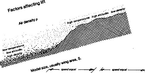
This will not apply exactly if the model is descending or climbing. The exact relationships between lift and weight for these conditions are given in Fig. 1.4. As Figure 2.1. shows, the factors affecting lift force are model size or area, speed of flight, air mass density and the aerofoil-plus-trim factor, Cl – In every case, an increase in one of these factors, greater
Fig 2.1 Contd.
 |
0 Lifting effect or lift coefficient CL
area, more speed, increased density or higher lift coefficient, will produce a larger lift force. It is to be expected that when a formula for lift is worked out, it will include all these factors. In mathematical language,
Lift = some function of p, V, S, and Cl
The standard, formula, which arises out of the basic principles of mechanics and the pioneer work of Daniel Bernoulli in the eighteenth century, is
L=HxpxV2xSxCL
It is not particulary important for modellers to know this formula but it is necessary to see how the various factors iii the lift equation are interdependent For a model to be capable of level flight the lift must equal the weight If the model’s weight increases (as when it turns out heavier than expected), a larger lift force will be needed to support it Some item on the right hand side of the equation, or more than one of them, must be increased. The
modeller has no control of air density, p. The model could be re-trimmed, increasing the wing’s angle of attack to get a higher Cl – More wing area might be added, although this would add mass and increase the speed of flight. Since V is squared in the formula (multiplied by itself), a relatively small increase in V yields a large increase in lift force, other things being equal. It follows from this that a heavy model (of given area, trim, etc.) has to fly faster than a light one. However, to increase V takes energy and in an extreme case the engine of the model may be incapable of giving sufficient power to sustain flight. In such a case, if launched from a height the model would descend at some angle like a glider, even with engine at full power.
However large and fast a model may be, its ability to gain lift will depend almost entirely on the form of the wing and its angle of attack relative to the airflow. The angle of attack is measured in degrees from some more or less arbitrary reference line, usually the straight line through the extreme leading and trailing edges of the wing aerofoil section or profile. In some cases, especially for an aerofoil with a flat underside, such as the Clark Y, a line tangential to the undersurface may be used. The angle between the reference line and the airflow at a distance from the wing is the geometric angle of attack. The aerodynamic angle of attack, i. e., the angle at which the air actually meets the wing, is almost always different from this, as will be explained in later pages.
The angle of attack (both geometric and aerodynamic) of the main wing is governed in orthodox models by the relative setting of wing and tailplane. The tailplane is a small wing which may or may not contribute lift to the total, but whose main function is to trim the mainplane to the desired angle of attack and hold it there. The angle of incidence of tail and wing to the fuselage must be distinguished from the angle of attack to the air. The fuselage itself may not be aligned with the airflow. (In this book, the term angle of attack is reserved for the angle of wing or tail airflow, and angle of incidence refers only to the rigging angle of such surfaces relative to some datum line on the drawing board. This convention is not always observed in other works on aerodynamics.)
Tails are sometimes arranged in V form, or even inverted V, when the longitudinal pitching and lateral stabilising and trimming functions are combined in the two surfaces of the V. Many other layouts than the orthodox wing-tailplane-fin style are possible, including tailless, tandem, delta and tail-first or canard aircraft All these and more can be made to fly and sometimes for special purposes may be superior to the standard arrangement.
Strictly, almost all ordinary aeroplanes and gliders are ‘tandems’ in that they have two wing-like surfaces disposed one behind the other and set at different rigging angles relative to one another. The relative areas and spans of these surfaces are matters of the designer’s choice. Whether one wing or the other carries most of the load or all of it is a matter of trim and centre of gravity position. If one of the pair of wings carries no load or very little, it functions only as a stabiliser and control surface and may then be very small relative to the main load-carrying wing.
In certain circumstances, the so-called ‘canard’ layout with a small, load-carrying wing ahead of a larger mainplane has certain advantages over the more usual mainplane/ tailplane arrangement. The first successful aeroplane, the Wright Brothers’ Flier of 1903, was a canard.
The reason why most aircraft have tailplanes rather than foreplanes will appear in more detail in Chapters 12 and 13. Although unorthodox aircraft sometimes appear to offer great advantages, the tailless type because it saves the drag and weight of fuselage and stabiliser, for instance, there are always certain disadvantages too, either in terms of excess drag from other causes, structural complexity, or, more often, problems of control and stability.
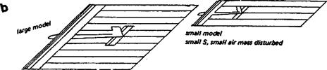
A large model, flying through air of standard density, must create more disturbance and hence generates more air reaction, both lift and drag, than a small model, at similar speed. The wing span in relation to the model weight, or span loading, is of some importance. A large span wing at a given speed sweeps through a larger mass of air than a short wing. To gain the same reactive forces, with a larger total mass to work on, smaller accelerations are needed. Span loading is expressed as a ratio, weight-per-unit-length (Newtons per metre, or pounds per foot). The capital letter W stands for weight, and the small letter b Sir span (breadth). Span loading = W/b.
Model size is more conveniently expressed in terms of wing area. Units such as square metres or square feet are employed, though these are rather large for modelling purposes and the F. A.I. Sporting Code quotes areas in square decimetres. (One square decimetre equals l/100th. sq. metre.) In this book areas will be given in square metres to conform to standard aerodynamic conventions. The capital letter S is used to stand for square measure, i. e., area.
2.2 VELOCITY
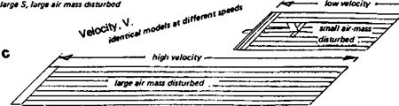
With a model of given span and area, a larger mass of air will be disturbed if speed is high than if low. Velocity, V, is expressed in metres or feet per second, rather than kilometres or miles per hour, in standard formulae (Fig. 2.1c).
Air is a mixture of gases, mostly nitrogen and oxygen. At the fundamental level, gases are regarded as consisting of enormous numbers of separate particles, called molecules, which are in violently agitated motion. The temperature of a gas is the measure of this molecular motion; low temperatures are states of less molecular motion than high temperatures. It is the impact of the moving particles which creates gas pressure on objects immersed in gas. Density is the measure of the number of molecules in a given space.
In low speed aerodynamics it is not necessary to consider the molecular structure of die air. The medium in which models fly is a fluid. This is not to say that air is a liquid. Liquids are fluids which are almost totally incompressible, gases are compressible fluids. Model aircraft do not (as yet) fly at such speeds that the compressibility of the air needs to be allowed for. This is true also for full-sized sailplanes and hang gliders, ultra light, light * and commercial aircraft up to medium sized piston-engined transport aeroplanes.
Compressibility problems do arise for jet-driven aeroplanes and for the tips of «propellers and helicopter rotors. For modelling purposes, fortunately, the air may always be regarded as an incompressible fluid. Even so, significant variations of density occur. *■ They are related to altitude and weather. In Appendix 1, charts (prepared by Jaroslav V, Lnenicka) indicate the magnitude of these effects. At high altitudes and in hot weather, i the air is less dense than near sea level when cold. Modellers operating on the high. plateaux of East Africa or the Americas find air density does make a difference since to
|
|
|
|
|
|
achieve the same air mass reactions to gain lift, their models have to fly faster. Engines and propellers are also adversely affected.
Density is usually expressed in kilogrammes per cubic metre (i. e. mass per unit volume), or in Imperial measure, slugs per cubic foot In aerodynamics a standard value for density of 1.225 kg/m3 (.002378 slugs/ft3) is assumed, corresponding to a sea level value at normal temperature and pressure. For most purposes in design this figure is • adequate. In formulae, the Greek letter p (rho) is used to stand for density (Fig. 2.1a).
2.1 ACTION AND REACTION FROM AIR
The air forces which act upon a model, both those which support it and those which resist its movement, arise from die properties of the air, which has mass. To generate supporting force a mass of air must be accelerated or deflected to yield an upward reaction which, for equilibrium, equals the weight. To work on the air the wing or wings of the model must move through it, disturbing it In addition to the wing, all other components of a model, such as fuselage, tailplane, undercarriage, etc., also disturb the air and add to the total of energy needed, without, in general, adding any lift. The greater the expenditure of energy required to generate a given lift force, the less the efficiency of the model.
The mass of air available for a model to work on depends on three factors: 1) the amount of air in a given space, i. e. the mass density of air where the model operates; 2) the size of the model; and 3) the speed or velocity of its flight (Fig. 2.1 a, b and c).
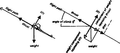
Gliding, either with engine throttled back or with no engine at all, is best understood if the forces are resolved as shown in Figure 1.4b. The weight alone acts vertically downwards, but may be resolved into one force acting along the flight path and another at right angles to it The glider, or gliding power model, moves forward and slightly downwards under the action of the weight component along the flight direction. The total air reaction force is similarly resolved into lift at right angles to the flight and drag opposing the forward-acting force. The result is a diagram very similar to that for powered flight but it has been rotated through a small angle, known as the glide angle. A steeper glide would cause a larger weight component to pull the model along its flight path. It would accelerate until the drag component of the air reaction once again grew large enough to restore equilibrium.
1.4 DIVING
In a dive, the four force diagram has rotated further, as shown in Figure 1.4d, and in the limiting case the flight path is vertically downwards, weight and thrust (if any) both pull the model down, the only opposing force is drag. The speed at which drag becomes large enough to equal weight-plus-thrust is usually very high and probably before this ‘terminal velocity’ is reached, the model would hit the ground (Fig. 1.4.f).
1.5 CLIMBING
In a climb, the total support comes from a combination of wings and propeller. The weight may be resolved into two components, one opposing lift and the other directly opposing thrust, assisting the drag. Again, the result is a four force arrangement in balance, but rotated through the angle of climb (Fig. 1.4.c). The limiting case is the vertical climb, when the weight plus drag is opposed only by the propeller. Such flight is commonplace to the helicopter, but a model of orthodox type, if sufficiently powered, is capable of vertical climbing in this fashion also. As the diagram shows, in such a climb the wing lift force must be zero, and its angle of the attack to the air flowing over it must be such as to give no lift It is therefore obvious that to obtain a steep climb there must be sufficient thrust from the motor since this, rather than the wing, provides the necessary reaction to equal the weight and drag resistance.
1.6 HOVERING
For a helicopter to hover, the thrust from the rotor must equal the weight plus a relatively small addition to compensate for the drag of the rotor’s slipstream over the body of tire aircraft. In a helicopter ascent some additional rotor thrust is needed because the air drag of the hull in the rotor wake increases. Ordinary model aeroplanes are, given sufficient power, capable of climbing vertically but although they can be made to hover briefly, it is usually not possible to hold them in this position because the airflow over their control surfaces is too slow. Control is quickly lost and the model falls out of die vertical attitude.
2
A power model in level flight is under foe influence of many forces acting on every part of it but these may all be added and sorted out into four general forces arranged in action-
reaction pairs. The main upward support comes from the wings, but the tailplane also may provide some lift, so its contribution must be added to the total vertical reaction. The propeller shaft may not be aligned exactly along the flight path. This is not only because the model operator may deliberately mount the motor at an angle to the datum line of the fuselage (so-called downthrust or upthrust), but because the fuselage itself may not be aligned to the airflow at the particular speed of flight concerned. How much upward or. downward force results from this may be gauged by the trick of resolving forces. As Figure 1.3 shows, any force may be represented, diagrammatically, by an arrow which points in the same direction as the force acts, drawn to a definite scale. A force of three Newtons, for example may be represented by an arrow or ‘vector’ three centimetres long
a Model trimmed to fly nose up [notclimbing]
 verticaI component opposing lift
 |
|
|
pointing in the required direction. Other forces and directions would then have arrows of proportionate length. To resolve the force from the propeller, into one component along the flight path and one directed vertically, the original arrow is drawn as the diagonal of a rectangle. The length and directions of the two sides of the rectangle then show, to the chosen scale, both the direction and strength of the contribution made by the propeller to thrust and vertical forces. In most cases the propeller shaft will not be very far from alignment with the flight path, so the bulk of the propeller force goes to thrust These principles of force resolution are very widely applicable. In Figure 1.4a, a power model is shown in level flight. It is acted on by four forces at right angles: thrust opposed by drag, weight opposed by lift This is the simplified diagram resulting from numerous additions and resolutions of small forces each making its individual contribution. If the tailplane is exerting a slight downward force to maintain the trim of the model, this has ben subtracted from the total lift In the same way the drag of the wing, tail, fuselage and undercarriage has been totalled. For level flight in equilibrium, the final result must be as shown.
The third law of motion establishes that action and reaction are equal and opposite. When a model is resting on the ground, its weight, a force acting downwards, is opposed and exactly balanced by the equal and opposite reaction from the ground. A car running at constant speed is under the influence of a similar vertical pair, weight against ground reaction, but there is also a traction force moving the vehicle along. This is opposed by reaction forces in the other direction: frictional resistance from the ground, and air resistance or drag.
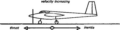
Any imbalance of forces produces acceleration (Fig. 1.2). A model beginning a take off run along the ground accelerates from standstill because the operator suddenly releases it The thrust before release is opposed by the holding force; action and reaction are equal so equilibrium prevails. When the reaction force (holding) stops, the model accelerates. As soon as it begins to move, however, air and ground resistance begin and the faster the model goes the larger these resisting forces become. The model will continue to accelerate only so long as the total resistance remains less than the thrust When the two are equal, with the model flying at some speed, equilibrium is restored (Fig. 1.1c).
In level flight, the weight force acting vertically downwards is opposed by a vertically upwards reaction. This reaction comes, in normal models, from die lift of wings and possibly other surfaces, but it may be supplied by other types of force. A helicopter is supported by its rotors, and a jet-lift aircraft is held up by foe thrust of its motor. If foe upward reaction against weight fails, or is reduced, foe model accelerates downwards. To stop this acceleration it is necessary to restore an upward reaction to equal weight This brings equilibrium but will not stop foe descent To do this an additional force must bring about deceleration. All such acceleration and deceleration will be resisted by foe mass of foe model, i. e. by inertia.
To disturb equilibrium, changing the speed or direction of flight in any way, requires a force variation to bring about an acceleration in the appropriate sense. The second law of
Fig. 1.1 Static and dynamic equilibrium
 |
|
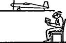
a Body standing on ground; no relative motion: static equilibrium.
 |
b Vehicle moving at steady rate; no acceleration or deceleration: dynamic equilibrium.
d Model climbing, diving or gliding at steady rate and constant speed: dynamic equilibrium.
|
|
|
|
|
|
|
|
|
|
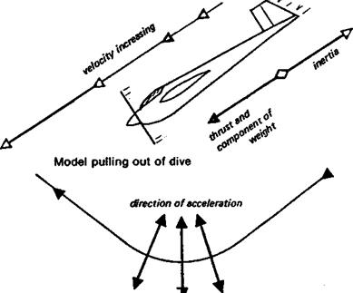
motion states that the strength of force required for any given acceleration depends on the mass of the model. Mass is not the same as weight, although in ordinary language, and on the kitchen scales, the two are often equated. Weight is force exerted by a mass. If a model were taken by rocket to Mars for trials in the atmosphere there, it would, during most of the trip, exert no weight, and on arrival would weigh less than on Earth, because of the lower gravity. The mass would be unchanged throughout, because the quantity of material, balsawood, metal, plastic, glue etc., in the model would be the same. An object of large mass requires greater forces to disturb its equilibrium to any given extent than a small mass. This is sometimes advantageous, as when a model is affected by air gusts. A model of small mass might be overturned by a force that would cause only a minor change of direction with a large mass. But the larger mass also requires a larger force to accelerate it to flying speed from standstill, more force to change level flight to climb, more force to initiate and maintain a turn, and more force to bring the model to a standstill again after flight. Whenever there is a disturbance of equilibrium, i. e. an acceleration or deceleration, or a change of direction, this quality of mass, termed inertia, opposes the change. In a turn, inertia tends to make the model revert to straight flight Turning flight is a form of lateral acceleration. Pulling out of a dive involves a change of direction in the vertical plane, mass resists and tends to make the dive continue (Fig. 1.2).
1.1 LAWS OF MOTION
All aerodynamic theory depends on the laws of motion. These, originally worked out by Isaac Newton, remain entirely valid in engineering providing the matters under discussion are confined to velocities substantially less than the speed of light, and to objects and fluids of ordinary sizes and densities. Quantum mechanics and the theory of relativity, although fundamentally preferable to the Newtonian laws in advanced physics and astronomy, are not necessary for the understanding of model aircraft aerodynamics.
1.2 EQUILIBRIUM
If a body is in equilibrium, it tends to remain so. All the forces acting cm an object in equilibrium are in balance, there is no tendency for it to change its state or accelerate in any direction, or decelerate. This is familiar with respect to things standing on the ground like items of furniture, or a model aeroplane lying on a shelf or workbench, not moving. Such bodies stay put unless something disturbs them, i. e. accelerates them in some way. Moving objects may also be in equilibrium. A model flying straight and level in calm air, neither speeding up nor slowing down, nor turning, is in a balanced state, and will tend to continue moving steadily. The same is true if die model is climbing at a constant speed in straight flight It is in equilibrium even though gaining height, and will continue steadily along its inclined path unless some change of the forces acting on it occurs. Even if the climb is truly vertical, so long as the speed remains steady and there are no changes of direction, equilibrium prevails. In a steady speed dive the same applies (Figure 1.1). Equilibrium, then, is a very common state of affairs. It is a condition of steady motion or rest, in contrast to states of unsteady motion involving acceleration and negative acceleration or deceleration.
The purpose of this book is to present in a practically useful form some standard aerodynamic theory as it applies to model aeroplanes, helicopters and gliders.
‘ Anyone whose interest in aeromodelling is more than casual will benefit from under – 5 standing the behaviour of his models better. He is less likely to make serious mistakes in j, trimming or control, will build better, and may be able to improve the design of models. lApart from these considerations, aerodynamics is an interesting study in its own right and pods a further fascination to the sport.
I Successful models may be designed and flown by rule of thumb. A sort of evolution – Jjtfy survival of the fittest has produced a great many extremely efficient aircraft and it is claimed that this book will bring about any revolution. It is, however, likely that some iw ideas for future development will be extracted by those who read with an open mind. ie of the material contained will be familiar to experienced modellers, but in other they will find their old notions under criticism. This is particularly likely in sions of the basic description and selection of aerofoil sections. Model fliers and іу books and articles written for them frequently adopt a very misleading aerofoil enclature: undercambered, flat bottomed, semi-symmetrical and symmetrical. These s can lead the beginner into serious trouble. At least the camber of the centre line of profile should be known and taken together with the profile thickness.
I The basic layout and trim of nearly all ‘free flight’ models also seems to be dominated fashion to the exclusion of elementary principles. This is not to say that these models not fly well; clearly they do. But trimming them for consistent performance and safety lade unnecessarily difficult when the centre of gravity is in the wrong position relative the mainplane, as it almost invariably is. No gain in performance results, indeed, there ie small performance penalty for slow-flying models if the centre of gravity is located , on current contest-winning models, it usually is. The fact that such models do win ause they are flown very skilfully despite their inherent faults. Arguments in favour this kind of trim, sometimes loaded with mathematical equations, prove on ation to be mistaken.
Other common misunderstandings arise through the confusion between trimming and ibility. This is examined in some detail in Chapter 12.
It is assumed throughout that the reader is a practising model flier and knows at least essentials of how model aircraft are constructed, trimmed and flown. The lematics have been kept to a bare minimum. Where numerical examples have been ight important or interesting enough to merit inclusion, they have been placed in an ndix and may be ignored by those who do not wish to become involved in figuring. It
is rarely necessary or worthwhile in aeromodelling to carry out elaborate calculations; when a little arithmetic is essential it is usually confined to the four basic rules. The underlying principles are emphasised throughout Where a reader is prepared to do a little more work, many of the problems arising can be solved to a sufficient degree of precision by the use of simple graphical methods or at most with an ordinary pocket calculator. It helps to have a few additional functions such as square roots and trigonometrical ratios (Cosines, Sines, Tangents etc.), but these are not essential.
On the commercial market now there arevarious kinds of copiputer software packages with model aircraft applications. These range from glider performance programs to flight simulators and elementary aerofoil section design. (These last should be distinguished from the highly sophisticated programs used for aerofoil design by professional aerodynamicists such as Eppler, Somers, Williams etc. in university and other research institutions.) Modellers using any such packages should remember that they are all based on fundamental assumptions which may be wrong. If garbage goes into the computer, it emerges in the output Even with a sophisticated machine it is most necessary to comprehend the underlying theory if the computer is to produce meaningful results. This book should provide the necessary background enabling the model flier to discriminate between sense and nonsense.
The theories discussed are in general use by aerodynamicists but are not to be regarded і as final truths. There is always room, and in some cases great need, for new discoveries. ; On the other hand, model aerodynamics, like any other branch of engineering science, must be firmly based on fundamental natural principles as these have been found by test and experiment. Some of the most basic principles are examined in the first chapter. Readers already familiar with the laws of motion may wish to skip this early section, though it is important that these passages be understood before the later ones are tackled.
Problems associated with flight and airflow speeds approaching the speed of sound are not considered in this book.
1
In the third edition the main text remains but the opportunity has been taken to include brief discussion of the important wind tunnel research undertaken at Princeton University by Selig, Donovan and Fraser during the years 1986—89. Also an explanation of the effects of wind on model flying has been included since so much misunderstanding surrounds this topic. There is an expanded section on tip winglets and crescent wing planforms. The discussion of the centre of lateral area theory has been expanded and the practice of trimming sailplanes using the so-called dive test is examined in relation to the dangerous phenomenon of ‘tucking under’. The section on air brakes has been expanded to include the ‘crow’ or ‘butterfly’ mix system. A few other minor corrections and additions have been made in the Appendices.
Adelaide, 1994 Martin Simons
The publication of Model Aircraft Aerodynamics in 1978 filled a gap not only in the literature for model fliers but on the shelves of many school and college libraries. The book has proved useful to designers of man-powered aircraft, ultra-light aeroplanes and gliders. Professional aeronautical engineers, researchers and academics, especially those involved with the development of (subsonic) remotely piloted vehicles, found the survey of boundary layer problems contained in the chapters on scale effects and low speed aerofoils particularly valuable as an introduction to this aspect of the subject.
Demand for the book justified several reprints. In the English language at least, it remains the only work of its kind in the field.
The general model aircraft scene has changed remarkably since 1978. Very large models have become almost commonplace. Many of them exceed the old legal limitations and have to be specially licensed for flight. Radio controlled helicopters have become reliable and sophisticated. The emphasis on multi-task and cross country flying for model sailplanes has transformed these aircraft beyond recognition, in ways that were only hinted at in the first edition. Every aspect of model design and construction has been profoundly affected by the increasing use of materials such as carbon fibre, Kevlar, and new kinds of adhesives. Radio control equipment now commonly available is extraordinarily precise and highly reliable. Electric and solar powered models flourish everywhere and begin to rival ‘glow plug’ engined craft. Further developments in gyroscopic stabilising devices and automatic pilots will make these more accessible in future and there is increasing interest in the development of advanced electronic instruments which will inform the pilot, on the ground, of exactly what his model is doing aloft. Microcomputers, now so commonplace, enable modellers, even without scientific or mathematical training, to design new aerofoil sections and optimise the performance of their aircraft by using commercially available software. Models already fly with small computers on board, not to mention surveillance instruments and cameras.
The need for a new edition of this book became increasingly apparent as die years passed. The basic theory has not changed, but the author has corresponded with many model fliers in many countries. These discussions have indicated to him some passages which were ambiguous or over-simplified in the original. There have been numerous small improvements of wording in the interests of greater clarity and emphasis. Some chapters have been re-grouped or re-arranged to improve the logical sequence. Many more sub-headings have been added to break up and make more legible what is, inevitably, a fairly solid text.
Substantial re-writing has been done in the chapter on trim and stability, not because the first edition was wrong but because a more emphatic statement seems necessary in an. area where much confusion remains even among very experienced modellers.
I A new section on winglets and tip sails has been included. The veiy brief notes about
wind tunnel testing (in the first edition only part of an Appendix) have now been expanded to a full chapter with some advice on the use of the data coming from various small wind tunnels now operating in several countries.
A new chapter on propellers has been added, since their omission from the first edition drew some criticism. It must still be admitted that a full treatment of this subject would require a different book, but, since the adoption of the turbo-jet engine for full-sized aircraft, there is a notable dearth of modem textbooks on the basic principles of propeller design. Some of the most prestigious libraries consulted were unable even to find the basic works on propellers which, once, were required reading for every student of aeronautics. The need for a very simple explanation seems quite pressing, and in a very limited space, it has been attempted here.
Helicopters too, require books to themselves, yet very little about the aerodynamics of rotors has appeared in a form suitable for the model flier. The final chapter of this edition can pretend to be nothing more than an outline sketch of some theoretical aspects of these extremely complicated devices. It may at least point the interested reader in the right general direction for further studies.
Apart from these changes, wherever possible the results of recent research have been incorporated in amplification and confirmation of the text. Much still remains to be investigated.
London 1986 Martin Simons
The author wishes to thank the many people who helped, sometimes without their knowing it, in the preparation of this book and the new edition. Some of them are aeromodellers whose questions and comments suggested the need for such a work in the first place. Since the publication of the first edition there has been much correspondence and many discussions with model fliers. The author has spoken and answered questions at a good many meetings, formal and informal, at places as far apart as rainswept hilltops in England and dry paddocks in Australia. It is hoped the revised text will stimulate as much thought and interest as the original did. Special thanks are owed to those who challenged some of the statements made or pointed to obscure passages requiring better wording.
Among the constructive critics who have helped with preparation of the revised edition are Noel Falconer, who supplied several pages of most valuable written commentary, Stan Hinds, Freddy Jones and Hans-Julius Schmidt. The new text should accommodate their points. Frank Irving’s kind assistance with the first edition has not been forgotten.
Thanks are owed again to Professor Eppler and Professor Wortmann (who died, most sadly, in 1985), and to Dr. Althaus, for permission to use some of their most recent research material. Rolf Girsberger supplied ordinates of his latest aerofoils for inclusion in Appendix 3. Thanks are also due to Michael Selig and Martin Hepperle.
Ron Moulton encouraged the author at all stages in preparation of the first two editions. Thanks are due now also to Beverly Laughlin and Lyn Corson of Argus Books for their help with the third edition.