Our heavyweight helicopter equal in the world does not have
In Rostov started production of the most load-lifting rotary-wing car The Russian holding «Helicopt[...]

Everything about aircrafts and helicopters. News and events in aviation worldwide. Civil, transportation, military helicopters and airplanes.

Everything about aircrafts and helicopters. News and events in aviation worldwide. Civil, transportation, military helicopters and airplanes.

Everything about aircrafts and helicopters. News and events in aviation worldwide. Civil, transportation, military helicopters and airplanes.

Everything about aircrafts and helicopters. News and events in aviation worldwide. Civil, transportation, military helicopters and airplanes.


A wing with no dihedral is neutrally stable in roll. Any roll which starts will be damped out, but there will be no tendency to correct the attitude of the model once the roll has been arrested. If one wing is down, it will stay down. Damping in roll has already been mentioned in Chapter 4 (see Fig. 5.9). As the wing rolls, the down-going wing meets the. air at a greater angle of attack while the angle of attack of the up-going wing is reduced by the same amount. There arises an imbalance of lift on the two sides, which tends to bring the roll to a stop. Once the roll does cease, the angle of attack of each wing is the same, so no tendency to return to level flight is present. The model, canted over at an angle,
sideslips.
It is sometimes suggested in the modelling press that dihedral operates to stabilise a model as indicated in Figure 12.17. In level flight the weight, acting vertically down, is supported by the vertical component of lift on the two wings. Since the wings are set at a dihedral angle, the actual lift force has to be resolved as shown, into a relatively large vertical force and a small horizontal component acting inwards. If the model is canted Over by a gust, one wing tends more toward the horizontal position and the other is at a steeper angle. As the diagram shows, the vertical component of the lift on the down side is then larger and that on the higher side, smaller. A corrective restoring moment appears tending to roll the model back to level flight again.
 |
Unfortunately, this explanation, although sufficing for small and momentary disturbances, is far from adequate. In a more complete explanation, not only the lift forces but the weight too must be resolved into one component acting at right angles to the axis of the aircraft, the other then slanting toward the down-wing side. This creates an unbalanced situation. As soon as any such banking occurs, the model will begin to sideslip towards the lower wing. The sideslip changes the angles of attack of the two wings differentially and it is this which provides the powerful, corrective rolling force of dihedral.
Figure 12.18 shows how, in a sideslip, the angle of attack of the into-slip wing is increased and that of the other decreased. The lift on the into-slip side increases and a rolling force appears. Any increase of lift coefficient on a wing also increases the strength of the vortex at the tip. Hence in a sideslip, the dihedral not only creates a strong rolling force to raise the into-slip wing, but a drag force also appears tending to yaw the aircraft towards the slip – a yaw one way, combined with a rolling force the other. Correction of the yaw depends mainly on the weathercock stability, which is why dihedral and fin areas are so closely coupled.
The yawing effect of dihedral in slipping or skidding is similar to the adverse yaw of ailerons, which will be discussed below (Chapter 13).
Unfortunately, such a combination can lead to the converse of lateral instability, which is spiral instability. This arises if the fm area is too large relative to the dihedral. The initial small side-slip causes a strong weathercocking yaw. The dihedral, being slight, provides very small or no counter-rolling force, and the decrease of airspeed on the inner wing of the yaw causes that wing to drop. As mentioned in the next chapter, a similar effect arises when a model is yawed by means of the rudder control. With a spirally unstable model, the wing drop caused by the yaw is sufficiently sharp to increase the side-slip. The fin then attempts to weathercock the model further, and the wing drop again is too much and the sideslip continues, the bank angle increases and the model enters a turn which tends to tighten into a spiral. Since, as the angle of bank increases, the yaw relative to the ground becomes increasingly nose-down in direction, the spiral turn becomes a spiral dive at increasing airspeed, the bank angle approaches the vertical and the inertia loads on the wings rapidly multiply so that, if the model does not hit the ground first, the wings or tail are likely to break.
![]()
 |
Fig. 12.16 Spiral instability
High powered duration models are particularly prone to spiral instability since they are usually trimmed for a spiral climb and it is very easy for such a climb to become a spiral dive. To prevent this, fins are small and dihedral large, even at the cost of some Dutch rolling tendency. Free flight gliders generally, while less critical in this respect, tend in the same direction since while the Dutch roll is unpleasant and inefficient, it is comparatively safe, whereas the spiral dive invariably leads to a broken model. Radio controlled models, however, are usually spirally unstable to some extent As with full-sized aircraft, the early stages of a spiral dive are easily recognised and corrected, the dive does not build up immediately. As the nose begins to drop, a slight correction is given on the elevators, together with rudder and ailerons to check the yaw and roll. The Dutch roll, on the contrary, begins quite suddenly and, once started, is hard to stop because the pilot’s reactions are likely to be slow. It is even possible for the correcting control movements to be in phase with the oscillations, tending to increase them rather than damp them out The pilot recognises the yaw and roll a short time after they begin, and a moment later applies the controls to correct the condition. But by the time they take effect, the aircraft has already reached the limit of its swing in one direction, and the counter-movement in the other direction has begun. The pilot’s effort then helps only to make the next swing more violent, and when, after a momentary delay he realises this and moves the controls the other way, the aeroplane Ijas already passed through its maximum oscillation and again, the control movements make the condition worse. The pilot’s best hope is to centralise the controls and wait in the hope that the model has enough natural stability (i. e. enough fin area) to damp down the oscillation of its own accord. Another technique which often succeeds is to move the elevator control forward for a faster flight speed. This changes the wing lift coefficient and hence the forces at work may be damped.
The designer’s difficulties are increased by the fact that a model which is both spirally and laterally stable at one airspeed will not be so at all speeds. At high angles of attack spiral stability is very difficult to achieve. It requires generous dihedral on the wing, and quite small fin area, as on ‘duration’ models. At high speeds, however, the dihedral is too much and there is a tendency for such models to oscillate from side to side. The fin area needs to be larger to damp out oscillations. This tends to cause spiral instability. Fortunately, most models are designed mainly to fly at one speed, and a stable ‘one speed’ model is not impossible. For R. C. sailplanes, and powered duration models, which fly at varying speeds, there is no solution for all conditions. If the model is primarily a thermal soarer which will spend most of its flight time circling, effort should be concentrated on spiral stability – large dihedral with smallish fin. This will usually mean some tendency to wander and swing from side to side during ‘penetration’ glides or climb under power at high speeds. For the hill-soarer, long periods of circling flight are unusual, so spiral stability is less important. The fin area may be increased and dihedral reduced. Turns can be controlled carefully to check the tendency to develop a spiral dive. If control is by rudder only, however, dihedral must be quite large.
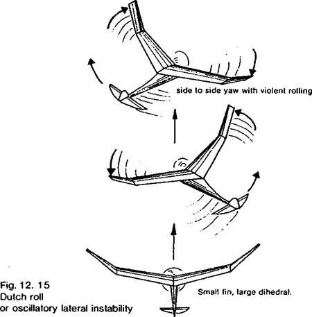
If the fin area is too small and the dihedral large, a ‘Dutch roll’ or lateral oscillation results. The model, if disturbed by a side gust, tends to sideslip. The dihedral responds to this, as shown in Figure 12.15, by rolling the model against the sideslip, raising the ‘into slip’ wing. The fuselage, however, with too small a fin, tends to turn broadside to the flow. The initial small sideslip thus becomes a yaw increasing the slip combined with a roll away from it and the tendency increases until the wing may be rolled almost to the vertical
|
|
while the fuselage is at a considerable angle to the original flight direction. In this state, the fuselage yawing force, having achieved a more broadside-on attitude weakens, but the model is steeply banked. The result is a return sideslip in the opposite direction. The
dihedral responds to the change by rolling the wing back the other way, the fuselage attempts to turn broadside to the new slip direction and the model begins a wild oscillation from side to side rolling and yawing with the tail swinging wildly through an arc. The cure is to increase fin area or decrease dihedral, or both. The model with adequate fin power then yaws into sideslips, it has so-called weathercock stability. The dihedral, when the model is stable, is not so pronounced that it raises the into-slip wing very much. The ‘model responds to a side gust with a mild yaw into the gust with only a very slight roll. The requirements for lateral oscillatory stability are thus large fin area with small dihedral.
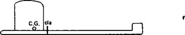
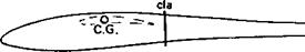
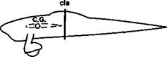
The cardboard cut-out method described in Fig. 12.13 for finding the neutral point for longitudinal stability resembles a method which is still sometimes advocated for determining the size of fin required on a model. This was originally suggested in its simplest form in Frank Zaic’s 1934 Yearbook. A side view of the model is drawn to scale on card, cut out and balanced to ensure that the so-called centre of lateral area falls behind the centre of gravity. If not, the fin area is adjusted until it does so. Unfortunately this method, although attractively simple, is based on a misunderstanding of the behaviour of fuselages. As mentioned above, a long slender body like a fuselage tends to turn broadside on to the airflow. Without a fin the fuselage of an aircraft will tend to turn the whole aircraft in this sense also. However long the fuselage, it will not naturally align itself with the direction of flight. As Fig. 12.14 shows, if the theory in this form is applied it indicates that no fin at all is required on most models, which is easily disproved by trying to do without one. This still occurs in most cases if the projected dihedral area is included in the cutout. Dihedral does have an important influence on lateral stability but if the fuselage is of normal length the simple method still suggests that the fin may be dispensed with in many cases, which is not so. From these results it is hard to believe that any successful model has ever really been designed by this 1934 method.
An elaboration of the c. I.a. theory was due to Charles H. Grant and described in his book, Model Airplane Design published in 1941.[3] The concern at that time was with free flight engine powered models for which high reserves of spiral stability were essential. The cardboard cutout is prepared as before but the dihedral and any other parts of the model which are duplicated on right and left sides (such as the undercarriage and wheels, or twin fins) are doubled in card thickness. The balancing procedure is then gone through and the c. I.a. located. This point should, according to Grant, lie on a horizontal line through the centre of gravity with the model in a level flying attitude, and about 30 to 35 % of the distance from the c. g. to the aerodynamic centre of the vertical tail surface. Further work was required to find the centre of lateral areas ahead of and behind the c. I.a. of the whole, and the line joining these was termed the displacement axis. A good deal was thought to depend on the precise relationship of this axis to the c. I.a. as a whole and to the centre of gravity.
If Grant’s methods are adopted, and some designers do still use them, successful models result. They turn out as a rule to be very similar in general layout and appearance to many other satisfactory models of similar general proportions, including canard designs and models with large floats for operation from water. Applied to aircraft of different proportions, especially to advanced modem sailplanes, aerobatic and pylon racing power models, the results turn out rather differently, especially if long, slender fuselages are used and if there is no wing dihedral.
It is probably fair to conclude that while the c. I.a. method produces safe models resembling many others already known to be satisfactory, it is nevertheless based on a shaky theoretical foundation and should not be relied on if anything much out of the ordinary is proposed.
The correct size of fin for a model can be computed by methods sometimes used in full – sized studies, but the work is lengthy and the results still not always reliable. Previous experience and trial are better guides, with a background of general theory to direct
|
|
|
|
|
|
|
|
|
|
|
|
|
|
|
|
|
![]()
experiments. The main principle is that fin and dihedral do need to be considered together. In practice, quite large variations in the size and disposition of the vertical tail areas are possible without greatly upsetting the control and handling of a radio controlled model.
Free flight duration engine-powered models sometimes instead of climbing steeply and fast, ‘go flat’ and fly very fast, more or less he rizontally or at a shallow angle of descent, to hit the ground.
It seems very likely that the cause is the same as that of the ‘tucking-under’ glider. These models frequently have the static margin reduced by aft centre of gravity location. Under power, a static margin that may be adequate for gliding or climbing may be reduced so that the model verges on neutral stability. Some flights then may succeed but on occasions a minor variation in launching technique may bring the model to a dangerous condition.
12.16 SPECIAL PROBLEMS: VERY SMALL MODELS
Very little is known about airflows at Reynolds numbers verging on, or below, the critical. where the flow tends to separate completely from the wing. In some small modefs it seems the flow may change abruptly from one condition to the other more than once during a flight. This seems particularly likely with ‘chuck’ gliders which are launched fast and are at relatively safe Re number during the initial stages of a flight, but which slow down fairly rapidly and may then fall into a sub-critical state. Once in this condition they may not recover, in which case a very poor flight results. Associated with the flow break away there is a change of pitching moment which upsets the normal stability. The likely solution to such problems is to increase the wing chord and use an aerofoil which is not badly affected by low Re numbers. Probably the closer the profile comes to a flat plate section the more consistently it will behave, although performance in the absolute sense is likely to sufTer.
Quite different stability problems appear with indoor, microfilm covered models. These are so flimsy in structure that distortion under flight loads is commonplace. The uneven unwinding of rubber motors also can cause serious shifts of centre of gravity position during a flight, which upsets both balance and stability. Humidity and air temperature also make differences which affect other models very much less. It becomes practically impossible to work out static margins or even trimming angles, since in flight these change. Even with all these effects, it still seems that a centre of gravity that is at least in the right place to start with will improve stability and hence consistency. There is no advantage, apparently, in using ‘lifting’ tailplanes of large area, when, by adding the excess area to the wing and moving the c. g. forward, stability would be improved without loss of aerodynamic efficiency.
Radio controlled sailplanes sometimes run away out of control in a dive, which steepens rapidly until, despite full up elevator the model is vertical and even beyond. Quick thinking by the pilot can sometimes save the situation by pushing the stick forward and so helping the model through the ‘bunt’, to emerge at high speed in level flight, but inverted. The strains of such a manoevre may cause structural failure, but if not the model may be saved.
The cause is almost certainly lack of static margin. That is to say, the centre of gravity should be moved forward and the tailplane re-trimmed to improve static stability. This seems difficult for some model fliers to grasp, since they tend to equate a nose-down pitch with too great a weight in the nose of the model. The foregoing discussion of balance should disabuse them. If the model is balanced in straight and level flight, by suitable tail trim angle, it will still be balanced in a dive, but if the c. g. is too far aft it may lack stability and tuck under with elevators up.
Another very likely cause is structural flexibility. The models which exhibit this tendency are often lightly built and have strongly cambered wings. The camber increases the negative pitching moment and if the tailplane and rear fuselage are somewhat flexible, or if the control rods and linkages are sloppy, there may be enough distortion to reduce the stability of the model to a dangerous extent when it is flying fast, as in a shallow dive. The wings twist also, as the pitching forces increase, and they may break or flutter. The discussion of stability above, it should be remembered, assumed a rigid structure (12.14).
A method of trimming a model sailplane which has been widely advocated is the so-called ‘dive test’. This is not to be recommended although some pilots evidently like the feel of models which have been set up in this way. Following the dictates of the dive test generally increases tail drag and so tends to spoil the all round performance of the model slightly, though probably not enough for this to be apparent to the pilot. More importantly, it may reduce die inherent stability of the model to die point where a runaway ‘tuck under’ is more likely. Some models have in fact been written off in ’tuck under’ accidents during attempts to follow the dive test procedure.
In brief, the dive test, as described in some publications, requires the model flier to put the sailplane into a steep dive of about 60 degrees and hold it there for several seconds to allow the airspeed to build up. Obviously this has to be done when the sailplane is at a considerable height. The controls are then returned to neutral and the model is observed to see how it responds. That is, the elevator is first set for diving and held for a count of five to ten seconds, then it is returned to the position for level flight.
The question is whether or not the sailplane will obey the controls. Advocates of the dive test evidently prefer a model which does not respond normally. What they seek is a model which continues in the steep dive even when the elevators are in the neutral position. To achieve this they progressively move the centre of gravity aft, reducing the stability of the model until this result is arrived at. A model which does in fact behave this way is on the verge of tucking under.
A stable model will respond to the elevator in the normal way. That is, when the elevator is moved from the diving position to the level flight trim, the model will obey and pull out of the dive. Because of the excess airspeed of course the model will not return instantly to level flight but will over-correct — the nose will rise beyond the horizontal, followed by the usual stable oscillating, nose up, nose down, response which the pilot should have no difficulty in smoothing out to restore level flight. Such a response is perfectly normal and safe.
• The model which does not pull itself out of a steep dive with the controls central, is neutrally stable and in a very dangerous condition. Such a trim is not the trim for least drag (see section 12.8 above).
As explained above (sections 12.12 and 12.20), the stability of a model is entirely under the control of the operator and can be adjusted by moving the centre of gravity, i. e., by adding or removing ballast from the nose. Such changes have an immediate effect on the sensitivity of the elevator. Some pilots prefer a docile model which does not require constant attention, once trimmed for a particular airspeed. Others prefer more sensitivity and may move the c. g. aft slightly to achieve this. But to move the c. g. so far aft that the model no longer pulls itself out of a steep dive with neutral controls, is asking for trouble.
Depending on the methods used to calculate the position of the neutral point and the various allowances made for tailplane efficiency, fuselage effects, etc, estimates of the. size of the static margin required for adequate, but not excessive, stability vary a good deal. However, when the static margin is worked out, it is usually expressed as a decimal fraction of the mean wing chord. It is then usually found that a satisfactory s. m. comes out less than 0.2 mean chords, for radio controlled power models. Much greater figures than this suggest too much stability for satisfactory control response and much less begins to approach ‘twitchiness’ which may nevertheless suit an aerobatic model. For most free flight models, higher margins are required as a rule. If only wing and tail areas and moments are taken into account, the static margin should be on the generous side to allow for the other factors. As already noted, the degree of stability any particular pilot requires depends to a large extent on the kind of model and flying done, and the centre of gravity position can be adjusted to suit personal preference.
12.15 SPECIAL PROBLEMS. DEEP STALLING
The T-tail configuration has several aerodynamic advantages in normal flight attitudes, but it may in some circumstances lead to a trouble known as deep stalling. In jet airliners, an example is the ВАС 111 prototype which crashed, killing all on board, in 1963. The aircraft lost most of its forward speed and descended in a flat attitude. Model aircraft with ‘tip up tail’ dethermalisers are placed in this deep stalled condition deliberately to bring them down, but some T-tailed models may do the same thing when the modeller does not intend it, and the controls may be incapable of returning the model to normal flight The cause is quite complex. As the main wing approaches the stall, the wake becomes broader and at the same time the tailplane, because the nose of the model is rising, comes down into the wake and loses efficiency. If the centre of gravity is rather too far back, this also contributes to the undesirable nose-up pitch. When the main wing is stalled, the wake tends to strike the whole tailplane, whereas a low mounted tail will be out of the wake and will be more efficient than usual. Once in the deep stalled condition, the model may be unable to get out of it because the airflow over the ftiselage, or engine nacelles mounted at the rear, causes the formation of strong rotating vortices similar to those at the tips of a lifting wing. Given a bad combination of circumstances, the downwash caused by these vortices may strike the high tail and keep it down in spite of the pilot’s efforts to restore forward flying speed. The problem is baffling unless the modeller understands the cause, since an aircraft that flies perfectly well most of the time may without warning fall out of the sky and pancake, with fuselage more or less horizontal and hardly any forward velocity. After repairs, the same model may fly satisfactorily again for some time without ‘deep stalling’. On the other hand, in gusty weather or in aerobatics, the trouble may strike at any moment (the ВАС 111 prototype that crashed had completed many hours of successful test flying before the accident) The cure may be simply to return to an orthodox low tailplane configuration, but the tailplane will then probably need to be enlarged to cope with normal flight stability requirements. Other possible modifications that might be effective include increasing tailplane span with or without an increase of area, or adding dihedral to the tailplane, both with the object of getting some of the tail area out of the downwash from the fuselage vortices. Carrying the tail still higher would have the same effect but might be impossible for structural reasons. Moving the centre of gravity forward and re-trimming may also help and will in any case improve stability in normal flight, so reducing the danger of stalling in the first place. The fuselage may be modified in an effort to reduce the strength of the downwash. A broad fuselage is more likely to give trouble than a slender one, and engine pods or nacelles have a bad effect in some positions, especially just ahead of the tail unit Either lengthening or shortening of the fuselage may change the relationship of tailplane to vortices enough to solve the problem. Once the model is deep stalled, none of the controls except possibly wing flaps have much effect. The elevator tends to be useless and may even be forced upwards against the stops. The ailerons on a ‘super stalled’ wing are totally ineffective, and the redder is not powerful enough to roll the model out of its horizontal position. It might be possible to yaw the model and the fuselage vortices might then clear one side of the tailplane. The application of engine power is usually not enough to restore the situation.
Wing flaps, however, may give a sufficiently powerful nose-down pitching moment to overcome the tail downwash effect On the other hand, air brakes or spoilers may create more vortices or a more turbulent wing wake and make things worse. A model fitted with a tail parachute can be saved from the deep stall; the ’chute when deployed slows the model still more, the whole thing then hangs nose-down from the supporting parachute, and after a few seconds normal flight may be resumed with the parachute jettisoned.
The aerodynamic centre of a biplane, or other multiplane wing arrangement, may be roughly worked out by assuming that the two, or more, wings can be replaced by a single equivalent surface which will have its aerodynamic centre on a line joining the quarter chord points of the two (or more) wings. It will lie on this line at a point determined by the relative efficiencies of the wings and their areas. The lower wing of a biplane is usually somewhat less efficient than the upper wing, so if two wings are of equal area and span, the combined a. c. will be slightly nearer the upper wing. With a sesquiplane, the combined wing a. c. will of course be much nearer the larger top wing than the smaller bottom one, and so on.
With a tandem, the rear plane may be treated exactly as a tailplane, for determination
|
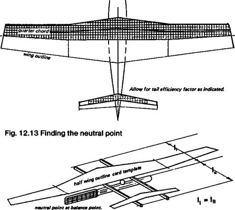
1. From an accurate scale drawing of the model in plan view, make stiff cardboard templates of the front half of wing and tailplane. Use identical weight card for both. 2. Mount templates on two stiff, light balsa strips and find balance point. Trim balsa strips by trial and error so that 1 ш l^when balance point found. 3. Check overdrawing. C. g. of modal must be ahead of neutral point as found above. |
of the neutral point position. The fact that it shares the lift load makes no difference in this respect the centre of gravity must still be in front of the combined neutral point, for stability.
The effect of the fuselage is destabilising. Any long, slender body moving through the air tends to turn broadside to the airflow. This can easily be confirmed by experiments with throwing sticks and arrows. Even the addition of a weight at one end does not change this much. As any archer will confirm, arrows which lose their fletching will yaw wildly sideways in flight Rockets and bombs require fins for the same reason. The fuselage therefore must be regarded as moving the neutral point forward of the location determined by wing and stabiliser alone. In full-sized work, attempts are made to estimate this numerically, but the upshot is invariably that the static margin must be large enough to cope with die fuselage effect That is, the centre of gravity must be far enough forward to achieve the desired stability, whatever may interfere. The propeller also has a destabilising effect which is considerably greater with power on than when the propeller is stationary or feathered. There is usually a difference in stability power on and power off, which is caused by this, among other factors.
Every other component of the aircraft which has air flowing over or through it will exert some influence on the neutral point position. For instance, a large horizontal undercarriage axle, faired, ahead of the centre of gravity, will tend to destabilise, but a broad strut, bracing a tailplane, will act in some respects like a second tailplane. Ultimately, the static margin has to be adjusted to cater for all these factors to produce a satisfactory result
The distance between the centre of gravity and the neutral point is termed the static margin of the aircraft. It gives a very useful standard of comparison of one aircraft with another, since if they have similar static margins they will have similar static stability. The larger the margin, the greater the stability. This concept also brings into emphasis that a shift of the centre of gravity of any model aircraft can change the stability margin. By this very simple means a dangerously unstable model can be made stable, or an over-stable one made more sensitive and responsive. Stability is thus almost entirely under the control of the model flier and can be varied, within limits, by the addition or subtraction of ballast at nose or tail. Any such change of ballast of course will require a new trim. setting.
12.14 LOCATION OF THE NEUTRAL POINT
As just mentioned, the model flier does not actually need to know where the neutral point of his aircraft is, because stability can so easily be adjusted by careful use of ballast
Fig 12.11 Stable layouts: C. G. ahead of N. P.
|
/ CG |
 |
/
However, it is useful and interesting to know how the neutral point may be found if a new model is being designed or if two models are being compared.
The most important determinants of neutral point position are the mainplane and the tail or foreplane. Any lifting surface ahead of the centre of gravity will naturally tend to move the neutral point forward and so* is destabilising. This applies to canards. The foreplane causes the neutral point to lie ahead of the mainplane’s aerodynamic centre, so a centre of gravity position like that of Figure 12.4 is unstable. For stability, the canard must have the c. g. forward as shown in Figure 12.11c. Thus, the foreplane of a stable canard carries, for trim, not only the camber induced pitching load, but an additional load caused by the forward c. g. Any surface behind the centre of gravity, such as a tailplane, has a stabilising effect, since it brings the neutral point aft. Unfortunately, the efficiency of the tailplane is adversely affected by the wing, especially if it lies in the wing wake or comes into the wake at some angles of attack. Despite this, a useful measure of the tailplane’s stabilising effect may be obtained by working out the stabiliser volume coefficient
Fig. 12.12 Unstable layouts C. G. behind N. P.
a Orthodox layout
The formula relates the tail volume to the wing and fuselage length:
у _ Ss x Ls Sw x c
Here, Vs is the tail volume coefficient, Ss and Sw are tail and wing areas respectively, Ls is the distance of the tailplane’s quarter chord point from the wing’s aerodynamic centre (allowing for any sweep of either surface), and c is the mean wing chord (Sw/Span). Strictly, the coefficient so found should be reduced by some factor to allow for loss of tail efficiency. A high-mounted T tail may be as much as 90% efficient, a low tailplane behind a fattish fuselage, in the wake from the wing, may be only 50% efficient. Some guesswork is involved in making such estimates. For a canard the same formula may be used to assess the de-stabilising effect of the forewing.
Various ways are used to calculate the position of the neutral point, using the wing and tail alone and ignoring any other effects. A way of doing this without calculation is suggested in Figure 12.13. Such crude methods are of course only approximate. A method of more exact calculation appears in Appendix 1.