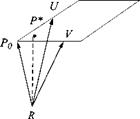
A plane of symmetry has the characteristics of a mirror. The left side repeats the right side. Any aircraft exhibits this reflectional symmetry—what ever happened to the oblique wing? Even right-hand maneuvers can be reflected into left-hand maneuvers just by geometrical manipulation. The tensor that makes this happen is called the reflection tensor M.
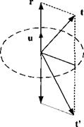
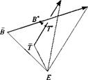
What are the characteristics of this tensor M that reflects the vector t into t’ by the mirror plane with unit vector и (see Fig. 2.20)? First, project t onto и with the projection tensor P = ий to get r = Pt and then derive t’ from the vector triangle
t’ = t – 2r = t – 2Pt = (E – 2P)t
The reflection tensor of the mirror plane with unit normal к and unit tensor E is therefore
M = E – 2km (2.26)
It is not only symmetric but also orthogonal, as we can demonstrate by
MM = (E — 2 ий)(Е — 2км) = E — 4кк + 4мм km = E
The reflection tensor plays an important role in Chapter 7, where we will sort out the existence of higher-order aerodynamic derivatives of airframes exhibiting reflectional symmetry. If the mirror plane is oriented in body coordinates }R such that its unit normal has the coordinates [й]в = [0 1 0] (right wing of aircraft), then the reflection tensor has the coordinates
|
|
0
|
O’
|
|
‘0
|
0
|
O’
|
|
‘1
|
0
|
O’
|
|
[M]5 = [E]B -2[uf[uB =
|
0
|
1
|
0
|
-2
|
0
|
1
|
0
|
=
|
0
|
-1
|
0
|
|
0
|
0
|
1
|
|
_0
|
0
|
0
|
|
_0
|
0
|
1
|
We conclude that the reflection tensor changes the sign of the second coordinate, but keeps the other two coordinates unchanged.
Example 2.9 Application of Reflection Tensor
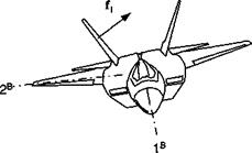
Problem. An aircraft (see Fig. 2.21), with a canted twin tail, executes a pushdown maneuver. What is the resultant force of both control surfaces / if the force on one surface is/,? Derive the equations in invariant form and then introduce body coordinates ] .
Solution. We use the reflection tensor to determine the force on the other control surface and add both together
/ = /і + /2 = /1 + Mfx = (E + A#)/i = 2(E – P)fl
With the unit normal of the mirror plane being к
|
f = 2(E – km)/!
|
This is the desired result in symbolic tensor notation. Introducing body coordinates for the unit normal [й]в = [0 1 0], and for the force on the right control surface [/J® = [0 /12 /13] yields the result
|
■1 0 cr
|
– 0 –
|
|
– 0 –
|
|
2
|
0 0 0
|
/12
|
= 2
|
0
|
|
0 0 1
|
-/із.
|
|
-/l3_
|
We find that the horizontal force components cancel, and the vertical component is doubled by the second surface.
2.4 Summary
If you are reading this, you have persevered until this chapter’s end. We are indebted to the physicists of the 18th and 19th centuries for the foundations of classical mechanics. Its axiomatic treatment puts our modeling tasks on a sure footing. Simple Cartesian tensors in Euclidean three-space are the symbolic language, and their realization as matrices by coordinate systems are the fodder for computers. I hypothesized that points and frames suffice to model flight mechanics—a statement that still needs verification. Some of the cherished traditions of vector mechanics had to be abandoned. Coordinate systems have no origins, and the radius vector has no place in our tool chest.
Then, with the help of tensor algebra we assembled some basic operations. The scalar, vector, and dyadic products are essential for general modeling tasks, and they are applied to specific geometric problems. Some of them we readied for the toolbox: straight line, plane, normal form of plane, plane projection tensor, and reflection tensor.
Needless to say, but worth emphasizing, we just got started! There is so much more for you in store. Although we already introduced frames and coordinate systems, we need to dig deeper. I shall attempt to clearly delineate their distinctly separate purposes in the next chapter.
References
‘Hamel, G., “Die Axiome der Physik,” Handbuch der Physik, Band 5, Springer-Verlag, Berlin, 1929, Chap. 1.
2Noll, W., “On the Continuity of the Solid and Fluid States,” Journal of Rational Mechanical Analysis, Vol. 4, No. 1, 1955, p. 17.
3Truesdell, C., and Noll, W., “The Nonlinear Field Theories in Mechanics,” Handbuch der Physik, Vol. III/3, edited by S. Fluegge, Springer-Verlag, Berlin, 1965, pp. 36, 41, and 42.
4Ricci, G., and Levi-Civita, T., “Methodes de Calcul Differentiel Absolu et Leurs Applications,” Mathematische Annalen, Vol. 54, 1901.
5Einstein, A., “Die Grundlagen der Allgemeinen Relativitaetstheorie,” Annalen der Physik, Vol. ‘4, No. 49, 1916, pp. 769-822.
6Duschek, A., and Hochrainer, A., Tensorrechnung in Analytischer Darstellung, Vols. I, II, and III, Springer-Verlag, Berlin, 1968, 1970, and 1965.
7Wrede, R. C., Introduction to Vector and Tensor Analysis, Wiley, New York, 1963.
8Betten, J., Elementare Tensorrechnung fuer Ingenieure, Vieweg, Brunswick, Germany, 1977.
Problems
2.1 Scalar triple product. Show that the scalar triple product V = (Xy)z = yXz is the volume contained within the three vectors x, y, and z by using scalar and vector products. For the body coordinate system ]B the vector coordinates are [x]B = [8 -2 -3], [y]B = [3 14 1], and [z]B = [3 -2 10] m. What is the value of V?
2.2 Helicopter landing aid (Example 2.6). Refer to Fig. 2.15, the helicopter landing patch, to visualize the following numerical measurements: [sb0h]g = [-22 -10 121], [Svh]g = [—12 16 124], and [їсзд]° = [9 -5 116]. Calculate the displacement vector of projection В wrt the helicopter H, {sHH]G with the equations derived in the example. (Numbers are in meters.)
2.3 Parallel lines. Determine the equation of a line [spR]R = usup„]k -f – [.?/>„«]B that intersects the point Po, given by its displacement vector [sp0r]r = [1 2 3]. This line is parallel to another line [sqr]r = u[l 1 1] + [1 0 0]. The coordinate system ]R is arbitrary (Solution: [Spr]r = [и + 1 и + 2 и + 3]).
2.4 Intersecting lines. Determine the point of intersection I, [5/л]в, of the two straight lines with the same reference point [5pr]b = и[1 1 l] + [0 1 0] and [sqr]b = r[0 1 1] + [1 1 0]. (Hint: Two lines intersect if there exist и and v such that [sbr]r = [«ек]в.) Complement the sketch by a three-dimensional scaled figure. The coordinate system ]R is arbitrary (Solution: [5/r]r = [1 2 1]).
2.5 Closest distance to a line. Determine the point P*, Sp*r, on the straight line SpR = uS(jp0 +spoR that has the shortest distance from R. (Hint: Find u* such that SprSpr is minimized.) Derive the general equation first, then apply it to the example [sm?]r = u[0 2 l] + [0 0 1]. Make a three-dimensional sketch. The coordinate system ]R is arbitrary (Solution: [л>.д ]л = [0 —2/5 4/5]).
2.6 Closest distance to a plane. Determine the point P* of the plane sPR = usup0 + vsVp0 +sPop that has the shortest distance from R. Procedure: Let u* and v* be the parameters of the point P* in the plane that is closest to R and show that
_ S VPos UP0S PqrS VP0 — s VPos VP0S paRS UP0 W — 2
s UPos UP0S VPos VP0 — (Svp0SUP0)
_ S UPos VPpS PqRS UPq — s UPQS UPqS p0rS yp0
s UPos UP0S VPos VPo — (s VP0S UPa)
by minimizing sprspr with respect to и and v.
2.7 Projected angle on focal plane array. A building is imaged on a focal plane array. Two unit vectors t and t2 model the sides of the building, emanating from one of the rectangular comers. The normal unit vector of the focal plane array is u.
(a) Derive the tensor equation that allows you to calculate the angle ф between the two sides as seen on the focal plane array.
(b) Calculate ф from the numerical values:
ft]G = [l 0 0]
[h]G = l 0 1 0]
[u]G = [0.648 0.3 0.7]
(Solution: ф = arccos(j^pl^), where N = E — ми).
2.8 Miss vector in target plane. Given the target plane P and its associated coordinate system ]p with its I p, 2P – axes parallel to the surface. The point target T is contained in this plane. The missile’s last two calculated positions are at В and
B. Derive the miss vector [л д. у ]р with B* the penetration point. By interpolating the straight line [s5b], you should obtain
[sa*r]P =
SBB) 3
Furthermore, derive the intersection time tB. with the target plane, if the time tB and the integration interval At are given (assume constant velocity):
You will need these two equations for any simulation that models the intercept of a plane. Air-to-ground and air-to-ship missiles are typical examples. For most of these applications, the linear interpolation of the intercept point is adequate. You will find them implemented in the CADAC simulation CRUISE5, Subroutine G4.
 в
в
t— 2P
/ /’ B>"’
3P/ 2P
2.9 Closest approach of two lines. Determine the displacement vector sB-r> of the closest approach of a missile c. m. В and a target T by linear interpolation of the last two integration steps. Assume that both velocities are constant during the integration interval Af. First, derive the time of closest approach t* = tB + r by minimizing subject to the elapsed time r,
f* _ t_ _ д?(жвд —Stt)(sBe —ste) (sbb — sTf)(sbb ~ sTf)
then derive the miss vector of closest approach:
x
Sb*T* = — (*BB — s7t) + SBE — sTE T
These equations are indispensable for an air-to-air intercept simulation. They calculate the terminal miss distance, which determines the probability of kill, for a particular fuse and warhead. You will find them implemented in the CADAC simulations AIM5, SRAAM5, and SRAAM6 in their respective Subroutines G4.
2.10 Tilt angle of maneuver plane—project. An aircraft executes a coordinated banking maneuver (zero sideslip angle) with bank angle фвв and generates the normal load factor acceleration aN by the angle of attack a. Its orientation is given by the base vectors t, G, and t$ and its velocity of the c. m. T wrt to Earth E by vf. The gravitational acceleration g, acting on the aircraft, points in the direction of the unit local vertical /3 and lies in the vertical plane v§, /3. The load factor plane, subtended by aN and the base vectors t and /3, differs from the maneuver plane by the gravitational acceleration g.
(a) Derive the equation for the tilt angle фм in tensor form between the maneuver plane and the vertical plane. (Hint: vf is contained in both planes). Write down all of the steps.
(b) Develop the matrix equations to calculate the tilt angle. Consider as given the bank angle фвв, the normal load factor n, mass m, reference area S (wing loading w = mg/S), normal force derivative C, vn, aircraft velocity V, heading angle фуь, and flight-path angle 6VL. Write down all matrix equations that must be programmed in (d).
(c) Calculate, before you do (d), the tilt angle фм for the following numerical values:
Фвь = 40 deg; V = 250 m/s n = 3; iJ/vl = 0
w = 3249 N/m2; 6VL = 10 deg
CNa = 0.0523 deg-1
Sketch the attitude of the aircraft from the rear looking forward and indicate the approximate magnitude of the angles фм, фвъ (Solution: фм = 84.1 deg).
(d) Write a computer program that automates the calculation of the tilt angle. Consider as input: V, xj/VL, &vl, n, фвь, and the other variables as parameters. Use the matrix utilities UTL. FOR of CADAC as much as possible. As output, record the tilt angle, angle of attack, and the direction cosine matrix |T]fiL. First run the test case of (c) for verification, then change the following values from the baseline for Case 2: jrVL = 90 deg; and Case 3: n = 7; and Case 4: V = 350 m/s. Provide the source code and the numerical results of all five cases.
|
Эдг

|

з
 1Ы1
1Ы1 (3.11)



 MA =
MA = [bi]A
[bi]A

