Category Modeling and Simulation of Aerospace Vehicle Dynamics

Normal Form of a Plane

The definition of a plane by Eq. (2.23) may be somewhat intimidating for its complexity. There exists an alternate, simpler formulation, which is also quite useful for modeling planes. It is called the normal form because the unit normal vector defines its orientation.

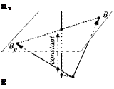
Let the unit normal vector of a plane be given by и (see Fig. 2.17). Premultiply­ing Eq. (2.23) by the transpose of и generates scalar products on both sides of the equation

US HR = uUSfjBa + vus vb„ + us B0R

Подпись: n u R

Because и is orthogonal to sub0 and svb„- the first two terms on the right-hand side

are zero; and, with sb„r being constant (see Fig. 2.17), we have the condition for В to sweep out the plane: usBR = const.

Definition: A plane, with unit normal direction u, is defined by the sweeping

point В, referred to point R, such that the scalar product of the two vectors is constant

Подпись: (2.24)usBR = const

In your pursuit of modeling planes, you may wonder which definition is appropriate for your situation. Here are the telltales: If the plane is given by points or embedded vectors, use Eq. (2.23), otherwise apply Eq. (2.24) with the unit normal vector.

Example 2.7 Angle Distance Measuring

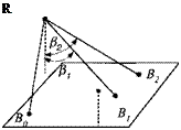
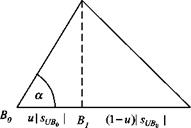
Problem. An aircraft R with an INS and distance-measuring equipment on­board is to determine the distances to points B and Вт, given its own known displacement vector sBoR (see Fig. 2.18). All three points lie on the surface with unit vertical vector u, established by the INS. The sensor of the distance-measuring equipment, however, can only measure the angles and fij between the local ver­tical and the direction to the points. Derive the equations that calculate the two distances sBir and |sB2*|.

Solution. Because all three points lie on the surface, we have from Eq. (2.24) the relationships

usBoR = usBlR = usBlR = const

The first term is given and establishes the value of the constant. The scalar product of the remaining terms can be expressed in terms of the length of the vectors and their angles from the vertical

|5BlS|cOs/Ji = |іВ2я| COS/S2 = const From which we obtain the desired lengths

Подпись: const const

Подпись: R

cos fa

r

Normal Form of a Plane

Fig. 2.19 Plane projection.

This is a typical application for the normal form of a plane. The unit vector of a plane is a free vector in accordance with the characteristics of a plane as a two-dimensional manifold. The free parallel displacement of the vector и in two dimensions corresponds to the two parameters и and v of the original definition, (Sec. 2.3.3).

Plane

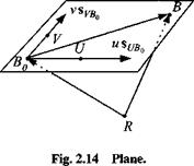
Whereas lines are one-dimensional, planes are two-dimensional manifolds. In Euclidean space we can safely speak about straight lines and flat planes, corrob­orating our experience. Our simulation may have to define such elements like ground planes, imaging planes, or target planes. Let us see how to model them in an invariant, coordinate-independent form (see Fig. 2.14).

Let the point В sweep over a whole plane, starting at Bq and maintaining R as the reference point. The movement over the plane is generated by two parameters u, є: —oo < и < +oo and v, є: —oo < v < +00 that modify the two directional vectors s ubq and s vb0 ■

Definition: A plane, subtended by sUBo and sVBr>, is defined by the sweeping

motion of the displacement vector of point В, referred to point R

sBR — US UB0 + vs VB0 + s B0R (2.23)

The plane is a two-dimensional manifold with parameters и and v.

The embedded vectors [л (/д01 and [sVHn ] stretch out the level of the plane. They do not have to be mutually orthogonal nor be unit vectors. We needed four extra points to describe the sweeping motion of B. The three points B0, U, and V establish the orientation of the plane, and R serves as reference point. If R should be in the plane, Bq could assume its function.

Example 2.6 Helicopter Landing Aid

Problem. Figure 2.15 shows a helicopter H preparing to land on an oddly shaped landing patch of a swaying ship. The pilot uses his landing aid, which displays his projection В on the landing surface, for touchdown near the center. This instrument has trackers that measure the three comers Bq, U, and V relative to the vehicle and provides them in geographic coordinates with the aid of an onboard INS. Develop the equations that are used to establish the orientation of the platform and the point В in geographic coordinates.

Solution. The platform is described by В sweeping out the plane just as Eq. (2.23) indicates

$bh = ms ub0 + vs Vb0 + s b0H

1G

Plane

Fig. 2.15 Helicopter landing patch.

where sBoh is measured directly and the other two vectors are obtained from the additional measurements suh and sVh

SUB0 = SUH + S HBa; s VBu = SVH + SfJBo

where sHBo — What remains to be determined are и and v. We can calculate

them with the help of the scalar product and trigonometry. Let us do it for u, and, by analogy, the solution for v follows. Referring to Fig. 2.16 and Eq. (2.15), we derive

ShB0SuB0 u pt/fio

cos a = і——- r-j—– г = – p—— p

SHB0 pr/flol sHBo

and solving for и

_ SflBpS un„

SUB0

H

Plane

Plane

Similarly,

Подпись: [^c/fio]0 = ISUH]G + [sr/Bo] ; [WBO] — [WH]0 + [jvffio] [■Sfitf]0 = u [ri/fi,, ] + + K«]

The problem was solved entirely in symbolic form. The processor of the instrument carries the calculations out in the same geographic coordinates that the measure­ments [іВон]с, lri///lG, and [sVH]G are given:

and the projection of the helicopter on the landing platform is calculated from or in the platform plane

[■Sfifio]0 — U’fitfl6 ~ [/fir,//]

Review briefly our two-step approach. We first derived the solution in vector form without reference to coordinate systems or their origins, followed by the coordinate form for programming. You can practice computing a sample numerical solution by solving Problem 2.2.

Straight Line

Straight lines arise as models of straight trajectories, star sightings, surveying of landmarks, or just a person walking down the aisle of an aircraft. They are considered of infinite length, but contain a displacement vector, whose endpoint moves along the line.

We let the point В slide along the straight line, starting from an initial point Bo, while maintaining R as a fixed reference point (see Fig. 2.12). The sliding process is generated by a scalar parameter и, e: — oo < и < +oo that lengthens or shortens the vector sBb0 ~ usUHt, on the line. The vector sub0 establishes the direction of the line and could be a vector of unit length.

Definition: A straight line, with direction sUB„ and anchored at sBoR, is defined

by the sliding of point B, referred to point R

Подпись: (2.22)Sbr = USuB0 + Sfl0«

The line is a one-dimensional manifold with parameter u.

Straight Line

It takes three extra points to describe the sliding of point В: the reference point R and the two points U and B0> which establish the direction of the line. If the reference point should be on the line, B0 could assume its function.

Straight Line

Fig. 2.13 Flight line.

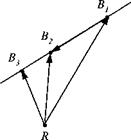
Example 2.5 Straight Line Trajectory

Problem. A surveillance radar R took two fixes of an incoming attack fighter: [ї]+к]с = [30 10 —8] and [лЙ2Й]с — [20 —5 —6] km (see Fig. 2.13). Timing the two fixes gave an elapsed time of At = 50 s.

1) Determine the average speed of the aircraft.

2) Where will the aircraft be ([5b^r]g) after Дт = 20 s has elapsed beyond Bj. assuming it continues its steady and straight flight?

Solution. 1) The speed of the aircraft V is calculated from the distance |.уЙ2Й| | divided by time

[^І7]С = [^f – [Si^f = [-Ю -15 2]

V = = — = 0.3628 km/s = 362.8 m/s

At 50

2) Because the aircraft flies along a straight line, its displacement after 20 s from the radar station is according to Eq. (2.22)

[■Sfi3«]G = + [sBi/f]

where Іл’й, й| ]G points in the direction of flight. The parameter и is calculated from the time ratios

At

then the radar will pick up the aircraft after 20 s at [Sb^]G = 1.4 x [-10 -15 2]+ [30 10 -8] = [16 -11 -5.2] km

The parameter и in this example is actually a time ratio, which occurs quite often in these types of problems.

Straight Line

Displacement of Points

Let us recap: The location of a point is meaningless unless it is referred to a reference point. So, for instance, the location of the center of mass (c. m.) of a missile В must be related to a tracking station, the launch point, or the target coor­dinates. The term displacement implies that mutual relationship. If the reference point is R, then the displacement vector of the missile is sbr. Its time dependency is expressed by sbrU). The displacement of a point is an invariant tensor concept, valid in any allowable coordinate system. For computational attainment this first – order tensor must be expressed in a coordinate system to be processed numerically. For instance, the missile may be measured in the tracking station coordinates ]я. Then the displacement vector’s coordinates are

‘іі(Г)"

S2(t)

Example 2.4 Helical Displacement

Problem. A missile makes an evasive circular maneuver toward a tracking radar R. Its closing speed is v, revolving at the angular velocity со on a helix of radius r. Suppose the Iя direction of the radar coordinate axes is parallel to the helix centerline. Formulate the displacement vector of the missile wrt to the radar in radar coordinates.

Solution. You should be able to verify the result with the help of Fig. 2.11.

—vt

r cos(wt) r sin(<uf)

For emphasis I point out that the coordinate axes are completely defined by di­rection and sense. They are free floating without origin. Drawing them from a common point, as I have done in Fig. 2.11, is convenient but unnecessary.

Displacement of Points

Fig. 2.11 Missile displacement.


Modeling of Geometry

As you build your aerospace vehicle simulations, you will be surprised at how much time you spend just getting the geometrical situation right. You have to keep track of vehicles in various coordinate systems. They may be moving along lines, and their proximity to certain planes may be of interest. Some of the vectors must be projected into new directions and others into planes. We may even have to deal with reflection and rotational symmetries.

Geometrical models will be with us throughout this book. In this section we build on the elements of tensor algebra and formulate such mundane things as lines, planes, and projections. Yet you will be surprised how different the invariant formulations are from the customary treatment.

Dyadic Product

The third possibility is the multiplication of vector x with the transpose of vector у to obtain tensor Z,

Подпись: (2.20)xy = Z

which represents, for any allowable coordinate sy stem ]A, the matrix multiplication

Подпись:

Dyadic Product

мАшА = [z]A

We borrowed the name dyadic product from vector mechanics, which avoids ten­sors by decomposing them into vector form and calling that hybrid construct a dyad. We have no need of dyads themselves, having committed ourselves to mod­eling flight mechanics by tensors only.

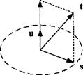
If both vectors x and у are one and the same unit vector u, then the dyadic product produces the projection tensor P. Given any vector t, its projection on the и direction is the vector r, resulting from

r = Pt with P —ий (2.21)

You can easily convince yourself of that fact by substituting the definition of P into Eq. (2.21) r = uUt and recognizing that the scalar product Ш gives the length

and и the direction of vector r. In any coordinate system, say ]A, the projection tensor has the form

u

UU2

U j М3

M2M1

uj

M2M3

M3M1

ИЗИ2

u

[P]A = [и]А[й]А =

It is a symmetric matrix because the scalar product of coordinates is commutative.

Example 2.3 Thrust Vector Projection

Problem. The direction of the centerline of a missile is given by the unit vector

[m]g = [0.2 0.3 —0.9327] in geographic coordinates. To make a course correc­tion, the gimbaled rocket motor turns the thrust vector away from the centerline to a position given by [f]G = [7.6 12.8 —36] kN. Determine the thrust vector along the centerline of the missile [r]G in geographic coordinates. (See Fig. 2.10.)

Solution. We just substitute the values of the example into Eq. (2.21) and calculate the centerline thrust vector

[r]G = McmG[t]G =

– 0.2 – 0.3

[0.2 0.3 -0.9327]

-7.6′

12.8

_

‘ 7.787 – 11.681

-0.9327

-36

-36.317

The matrix product can be executed any two ways. Either first calculate the pro­jection tensor and multiply it with the thrust vector, or evaluate the scalar product first and then multiply it with the unit vector. Both options lead to the same result.

Dyadic Product

We have come to the vista overlooking the foundations of mathematical model­ing of aerospace vehicles. Classical mechanics is the environment, and Cartesian tensors are the building blocks. We reviewed the axioms of mechanics as well as the Principle of Material Indifference and postulated the sufficiency of points and frames as modeling elements. Simple Cartesian tensors are our language with em­phasis on the invariant, coordinate-free formulation of physical phenomena. There are many more overlooks still ahead. However, we pause and apply our newfound skills to some important geometrical modeling tasks.

Vector Product

Let us ask another question: What kind of multiplication of two vectors x. у yields a vector z? From matrix algebra we know that a 3 x 1 vector is only obtained by the multiplication of a 3 x 3 matrix with a 3 x 1 vector

1Х][у] = И (2.16)

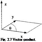
We want to explore the form of [X]. Vector algebra gives us three conditions for a vector product, as visualized by Fig. 2.7:

1) z normal to x and y.

2) |z| = area of x and у parallelogram.

3) right-handed sequence: x —> у —*■ z.

Подпись: Fig. 2.7 Vector product.

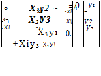
These conditions will lead to the conclusion that [X] is the skew-symmetric form of x 1:

■*f

A

‘ 0

-*3

X2~

MA =

*2

O [X]A =

*3

0

-X;

_*3_

_~*2

Xl

0.

for any allowable coordinate system ]A. Therefore, the vector product in tensor algebra is expressed by

Xy=z (2.17)

with the understanding that X is the skew-symmetric tensor of x.

Proof: If X is skew-symmetric, it satisfies the three conditions of the vector

product:

1) The first condition consists of two orthogonality conditions, a) For z to be normal to x, their scalar product must be zero: zx = 0; with Eq. (2.17) yXx — 0, which is satisfied if Xx = 0 . This is indeed the case as demonstrated by the matrix multiplication (for any ]A)

0 лгз — xf

A

~xf

A

X3X2 – X2X3′

A

-СГ

—хз 0 X

Xl

=

-X3XI +XIX3

=

0

X2 —X 0.

Хз.

X2X1 — XX2

0

Vector Product Vector Product

b) For z to be normal to y, their scalar product must be zero: zy = 0; with Eq. (2Al)yXy = 0, which is satisfied if X is skew-symmetric

The matrix multiplication holds for any allowable coordinate system. Therefore, if X is skew-symmetric, so is X, and the first condition is satisfied.

2) The second condition requires that the length of vector kl = area of the parallelogram subtended by the vectors* and y. Let us express Eq. (2.17), with X as a skew-symmetric matrix, in an arbitrary coordinate system ]A.

~Zl

A

– 0

-*3

X2

A

"Tf

A

■~*зУ2 + ТгУз-

Z2

=

*3

0

X

У2

=

*ЗУі – *іУз

.гз.

. x2

X

0.

-Уз.

_-*2Уі +Хіу2_

The scalar product of z with itself is the square of its absolute value [z}A[z]A = z2 = z + zl + z]

= (Х2уъ – ХЪу2)2 + (*ЗУі – ХіУз)2 + (хіУ2 – Х2у)2 = (х2 +х+ х|)(у2 + у + Уз) – (ХіУі + Х2У2 + *зУз)2 The last line can be written as

kl2 – w2|y|2 – ([X][y])2 = M2|y|2 – |x|2|y|2cos2в = |x|2|y|2(l – cos26») Replacing (1 — cos2 в) = sin2 в and taking the square root yields

kl = kllyl sin#

which is the area of the parallelogram between vectors x andy. By choosing for X the skew-symmetric form, we have indeed satisfied the second condition of vector multiplication.

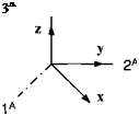
3) The third condition states the right handedness of the vector product. Let us introduce a right-handed Cartesian coordinate system Iа, 2A, and 3A. For the particular situation in Fig. 2.8, the vector product assumes the form

– 0

0

х2-

л

"0"

А

– о –

0

0

У2

0

–Х2

Хі

0_

0

_*1.У2_

[zf = [X]A[y]A

If x and у2 are positive, so is гз – Therefore, the skew-symmetric form of [X] satisfies the right-handedness condition as demonstrated by this specific example.

Подпись: 3A

We have indeed confirmed that the vector product of two vectors x and у consists of the multiplication of the skew-symmetric form of vector x with vector y. In coordinate form we execute a matrix multiplication.

I introduced vector multiplication in a simplified form, adhering to vector me­chanics rather than to tensor algebra. The right-handed convention eliminates the need for third-order tensors, which are really required to define the vector product properly. For the theoretically inclined among you, I provide the tensor definition of a vector product. Let, v,, and zk be three vectors in Euclidean space, and c, jk the third-order permutation tensor, then the vector product is defined (dummy indices summation implied):

Zi = SijkXjyk

It is valid for any type of coordinate system compatible with the Euclidean metric. By agreeing to use only right-handed Cartesian coordinate systems and the right – hand rule of vector products, we can use the simpler Eq. (2.17) as a definition of the vector product. You will see that this version is adequate for modeling all situations related to aerospace vehicles.

Example 2.2 Area Calculation

Problem. A farmer’s son inherits a rhombus-shaped field (Fig. 2.9). The bam is located on the corner B. With a global positioning system (GPS) set he records the coordinates of В and the two adjacent comers C and D. Then he converts the data to two vectors in geographic coordinates [,?celG = [0.5 2 0] and sdhg = [2 0.5 0] km. How many square kilometers of land did he inherit?

Solution. Apply Eq. (2.17) and take the absolute value of the cross product to obtain the area A:

A = |[SCB]Gto»]G|

where Schg is the skew-symmetric form of [s’cel0-

Г 0

0

2 –

– 2 –

‘ 0 "I

0

0

-0.5

0.5

0

L-2

0.5

0

0

-3.75J

Notice, there was no need for a coordinate system origin.

2.2.5.1 Vector triple product. For any three vectors x. y. andz with X and Y, the skew-symmetric forms of x andy, the vector triple product, is defined as

XYz = yxz — zxy (2.18)

which are to be interpreted as matrix multiplication

тти = мим-мим

The left-hand side involves two vector products [w] = [F][z] and X]w. The right-hand side is the subtraction of the vector M, multiplied by scalar HM from the vector [y], multiplied by scalar MM-

2.2.5.2 Scalar triple product. For any three vectors x, y, and z with X, the skew-symmetric form of x, the scalar triple product, is defined as

V = (xj)z=yXz (2.19)

implying the matrix multiplication

V = [ВДМ = ly][X№

V is the result of the scalar product of two vectors [w] = [Y][y] and [z] and equals the volume contained in the parallelepiped formed by де, у, and z.

Scalar Product

If the transpose of vector* is multiplied with the vector y, we obtain a scalar

Подпись: (2.13)xy = scalar

Подпись: [x]A[y]A = [xA x£ Scalar Product

This is the scalar product of matrix algebra. For any coordinate system ]A the scalar product is

If multiplied by itself, the resulting scalar is the square of the vector’s length. For any ]A

[x]A[x]A = (xf)2 + (xA)2 + (xA)2 = x2

Because the scalar |x[2 is invariant under coordinate transformations, this statement holds for all coordinate systems

** = |x|2 (2.14)

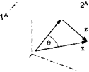
What is the form of the scalar of Eq. (2.13)? Consider the vector triangle of Fig. 2.6. From the law of cosines, the squares of the length of the three vectors are related by

z2 = {x2 + |y|2 – 2|x||y| cos#

On the other hand, z2 is also obtained from the scalar product of the vector subtraction z = x — у

z2 =zz = (x-y)(x – y)

= XX +yy – yx – xy

= x2 + |y|2 — 2xy

Scalar Product

Comparing the last equation with the law of cosines furnishes the value for the

scalar. The scalar product is therefore

= [jc||yicos6* (2.15)

The scalar is x times the projection of у on x and assumes the sign of cos в. In Eq. (2.15) we can exchange the symbols without changing the result; therefore

xy = yx

However, beware of moving the transpose sign. The result is xy Ф xy (why?).

Example 2.1 Angle Between Two Beams

Problem. A traffic control radar R tracks two aircraft A and В and records their displacements in geographic coordinates ]G as [їдя]° = [20 10 —9] and [srkg = [30 —20 —9] km. What is the angle between the two radar beams?

Solution. Solve Eq. (2.15) for в

Подпись:1‘SakII‘SBkI /

substitute the matrices and multiply out

( [20 10 —9][-lo] ^

Подпись: в — arccosУ202 + 102 + (-9)У302 + (-20)2 + (—9)2
Scalar Product

V

Tensor Algebra

To work with tensors, we need to know their properties of addition and multi­plication. With your a priori knowledge of vectors and matrices, there will be little new ground to cover. Basically, tensors are manipulated like vectors and matrices. We only need to spend some time discussing the vector and dyadic products that take on a different flavor.

First-order tensors (vectors) can be added and subtracted, abiding by the com­mutative rule

Sbc = sba + Sac = Sac + sba (2.10)

and the associative rule

(®вс + Sca) + sab — Sbc + (sca+ sab) (2.11)

However, I do not recommend the exchange of the terms on the right-hand side of Eq. (2.10), because it will upset the rule of contraction of subscripts. Notice in Eq. (2.11)1 arranged the order of the subscripts to form the null vector s BB, which is characterized by zero displacement. You can verify this fact by contraction of the subscripts.

Multiplication of a vector sBC with scalars a and fi is commutative, associative, and distributive:

Подпись: (2.12)ci(Psbc) = P(usBC) = (ccP)sbc (a + P)sBc = otsBc + Psbc

Next I will deal with the multiplication of two vectors. There are three pos­sibilities, distinguishable by the results. The outcome could be a scalar, vector, or tensor. Therefore, we call them scalar, vector, or dyadic products. The word dyadic is borrowed from vector mechanics, which calls stress and inertia tensors dyadics. I will use the symbols x and у for the two vectors, but also write them in the bracketed form [jc] and [ y|, to emphasize their column matrix property. If they do not carry a superscript to mark the coordinate system, they abide in any

allowable coordinate system and are therefore first-order tensor symbols just like x andy.

Cartesian Tensors

A first-order tensor (vector) x is the aggregate of ordered triples, any two of which satisfy the transformation law:

MB = [T]BA[xA (2.3)

where ]A and ]B are any allowable coordinate system.

A second-order tensor (tensor) X is the aggregate of ordered 9-tuples, any two of which satisfy the transformation law:

Щв = [T]BA[X|A[f]M (2.4)

where ]A and ]B are any allowable coordinate system.

By aggregate I mean the collection of all possible transformations among all allowable coordinate systems. That class could contain as many as oo2 elements: an infinite number for every frame over infinite numbers of frames.

How useful is this definition with infinite components? We can take two view­points:

1) Physical point of view—Tensors describe properties of intrinsic geometrical or physical objects, i. e., objects that do not depend on the form of presentation (coordinate system).

2) Mathematical point of view—Because tensors are the total aggregate of all ordered n-tuples, they are defined in all coordinate systems and thus are not tied to any particular one.

As we model aerospace systems, we deal with the physical world. Therefore, I adopt the physical point of view in this book and interpret these definitions in an intrinsic or invariant sense. The physical quantities exist a priori, with or without coordinates. The introduction of coordinates is just an expedience for numerical evaluation.

Cartesian Tensors

Fig. 2.2 Vector triangle.

A scalar is a particularly simple tensor. It remains the same in any allowable coordinate system, a useful characteristic that will serve us well in many proofs. We define a scalar as a physical quantity without any directional content, like mass, density, or pressure. Even particles and points belong in this category.

Some examples should clarify these definitions. Let us begin with the concept of a point and ask the question how do we determine its position? A point can have any position in space, or better, a point has no position unless related to another point, an intuitive postulate that follows from the Galilean relativity principle. The statement “I stand on the moon” uses the moon as reference. By just asserting “I stand,” nothing meaningful has been conveyed. Suppose I am modeled by point В and the footprint of Neil Armstrong is point A. Then my displacement from A is given by the vector s BA, and the displacement of the footprint with respect to me is sab – Both are related by sba = — sAb • Notice the important Rule 1: Subscript reversal changes the sign. If Michael Collins, at point C, wants to determine my position sbc and he knows the displacement of the footprint from him sac, and my displacement from the footprint sba, he can add the vectors to obtain the result (Fig. 2.2):

sbc = sba+sac (2.5)

Rule 2 becomes evident: Vector addition is by subscript contraction. The sub­scripts A are deleted to get the BC sequence

ВС <- В A+A C

contraction

Notice also the location of the arrowheads in Fig. 2.2. They are always at the first point of the subscript. The displacement of point В wrt point C is sвс with the arrowhead at point В.

To describe this scenario, there was no need to refer to any coordinate systems. We modeled the three entities by points and related them by invariant displacement vectors. For numerical evaluation, however, we have to choose coordinate systems. Suppose Collins wants to use a coordinate system ]c associated with his frame of reference. He expresses all terms in Eq. (2.5) by ]c coordinates

[SfidC = [Sba]C + t*Ac]C (2.6)

However, my displacement from the footprint is given in a coordinate system ]B, associated with my reference frame B. He therefore transforms my coordinates from ]B to ]c using the transformation matrix [T]CB according to Eq. (2.3):

Cartesian Tensors

– 2a

Fig. 2.3 Radius vector.

and substitutes the known coordinates into Eq. (2.6):

[Sficf = [T]Cfi[sBA]B + [sAC]c

If Collins knows the transformation matrix [ T]CB, he can compute my position in his coordinates.

Suppose his calculation furnishes [sic]c = [30,100 —1,500 2,800] km (I use the transposed to conserve space). To interpret the result, he has to know the direction and positive sense of the coordinate axes. If Iе is forward, 2C right, and 3C down, then the numbers would indicate to him that I am 30,100 km in front of him; 1,500 km to the left; and 2,800 km below. Please observe an important fact: no mention of a coordinate system origin was made. The numbers make perfect sense without Collins being at the origin. You may be shocked, but here is Rule 3: Coordinate systems have no origins.

Without origins, we have to dispose of radius vectors. They are used in vector mechanics to locate points in coordinate systems. But by doing so, the origins are made reference points. Because coordinate systems are purely mathematical entities, we cannot intermingle such physical reference points.

I will show that radius vectors are not vectors in the sense of the first-order tensor definition Eq. (2.3) and therefore cannot be part of our toolbox. Displacement vectors, on the other hand, are legitimate tensors.

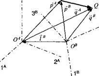
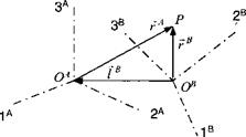
Figure 2.3 depicts the radius vector rA emanating from the origin Oa of the coordinate system A to the point P. Two radius vectors associated with two coor­dinate systems A and В are related by the vector addition rR =rA +lB, where lB is the radius vector of the origin 0A, referenced in the В coordinate system (see Fig. 2.4). With [TBA the transformation matrix of coordinates В wrt A, the radius vector rA in coordinate system A transforms to the radius vector rB in coordinate

Cartesian Tensors

3A P

Cartesian Tensors

Fig. 2.5 Displacement vector.

system B, as follows:

Kl

~hi

t2

hi

Гів1

4

=

hi

*22

*23

4

+

lB

l2

1— •ч

wCe

l_

-hi

*32

*33_

4

lB

L(3 J

and the abbreviated matrix notation

[rB]B = [T]BA[rAf + [if (2.7)

Compare this transformation with the transformation that defines a tensor Eq. (2.3). Because of the additional term [If, the radius vector rA does not transform into rB like a first-order tensor and therefore is not a tensor.

Conversely, let us prove that displacement vectors are tensors. Introduce the vector sqp as the displacement of point Q wrt point P, as shown in Fig. 2.5. It is related to the radius vector of coordinate system A by

[sQpf = [qAt ~ [pAf (2.8)

and to those of coordinate system В by

[sQpf = [qBf – [pBf (2.9)

The radius vectors [qBf and [pBf transform according to Eq. (2.7):

[qBf = [TfA[qAf + [If [pBf = [TfA[pAf + [If

Substituting these into Eq. (2.9) and with Eq. (2.8) yields

Indeed, the displacement vector Sqp transforms like a first-order tensor

[sQP]B = [T]ba[sqp]a

and therefore is a tensor.

I hope that you appreciate now the difference between radius and displacement vectors. Because we want to use only invariant tensor concepts, I have to give Rule 4: Radius vectors are not used. Before we move on to geometrical applications, let us summarize the four rules.

Rule 1: Subscript reversal of displacement vectors changes their sign.

Rule 2: Vector addition of displacement vectors must be consistent with sub­

script contraction.

Rule 3: Coordinate systems have no origins.

Rule 4: Radius vectors are not used.