Our heavyweight helicopter equal in the world does not have
In Rostov started production of the most load-lifting rotary-wing car The Russian holding «Helicopt[...]

Everything about aircrafts and helicopters. News and events in aviation worldwide. Civil, transportation, military helicopters and airplanes.

Everything about aircrafts and helicopters. News and events in aviation worldwide. Civil, transportation, military helicopters and airplanes.

Everything about aircrafts and helicopters. News and events in aviation worldwide. Civil, transportation, military helicopters and airplanes.

Everything about aircrafts and helicopters. News and events in aviation worldwide. Civil, transportation, military helicopters and airplanes.


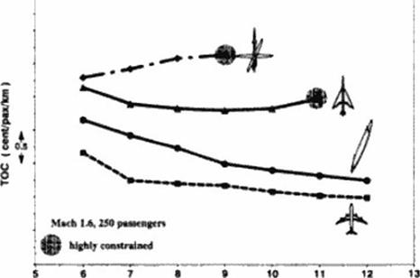
The aerodynamic and structural benefits of the oblique flying wing translate directly into better aircraft operating economy.
The oblique flying wing was directly compared with conventional supersonic and subsonic transports based on operating economy for a range of missions with specified performance and environmental constraints. All aircraft were evaluated with the same analysis routines and to the same level of structural, aerodynamic and propulsion technology comparable of that achieved by the new generation of subsonic transports. In terms of direct operating costs, oblique flying wings with more than 400 passengers were superior to conventional wing-body configurations over the entire Mach 0.8 to Mach 2.0 operating range The improvement was smaller than the uncertainty of the analysis at Mach 0.8. but more than a factor of two at supersonic speeds up to Mach 2.0. Unlike conventional delta wing transports it will be possible to design oblique flying wings for payloads up to 600 passengers and ranges up to 12000 km (6700nm) while satisfying current economic, performance and environmental requirements.
Table 6 compares a 400 passenger OFW and a 747*400.
|
OFW |
В 747-400 |
|
|
Cruise speed |
M 1.6 |
M 0.85 |
|
Range |
9000 km |
10300 km |
|
Geometry: |
||
|
Wing Area |
1316 |
511 |
|
cabin 1 x w (m) |
39.2 x 7.5 |
57×6.1 |
|
total 1 x w (m) |
120 x 14.5 |
69×60 |
|
Weights |
||
|
OE (kg) |
127000 |
180000 |
|
MTO(kg) |
30700 |
385000 |
|
SLS Thrust (kN) |
4×230 |
4×250 |
|
Price (1994) |
285 MS |
140 MS |
|
Production (scat. km. year) |
3.0 x 10⁹ |
1.8 x 10⁹ |
|
Est. Total Operating costs |
9 Set / pax. nm |
9 Set /pax. nm |
|
Table 6 Comparison of an OFW with a 747-400 |
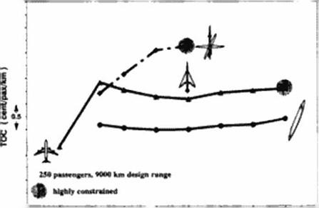
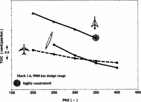
Figure 137 to Figure 139 compare the total operating cost of optimized oblique flying wings with other optimized aircraft configurations.
|
![]() Comparison of TOC’s as a Function of Range
Comparison of TOC’s as a Function of Range
|
|
Figure 139 Comparison of TOC’s as a Function of Size |
A cknowiedgcmtn is
The author would like to thank all his cotlegues at Stanford. NASA Ames and Daimler-Benz Aerospace Airbus who contributed to this project, especially Herbcn Sadowski for his work on the layout and the drawings and Dr. Steve Morris for his contributions to the stability and control part of this paper.
19.9 Conclusion
This paper shows that the oblique flying wing is a technologically and economically feasible transport.
The effect on ozone depletion by supersonic transports is still a hotly debated issue. But most scientists accept that ozone depletion by nitrous oxides is caused by the following mechanisms in order of importance.
• Cruise altitude. For a given rate of N0^ injection into the atmosphere the rate of ozone depletion will go up nearly linearly with altitude from altitudes between 15 and 20 km.
• Combustor entry conditions. The higher the combustor entry temperature and pressure the higher the formation of N0^.
• Fuel Efficiency. The higher the fuel consumption the higher the formation of NOg.
Though the lower wing loading contributes to a higher cruise altitude, this effect is almost completely offset by the reduction in parasite drag. The reduced parasite drag will lead to a lower cmise lift coefficient and therefore a lower cruise altitude. Because the effect of fuel efficiency is less important than lowering the combustor entry conditions, the power plant effi* cicncy will be penalized by very strict ozone depletion standards After all elements were taken into account we did not find a significant difference in the ozone depiction of conventional wing-body aircraft and the oblique flying wing when the same cruise Mach number was considered. The effect OFW’s improved fuel efficiency was canceled by its somewhat increased flight altitude. According to the Chang model, the impact of a fleet of Mach 1.6 OFW’s replacing the current fleet of B747’s on the ozone layer will be less than the 2.5 reduction of the ozone column proposed by NASA. This is about one fourth of the impact of Mach 2.4 conventional transport and ten times the impact of the current subsonic fleet.
Sonic boom cannot he avoided. However current large supersonic delta wing type designs produce sonic booms in excess of 2.5 psf. much more than Concorde. On top of that the subsonic specific range of these aircraft is less than the supersonic cruise specific range. Flying subsonic over land will therefore result in a significant range penally.
The sonic boom of an oblique dying wing is much less than Concorde’s. It was determined using the Whitham F-function method and the TranAir full potential code. The OFW was modeled by a slewed elliptic lift and Sears-Haack area distribution, a panel method and a high definition surface geometry. All representations gave similar boom signatures, as follows: •
19.7.1 Noise
Strictly enforced noise regulations make the introduction of a long range supersonic delta wing type configuration almost impossible. The reason for this can be ‘easily’ understood.
Since the noise produced depends on the aircraft thrust, and since the thrust has to be balanced by the drag, higher drag means more thrust and thus more noise at a given airspeed. The large supersonic delta wing aircraft designs have take-off weights that arc comparable to those of the 747 and strive for the same take off field lengths. Unfortunately their wing spans arc typically only 60 b of the 747’s in order to make the wing longer for the same wing area. This reduced span more than doubles drag at the same flight speed.
If wc look at the equation for induced drag in the acrodynmics section wc sec that the designer can also increase the takeoff speed to lower the induced drag Higher takeoff speeds at the same thrust increase the takeoff field length and reduce the climbout distance to the noise flyover point. The designer may thus satisfy the sideline noise regulations, but not the flyover regulations or the field length constraints. If the designer decides to increase the thrust, the will reach rotation sooner and will climb out higher. Now he satisfies the flyover regulations, but not the sideline regulations.
So for an aircraft of the same weight and less span we need an engine that makes less noise at a given thrust. This can only be achieved by increasing the massflow through the engine Therefore a long range supersonic delta wing type configuration will have to be fitted with engines that base a much greater crosssection that B747 engines at takeoff. These
extremely wide engines also have to be very long because of the supersonic compression process. These very large engines cannot be spaced to close together because then they will start sucking in each others air. Even though they cannot be spaced to close together, they will have to be titled on a much smaller span. On top of all of this such large masstlow engines can double the weight and drag of the nacelles and limit the takcofT rotation angle.
The author sees no solution to the noise problem for large delta wing supersonic aircraft at this tunc. However, the oblique (lying wing is not caught in this catch 22 of noise and performance.
The high subsonic hft-to-drag ratio of the OFW allows the bypass engine to be throttled back to about 50 % of its available thrust while still maintaining the required airfield performance. Such a throttled back engine can meet the FAR36 stage 3 noise requirements without significant noise abatement measures. Future noise regulations will be met with similar penalties as those experienced by competing subsonic transports.
In the summer of 1987. Steve Moms flew an unpowered model of an unswept flying wing with such an artificial stability augmentation system. The model was dynamically stabile with a center of gravity at 32*fr of the mean aerodynamic chord. In 1990 Dr. Moms built and flew a 10 ft span powered oblique flying wing that was naturally stable. This aircraft was flown at sweep angles up to 60 degrees.
|
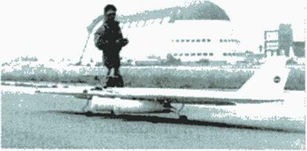
After these initial successes. NASA Ames awarded a $ 250.000 two-year grant to build a 20 ft, two engined oblique wing demonstrator. Even though its w ingspan almost matches that of a Cessna 152. the model OFW is still relatively small compared to the 400 ft full scale aircraft. This model is shown in Figure 132; the layout of the model is shown in Figure 133. Its
![]()
![]()
![]() flight stability is determined by the quantities i =
flight stability is determined by the quantities i =
![]() pi/
pi/
 |
odynamic force and moment derivatives.
• Тею 5MP ducted fan angina*
• ![]()
 |
 |
Onboard computer and eeneore to
I.-„-. t, . M| ОДО———— г mi-^i – л —» _
іііірОїТівш »wCvfvl ПіуПі Oflll
Figure 133 Layout of the Twenty Foot Oblique Flying Wing Model (Courtesy S. Morris)
Both the full-size aircraft and the model have (lie same values of these parameters at takeoff. The aerodynamic derivatives are worse for the model because of Reynolds number effects. Figure 134 shows the calculated OFW off-design performance with stability augmentation in place.
 |
Swaap Vanes 35° to 55*
Closed-Loop w/Ttxad gains
The model, as designed, relied on simplified control laws that used only 6 fixed gains and made the assumption that pitch and yaw were decoupled. The current model aircraft is stable up to 50" at which point it becomes spirally unstable. The spiral instability could be controlled by a different control algorithm that adjusts the gain for different sweep angles.
Unfortunately, the designers of the model were hampered by lower than expected servo performance. Reliable servo performance could only be guaranteed at 3 Hz. The severely reduced servo bandwidth (10Н/ specification) allowed the model to be only flown 2 % unstable rather than the planned 7 %. Allowing for the performance deficit of the servos the model flew as predicted on May 10 1994 as shown in Figure 135. According to the report (400) : M The flight began w ith a 23 s take-off roll where the aircraft accelerated to 45 mph TAS and then lifted from the ground after the pilot rotated the airplane with a pitch-up command… The model then climbed to an altitude of 150 ft and proceeded to enter a left hand pattern During this pattern the model was flown at speeds as low as 25 mph and as high as 65 mph with wing sweep commanded to hold 35° . During the second left pattern the wing sweep was increased to 50° for a few seconds and then returned to 35° (as shown in Figure 136). At the end of the second pattern… the landing pattern was easily executed and the model landed safely on the runway centerline direcly in front of the the video cameras and the flight data was retrieved. The pilot commented that the airplane flew more easily than the 10 ft. model which had no on-board computer.
|
|
|
Sweep (<[11]9) |
19.6.1 Concept
A control system consisting of a narrow trailing edge Пар and ai least one vertical fin can provide sufficient control authority to tnm the aircraft at the 32 $ chord design center of gravity in both supersonic cruise and takeoff and landing. Only a very small (typically 3 $) aerodynamic center shift was observed going from subsonic to supersonic speeds.
Stability and control in pitch and roll is provided by a 10$ multi segmented trailing edge flap, segmenting this flap increases the system reliability and enables roll control, each flap segment can be independently controlled by the on board flight computers. This flap system will put (he neutral point as far back as 37$ of the mean aerodynamic chord at OEW (operating empty weight), and smooth out any gust peaks.
The artificial stability and control system that controls this flap may use a standard feedback controller. This controller relates the aircraft altitude and altitude rate of change to an optimum flap deflection.
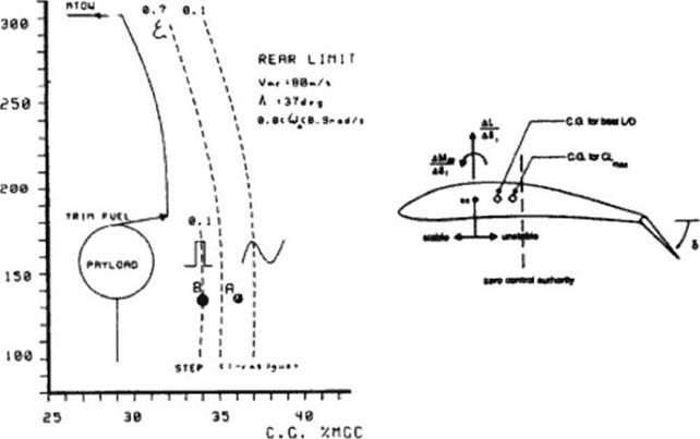
Figure 129 shows the predicted rearward stability limits when such a feedback system is in place. (The dynamic model used in this work was only quasi-3d and accounted for aerodynamic lag.) The dynamic stability limit is set by a 20.13 m/s (66ft/s) gust at minimum control speed. As can be seen, the system is more sensitive to step gusts than to an FAR25 (1-cosine) gust. The rearmost center of gravity position is located in front of the step gust’s neutral point.
flRSS
c I. I*» >
|
Figure 129 Rearward Stability Limits |
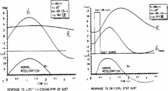
The stability limit moves forward with increased configuration weight because the flap deflection required to balance the aircraft will cause the flap ю stall for limit gusts in low speed flight. Typical aircraft responses for center of gravity positions close to the neutral point arc depicted in Figure 130 (A and В refer to conditions in Figure 129 ).
|
Figure 130 Step and Cosine Gust Response |
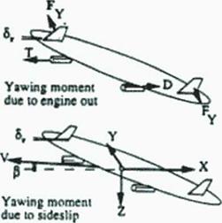
The configuration has at least one “all-flying" vertical tin. The combined size of the vertical tailplancs is set by the two engine out condition at takeoff. As shown in Figure 131, both vertical tailplancs are deflected to oppose the yawing moment caused by the inoperative engine. Crosswind landings can be performed without a bank angle. The vertical tailplanes and engines arc turned in the direction of the sideslip to eliminate the side force created by the sideslip angle For sideways maneuvering the inboard front and rear vertical tail should be loaded equally to balance the configuration around the /-axis. The present configuration can manage with Cy’s up
to ЬЧс of C{ by vertical tail deflection alone. Even more side force can be generated by banking
the wing.
Figure 131 also shows the required control deflections to counter a vertical gust. An upward vertical gust increases the angle of attack which in turn causes increased leading edge suction and side force. The side force can be compensated by symmetric vertical tail deflection
It is not just the aerodynamics that give the oblique flying wing an advantage over more conventional aircraft.
The location of aircraft components and the selection of the flight path and sweep can be done in such a fashion that the benefits of span loading can be achieved. Specifically, the following considerations have to be taken into account:
• Span loading All mass and load items arc distributed in such a way over the span that the structural bending loads are minimized. The embedded fuselage shells provide additional bending stiffness in the middle of the configuration Figure 128 shows the smeared equivalent skin box thickness distribution over the half span of the oblique flying w ing. Thus, span loading allows for an almost constant required skin thickness of 7mm allowing for efficient manufacturing
• Runway loads. The loads experienced during taxi and landing can be reduced by a two-legged main landing gear supported by a two auxiliary aft gears Such a layout also provides stable maneuvering during taxi. To allow the oblique flying wings to grow to the span required for efficient supersonic flight (120m) the gear legs have to be at least 40 to 50 meters apart. In order not to exceed the runway width such a gear span can only be achieved by sweeping
the wing to 45°.
• Gust loads. To reduce the gusts loads during climb the operation of the aircraft is restricted to lower equivalent airspeed than typical transonic transports. In addition the wing will have
to be swept to 50" to reduce the high lift gradients that cause high gust loads and to improve ride quality further.
Operation of the oblique flying wing in this fashion will increase the runway length and increase drag but not to the extent that this outweighs the structural advantages created by them. The advantages created by load minimization and span loading account for at least half the total economic benefits that are cited.
 |
from the application of composites materials then current subsonic aircraf t because of the higher productivity per pound of structural weight for a supersonic aircraft. However, in the case of the OFW their use is not required. Industry experience shows that intermediate carbonfibcrs with В MI resins achieve strain levels in excess of 0.5 % can result weight savings over conventional primary structures in excess of 25 $. The airframe life was specified to be over 75.000 hours with 50,000 supersonic flying hours and 25,000 pressure cycles A minimum skin thickness of 2 mm was specified to minimize foreign object damage.
Because the oblique (lying wing can adjust its sweep angle for each Mach number, it achieves higher lift-to-drag ratios than conventional configurations up to Mach 2.0. A conceptually good way of looking at this is presented by:
Dr., = Friction + + 1МІ (108)
I**2 q2nx] nX2
The first term in this expression. Friction, can be assumed constant. The second term is the induced drag. L represents the lift, q the dynamic pressure and b the aircraft span. The larger the span the less the induced drag for a given lift. The third term is the wave drag due to lift. M is the Mach number and X] represents the (weighted) average characteristic length of the aircraft’s pressure signal. For low supersonic Mach numbers the lengths Xj and X2 arc close to the
projected length of the configuration in the direction of flight. V in the third term represents the volume of the configuration. So the reduce the wave drag it is necessary to have a very long aircraft.
Since we need both a great span and a great length to minimize the drag of a configuration it makes sense to consider a variable diagonal distnbuton of volume and lift. Because the sweep is variable such a configuration can minimize drag for any Mach number.
Thick supercritical sections arc a key technology for the oblique flying wing. Sections as thick as 19 % will enhance the utilization of the wing volume reduce of structural weight.
|
Figure 122 shows the example resulting from (he author’s direct wing design method as described in chapter 16. see the OFW case study there (Figure 93). In view of the limitations of the artificial stability and control system the wing was trimmed around 32% of the chord. The wing is naturally stable in front of this location.
|
Tltc global design (wing area, thickness, aspect ratio etc.) was optimized for minimum total operating cost (406) The detailed design originated out of the optimization of the shape for minimum drag at cruise without moments around the center of gravity. Additional constraints were imposed to fit the payload according to the standard previously discussed. The design clearly shows the wing parabolic dihedral (bend) proposed by R. T. Jones. A bent oblique wing creates a linear twist distribution which compensates for the loading up of the aft w ing due to induced effects.
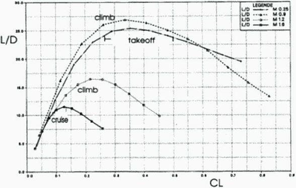
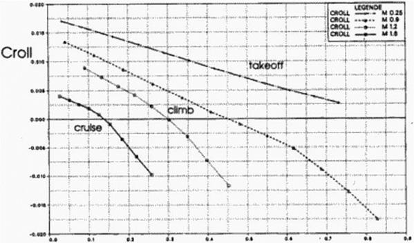
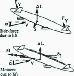
Figure 123 – Figure 127 show the aerodynamic forces and moments during flight for the full scale transport using this optimized shape. Notice that the aircraft flies only in very narrow corridors of angles of attack. The lift-to-drag ratios arc in excess of 25 at subsonic speeds and in excess of 11 at supersonic speeds. The pitching and rolling moments cannot be decoupled: if one analyzes the moments involved, it turns out (hat the neutral point moves along the center of gravity line. This is caused by the upwash induced from the forward w ing on the aft wing. For symmetric swept aircraft this phenomenon only causes increased pitching moments, but for oblique w ings this causes rolling moments.
 |
ALPHA
|
|
 |
|
Figure 126 Lift Coefficient Versus Rolling Moment Coefficient |
|
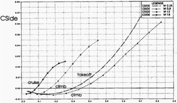
Figure 127 Lift Coefficient Versus Side Force Coefficient |
So, in a sense, the aircraft is close to neutrally stable about the long axis Under normal flight conditions there is no side force on the aircraft; at higher angles of attack, the leading edge suction produces a side force to the right.
The oblique wing designed with this new method had drag levels comparable to the theoretical minimum drag for oblique w ings of the same volume, lift and length. The estimates of oblique wing theoretical minimum drag by Jones and Smith [4011 arc therefore applicable to more realistic trimmed configurations.
Figure 118 shows the present baseline Daimler Benz Aerospace Airbus Oblique Flying Wing layout designed for 250 passengers and a 5000nm range at a cruise Mach number of 1.6. The passengers are accommodated inside cylindrical hulls inside the constant chord center section. All oblique flying wings considered in this work have the same chord of about 15 m. At this chord the 19 % thick airfoil can hold two five-abreast hulls. The interior layout conforms to the A320 standard: its center aisle is 2.20 m high and the doors are 1.95 m high. Since passengers are accelerated sideways during takeoff, shoulder straps w ill be required. Other layouts in which passengers will not be accelerated sideways during takeoff and landing arc optional. Entrance doors are placed in the nose of the aircraft. The emergency exits are found in the nose and trailing edge side of the passengers cabin, and can be reached by access ramps that lead to the top of the wing.
The pressurized hulls are laid along the spanwise direction and carry structural loads. The floor structure has a 50 cm crash zone. Figure 118 shows the cabin cross-section at the wing’s zero incidence. The cabin is lilted with respect to the zero incidence so that the range of floor incidences never vanes more than 3° from a level floor. The cargo is next to the passenger cabin, rather than under the floor, and offers space to containers up to 1.70m, so standard A340 LD3 containers can be fit.
Another deviation from the wide-body standard is the cockpit. Space is provided in the nose of the cabin to house two pilots. The pilot will have good visibility dunng approach and climb. His field of vision is 20° left. 90° nght at takeoff and landing, similar to the со pilots view in FAR 25.777. The oblique wing is swept with the left tip forward so the pilots have an unobstructed right view This is important with respect to the current air traffic nght-of-way rules.
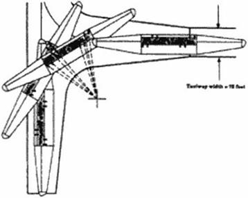
Figure 118 also shows the gear layout. The undercarriage has up to four main legs depending on maximum takeoff weight. The main landing gear is in the nose. A smaller gear is aft of the cabin. The best gear location is typically at 35% of the span for minimum structural weight. A constraint of 35 meters has been placed on the gear track so the aircraft can operate on runways of 50 m width. Figure 119 shows that it is necessary to have main gear steering to execute a turn. Takeoffs and landings are executed by rotation around the long aircraft axis. Apart from this unusual selection of the axis, the takeoff run is similar to that for a DC-3.
|
|
Figure 119 Runway Turn, Ref. (407)
Four fuel tanks are distributed over the span to reduce the structural loads during taxiing. To minimize trim drag, the center of gravity position can be moved by a fuel trim system as the case with all Airbus aircraft.
The nacelle» arc distributed along the span The ihrusl-vcetoring nacelle design shown in Figure I IS has the inlet almost parallel to the leading edge. It is comparable to the Olympus nacelle turned 90° around its long axis. At cruise the airflow is not turned, but at takeoff the inlet sucks in air from the nght – just as Concorde at a high angle of attack sucks in the air from below the aircraft -. Inlet bypass doors prevent the air from separating in the nozzle. The nozzle
then vectors the thrust to propel the aircraft at the takeoff sweep of 45°,
In view of the limitations of the artificial stability and control system the nacelles arc placed as far forward as possible; synergistic, cabin noise and aerodynamic considerations dictate their placement outside the passenger cabin. Engine core or fan bursts do not cause damage to the pressure hull, therefore greatly reducing the critical risk of sudden decompression above 13000 m. To increase engine-out yaw control and to minimize the wave drag and wing stress, the engines were podded in four nacelles. The engines are of conventional turbofan design with a low bypass ratio. Such an engine placement would not lead to any significant additional drag (3 counts) for Mach numbers between 1.4 and 1.8.
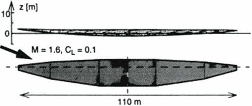
This baseline configuration avoids one of the classical objections against the flying wing, namely that it docs not have stretch potential, is not true for our baseline configuration. We can simply add center cabin sections of the wing’s maximum thickness. It can be easily shown that this will even increase the L/D of the configuration. Although the OFW is very long in comparison to other aircraft. Figure 120 shows that it can fit a realistic airport slot. The current designs fit a Very Large Transport slot sized at 80 m x 80 m.
|
|
 |
To give the reader an idea of what an oblique flying wing is. we will start w ith a description the baseline design and layout.
Next we will focus on the main advantages of the configuration: Lower drag due to the variable sweep oblique wing and lower weight due to spanloading. It is the combination of both effects that make the oblique (lying wing an economical long range supersonic transport
Л big concern for a new type of configuration is the question whether it can fly safely. In the third part we will therefore discuss the issues that relate to safe flight, controllability and stability. In particular we will discuss the results of the 1994 flight tests at NASA Ames.
In the 1970’s the unacceptable environmental impact of supersonic transports, especially noise and ozone depletion were the cause of the cancellation of the USA SST program So in the last part of this paper we will assess the oblique flying wings environmental performance.