Category Principles of Helicopter Aerodynamics Second Edition

Chapter Review

This chapter has summarized the various computational methods being used in the analysis of helicopter problems. The important role of computational fluid dynamics, particularly in the form of the Navier-Stokes equations, in better understanding problems in helicopter aerodynamics has been emphasized. To some, the use of “CFD” is held out to be the salvation for the helicopter aerodynamicist, but this is a misleading perspective. CFD will ultimately prevail for the complete simulation of the flow about a helicopter, but there are still many fundamental numerical and practical issues to be resolved, least of all is in the proper and efficient coupling of the CFD to the dynamic and elastic structural motion of the various components of the helicopter. The preservation of vorticity over many rotor revolutions is clearly one key to providing better CFD models of the rotor wake. The development of more general and more adaptable turbulence closure models must also continue, particularly as they apply to describing the vortical nature of rotor wakes and the structure of the blade tip vortices. Such issues are important in better understanding a whole host of practical helicopter flight problems such as descending flight, maneuvers, flight in the VRS or in autorotation, interactional aerodynamics between various airframe components, flight near the ground and many problems in rotor vibration and acoustics. Meantime, these problems require immediate or shorter term solution capabilities, and it is unrealistic to expect these problems to wait in the sidelines until pure CFD reaches the required level of maturity. Meantime, more parsimonious aerodynamic models must continue to be developed, with the ideal of fusing together the capabilities of the best available models.

It is fair to say that the large computer resources required, and the algorithmic challenges posed by modem CFD methods have thus far limited their use for many practical problems in helicopter design. This is especially the case for the Navier-Stokes and Euler-based methods. The community has invested heavily in a variety of CFD approaches, but the task of modeling the flow about a complete helicopter, or even just the rotor, is indeed truly

daunting. The various rotating and nonrotating aerodynamic components of a helicopter make generating appropriate grids on which to solve the equations a challenging problem in itself. Passing flow information back and forth between these grids requires special numerical algorithms and incurs significant computational cost. Until the grid generation process becomes more automated and can tackle complex geometries with ease, the use of many types of CFD methods will not lie in the domain of practicality for helicopter designers. Even then, validation of the models and resulting flow predictions requires extensive work and continues to offer challenges for the experimentalists in providing suitable quality surface and off-surface flow field measurements. Unless proper validation of its predictive capabilities can beensured, CFD cannot be assigned the confidence levels necessary for use in design, no matter how fundamentally sophisticated the method. These problems offer many new opportunities that are rich for new research.

There are other areas such as aeroelasticity and flight mechanics simulations, where the coupling of CFD into the solution process is less practical, at least in the shorter time. This is in part because of high computational costs and/or the difficulties in coupling different types of solution methodologies. How the helicopter actually flies comes under the domain of flight mechanics, and flight dynamics and handling qualities assessments may require a real-time or near real-time solution, rendering many “state-of-the-art” aerodynamic models impractical. Also, for some applications the equations describing the aerodynamics must be written in a specific mathematical form (as ordinary differential equations, for instance) to be compatible with the methods of analysis used for flight control system design. This is where the role of so-called “reduced-order” models can make significant inroads by avoiding the expense and difficulties of a complete CFD solution, yet much validation is required to gain confidence levels. The proper coupling and integration of aerodynamic methods of analysis into other disciplines of helicopter analysis is really the key to designing better helicopters. It is clear that the future offers many exciting opportunities for research focused toward the development of more innovative computational models with greater predictive capabilities. Only then can the problems that limit the performance and capabilities of the helicopter be understood and mitigated. Given the complexity of the helicopter flow field, it is likely that CFD methods for helicopter applications will reach maturity only long after their application within the fixed-wing community is accepted as standard practice.

[1] A branch of mechanics that deals with the motion of air and the effects on bodies.

[2] Understanding the basic aerodynamics of vertical flight. The theoretical power required to produce a fixed amount of lift was an unknown quantity to the earliest experimenters, who were guided more by intuition than by science. The first sig­nificant application of aerodynamic theory to helicopter rotors came about in the early 1920s. [See also Liberatore (1998) for a historical discussion of this point.]

[3] The lack of a suitable engine. This was a problem that was not to be overcome until the beginning of the twentieth century through the development of practical internal combustion (gasoline-powered) engines. The steam engine was never a viable concept for any type of aircraft. However, the development of internal

[4] A braccia is an old Florentine unit of measure, approximately equal to one arm’s length, although it has been defined variously between 15 and 39 in (0.28 to 1 m).

[5] Newton’s third law states that for every action (force) there is an equal and opposite reaction (force).

[6] In 1897, a British patent was to be granted to White (1898) for a vertically lifting machine with variable pitch (feathering) blades, but it was a windmill concept by Lewis & Lewis (1838) that probably saw the first use of a swashplate for blade pitch control on a rotating-wing.

[7] In addition, the content of the entire first issue of the Journal of the American Helicopter Soc., 1(1), Jan. 1956, was devoted to the early autogiro and helicopter developments in the United States.

[8] Of interest is the rotary engine built by Berliner in 1905, which predates the Le Rhone engine, and this

was built also with the specific purpose of installing it in a helicopter.

[9] The ability to autorotate is really a distinguishing feature of a successful and practical helicopter.

[10] This phenomenon is called blade vortex interaction or ВVI – see Chapters 8, 10, and 14.

[11] Meaning the slipstream is well downstream of the rotor at infinity or in the vena contracta, although in practice this may only be less than one rotor radius.

[12] From a piloting perspective the decrease in power requirements for flight found when moving from hover cause an excess power available and so the helicopter will climb. Pilots often call this climbing behavior “translational lift,” but the term is a misnomer because unless significant acceleration is involved, rotor lift equals helicopter weight and the helicopter climbs by virtue of the excess power available not from excess lift generation.

[13] Typically, a minimum of 20 elements must be used to ensure an adequate numerical resolution of the

inflow and spanwise loading, but 40 elements or more is desirable.

followed by a momentum balance using the conservation laws in integral form. This, however, is a technique valid only below stall where there are no viscous losses from rotation of the fluid (see Section 7.8 and Question 7.9).

[16] Measurements of 2-D section drag are often made by measuring the velocity in the wake of the airfoil,

[17] Normally in aerodynamics we use lower case subscripts to denote sectional values and subscripts in capitals to mean total or integrated quantities.

[18] Collective pitch: This input (6q) increases the main rotor blade pitch angles by the same amount, and, therefore, this changes the magnitude of the rotor thrust. The collective is changed by a lever that is held in the pilot’s left hand, with an upward pulling motion required for an increase in thrust. Increasing collective pitch also requires an increase in power. On some helicopters this requires the pilot to open the throttle (increasing fuel flow to the engine), which is operated by a twist-grip at the end of the collective lever. However, on most helicopters the fuel-flow is controlled by an engine governor, which automatically maintains rotor rpm at the regulated value as rotor torque required increases or decreases.

[19] Lateral and longitudinal cyclic pitch: These inputs impart a once-per-revolution cyclic pitch change to the blades. Lateral cyclic {0c) is applied such that the rotor disk can be tilted left and right. This changes the orientation of the rotor-thrust

[20] On tandems such as the CH-46 or CH-47 the rear rotor is placed substantially higher than the front rotor to minimize these interference effects.

[21] To a first approximation this can be assumed to be a fixed fraction of the main rotor power.

[22] 1 W3/2

R =——– —=——— . (6.53)

FM *j2jtp Pavail

Assuming a net aircraft and pilot weight of 200 lb (optimistic) and a rotor a figure of merit of 0.75 (also optimistic, even with the benefits of ground effect) operated at sea level conditions, then solving for the rotor radius gives more than 77 ft. It is probably unrealistic to build such a large single rotor with blades that are both lightweight and have sufficient strength and structural rigidity, although the attempt has been made. Multirotor machines may offer better prospects in this regard. Furthermore, because such a rotor will have blades that turn at a low rpm, the tip Reynolds numbers will be low and the viscous drag on the blades will be relatively high. It would seem unlikely, therefore, that such a rotor with a FM of 0.75 is realizable. However, it is interesting that if it were possible, such a rotor would have a disk loading of only 0.0107 lb/ft2 and an average induced velocity, Vh, of about 3 ft/s.

Filippone (2002) considers the possibility of two or more crew to power a HPH because this wilFdouble the effective power available. This is a variation of the engine selection problem previously introduced in Section 5.5.5. Yet because the crew weight will at least double, Eq. 6.53 shows that that the rotor radius will have to increase by at least a factor of 1.41 to maintain a low disk loading, and so empty airframe will also increase (i. e., an increase of the empty weight fraction.) This is a direct result of the square-cube law (see Section 6.4.1). The various trades, however, require further study for multirotor HPH configurations.

Any HPH must have a large diameter rotor operating in close proximity to the ground, so the issue of ground effect (see Section 5.8) on rotor performance must be carefully

[24] A high maximum lift coefficient, Qmax. This will allow a rotor with lower solidity and lighter weight, or will permit flight at higher rotor thrusts and under higher maneuver load factors.

[25] A high drag divergence Mach number. This will permit flight at high forward speeds without prohibitive power loss or increase in noise levels.

[26] The SC1095-R8 has a modified nose shape and a slightly smaller thickness-to-chord ratio than the SC 1095. For this reason, it is sometimes referred to as the SC1094-R8 – see Flemming (1982).

[27] This is called “dynamic stall” and is discussed in detail in Chapter 9.

[28] Notice that this case does not represent an oscillating airfoil in AoA because the pitch-rate terms are not included.

[29] The apparent mass contributions to the forces and pitching moments, which are proportional to the instantaneous motion, are often included as part of the quasi-steady result. If they are not, then the standard quasi-steady thin-airfoil result is obtained.

[30] By definition, an indicial function is the response to a disturbance that is applied instantaneously at time zero and held constant thereafter, that is, a disturbance given by a step function. In this case, w = 0 for t < 0 and w = Va for t > 0.

[31] For some applications the exponential approximation to the indicial response may not be considered adequate. This is usually because the rate of approach to the asymptotic value is not as correct for the exponential approximation compared to the exact behavior. This effect, however, is more of academic interest rather than of any practical importance.

[32] The Euler СГО method is computationally expensive, being approximately five orders of magnitude greater than the cost of the solution obtained using Duhamel superposition.

[33] Notice that in the thin-airfoil solution and also because low angles of attack are assumed, the normal force and lift force are usually used synonymously.

[34] The effects of the Reynolds number are generally implied, and the functional dependency will be omitted for brevity.

[35] This equation can be shown valid up to at least the critical Mach number of the airfoil, beyond which nonlinear effects do not allow such simple generalizations because of the development of transonic flow.

[36] Notice that there is some offset in the Cm curves, which has been attributed to thermal drift of the pressure transducers used in the experiment.

[37] Also note, that while the sound wavelets produced by each supersonic source point are nominally circular in form, they have been plotted here discretely and so have a reduced angular resolution.

[38] When negative aerodynamic torsional damping occurs, there is a possibility of aeroelastic problems on the rotor, including stall flutter. This effect is discussed quantitatively in Section 9.6.

[39] While high-speed, black & white film has been traditionally used, the use of a high-resolution digital

still or video camera is a common modern format.

[40] A vortex line is simply a curve in the fluid that is tangent to the local vorticity vector; it should not be confused with a line vortex. –

[41] This is probably the largest step size that will give a reasonable physical representation of the rotor wake problem without loss of numerical accuracy when using straight-line vortex filaments.

[42] Their performance, however, is certainly still not understood from a fundamental fluid mechanics point

of view.

[43] In the case without the body the rotor drive was covered with a fairing.

[44] This chapter is dedicated to the memory of Professor Alfred Gessow.

1 The name “Autogiro” was later to be coined by Juan de la Cierva as a trademarked name for his aircraft, so when referring specifically to the Cierva machines it is always appropriate to call them “Autogiros” with a capital “A.”

[45] Later autogiro designs incorporated the ability to tilt the rotor disk, either by tilting the rotor shaft

directly on a gimbal or with the use of a “spider” cyclic pitch mechanism.

[46] This is analogous to the helicopter rotor where the maximum operating figure of merit is obtained only

at one value of Cj or disk loading.

[47] It should be noted, however, that in the wind energy literature the blade section angle of attack is usually written as a = ф — в based on convention.

[48] Mach numbers are relatively low for a wind turbine and compressibility effects do not need to be considered.

[49] This chapter was co-written with Richard Brown of Imperial College, University of London.

Comprehensive Rotor Analyses

CFD models of the complexity required to yield the aerodynamic fidelity desired for helicopter rotors will be too expensive in the shorter term for parametric design cal­culations. Yet the hope is that the knowledge obtained using these types of models can be used to guide and inform the construction of more parsimonious models that can be used in an engineering context to design the next generation of quieter, safer, more comfortable helicopters. This fundamental concept is embodied in so-called comprehensive rotor ana­lyses, which attempt to combine together the best available models of aerodynamics, the rotor and airframe structure, rotating blade dynamics, aeroelasticity, etc. into a single com­puter code. The principles of comprehensive code development are reviewed by Johnson (1981a, b). Over the past 40 years several such models have been developed by government research organizations, individual helicopter companies and by universities specializing in helicopter teaching and research.

The aim of the comprehensive analysis is to use the highest levels of modeling capability while still balancing the overall requirements of practicality and computational feasibility for use in parametric helicopter design studies. The objectives are to calculate accurately all of the blade airloads, the rotor trim, the aircraft performance, overall vibration levels, control loads, aeroelastic effects, acoustics, and so on. Notable among the modem comprehensive codes is the CAMRAD (Comprehensive Analysis and Modeling of Rotor Aerodynamics and Dynamics) family that has been developed by Johnson (1981a, b, 1994, 1998). However, a principal difficulty in the comprehensive analysis is that by definition the approach is multidisciplinary and so relies on an ability to couple together often traditionally separate areas of analysis developed by different specialists. This may be difficult for reasons of computational cost or because the models in the separate disciplines are written in different mathematical forms that do not lend themselves readily to interdisciplinary coupling. Yet it

is the better integration of traditionally separate disciplines of helicopter analysis that will ultimately allow better rotor systems and more capable helicopters to be designed.

Currently, the technical capabilities of the comprehensive codes continue to be limited by several factors, including both the understanding of the physical behaviors and the mathematical modeling capabilities in each subdiscipline, as well as the numerical solution methods and the actual techniques used for computer implementation. Unfortunately, there is not always a good balance of disciplines in comprehensive helicopter analyses codes, this being a result of many factors, including the notion by the developers of what is actually considered state-of-the-art in each discipline.

Recently, there has been a bold effort toward integrating CFD into comprehensive rotor analyses – see, for example, Strawn et al. (1989), Kim et al. (1991), Beaumier (1994), Yang et al. (2002), Sitaraman et al. (2003), and Potsdam et al. (2004). The idea is obvious, in that the theoretically higher aerodynamic fidelity of the CFD solution can be used to better predict nonlinear and 3-D phenomena on the blades, including transonic flows and dynamic stall. This approach, however, involves several practical issues, not least of which is the much higher computational cost of the CFD. A significant issue is the actual process of numerically coupling together the CFD solution with the structural dynamic motion of the rotor blades. One approach is to use the loose or “weak” coupling procedure that has been alluded to previously. Here, the inflow angles from the comprehensive rotor analysis (which may involve blade aeroelastic effects using a nonlinear structural dynamic model of the rotor and its blades, and a FVM for the wake) are used as an input boundary condition to the CFD solution. Some information, such as integrated airloads from the CFD solution, is iterated between the two methods. This approach, however, has shown difficulties in achieving proper convergence to periodic conditions. Another approach is called the tight or “strong” coupling procedure, whereby the CFD and structural dynamic solution are coupled in time and solved simultaneously. This approach is computationally more demanding, but for some problems it has shown somewhat more encouraging results.

The development of various types of improved wake models in differential equation form may provide a good bridge between the capabilities of parsimonious models and more complete CFD-based methods. One goal for the future is to develop reduced order aerodynamics models directly from the Navier-Stokes equations, taking into account the need for simplified, fast mathematical realizations in certain applications – such as helicopter flight dynamics and handling qualities where the integration of CFD techniques for modeling the wake is seen as a route to improving the fidelity of the free-flight dynamic model of the helicopter [see Brown & Houston (2000)] but where there is also a particular need for accurate real-time simulation of the dynamic response of the helicopter. These reduced – order models will require extensive validation to assess confidence levels, both against complete solutions and against experimental measurements. This is one reason why the wind tunnel testing of complete helicopters and their subcomponents is essential if better understanding of helicopter aerodynamics and evaluation of predictive capability is ever to be obtained.

The following items define in more detail the typical approach and limitations of the comprehensive rotor analysis:

1. Aerodynamics: As explained throughout this book, the aerodynamics of the rotor un­derpins all helicopter flight. It is precisely here, though, that many physical problems require further study if overall modeling capabilities are to be improved. An issue with aerodynamic models is that, because of the complexity of the problems found on helicopters, significant empiricism may be needed to obtain useful results. A good example is in the problem of
modeling dynamic stall (Section 9.5) or the modeling of the tip vortices in the rotor wake (Section 10.6.2). Rotor-airframe interactional problems (Section 11.2.5) are also difficult to model without resorting to significant empiricism, and this is an unavoidable artifact of having to represent the powerful effects of viscosity with more parsimonious models that have practical levels of computational efficiency. While there is nothing wrong with empiri­cism, and all models of physical process incorporate empiricism to a lesser or greater extent, unfortunately the temptation is often to use empirical coefficients in a model as “tunable” variables that can be used to make the model match with the measured overall behavior of specific systems – for instance, those used to “validate” the model. This of course leads to many problems when significant departures from the original systems are encountered. The future must see not only efforts to improve empirical modeling and better experiments to better estimate the coefficients that go into these models, but also an effort to reduce em­piricism outright. This is particularly true in regard to wake modeling, where unnecessary pseudo-empiricism, in the form of tuning parameters, has on occasion been used to control or suppress underlying numerical problems with the solution algorithms – often ultimately proving to give completely misleading results in application. The more recent move toward the use of CFD to define the aerodynamics in comprehensive rotor simulations is a positive step toward better defining the operating capabilities of the rotor. However, because of the inherent limitations of CFD alluded to in previous sections, it would seem that there is still a long path to follow before Navier-Stokes CFD based comprehensive rotor analyses will see regular use in the design of new rotors. In the interim, the continued development of the VTM or FVM similar approaches probably offer much better opportunities for inclusion in practical design activities.

2. Structural dynamics: Because rotor blades are relatively long and slender, models based on beam theory can be used. The governing equations (which are partial differen­tial equations) can be reduced to flap and lag bending, torsional displacements and axial extension. The advent of finite-element methods (in space and time) has allowed a lot of adaptability in the representation of rotor blades and hubs. Nonlinear structural and iner­tial effects must be considered in conjunction with the aerodynamic forces and moments. Historically, the complexity of this coupling has hindered development, and most existing theories (but not all) are restricted to small, nonlinear deflections. Finite element meth­ods have also allowed fairly accurate representation of the dynamics of the airframe and airframe components. Coupling of the rotor and airframe dynamics is still not a mature process, however, in part because of the number and type of finite elements required and also because of the extensive computational resources required to model the fully coupled rotor-fuselage dynamics. Nevertheless, such approaches are urgently required because of the need to better predict airframe vibrations.

3. Numerical methods’. In comprehensive codes, the equations governing the behavior in each subdiscipline are solved numerically. In many cases, the numerical methods most

ОШІаН tn AQpb rllCPinlino точг nnf Vo miihiolli; ллптогіКІа ТТіл naiarl fn олкіаіга ргшсіotanmт LJUXIW’V* wv/ wuvil UJLOVl|/lUiV 1UUJ 11V/1 J W lilULUUllj Wlllj^lUll/lVt |.11V liVAX tv UV111V v v wuoiotvuvj, stability and accuracy for all elements of the model poses many demands on the development of satisfactory numerical methods. The generation of robust numerical methods that can be used under a wider range of conditions continues to be a research goal. Complicated mathematical models involving layers of empiricism seem to be a mainstay for many design purposes, but such methods always have a high probability of capturing the unwanted noise that is inherent in the uncertainties in the experimental data used to deduce the empirical models. There is always a need to balance the complexity of the model against the accuracy of the model, whilst aiming to minimize the variability and maximize the intelligibility

of the resulting simulation. It is known that, for complex mathematical models, predictive accuracy increases with increasing modeling complexity up to a point where the cumulative uncertainties in the empirical components of the model begins to increase the noise in the model. Beyond this complexity, predictive accuracy begins to decrease again, the system exhibiting a classic “Ockham’s Hill” – see Gauch (1993). The goal is to balance modeling complexity with predictive fidelity, something that cannot just be achieved through careful, systematic validation studies, but also requires a degree of engineering “common sense.”

4. Software engineering: The various mathematical models of helicopter analysis are implemented as software or “code ” This code must be carefully written, thoroughly tested and well documented. Ideally the code must be modular, so that components can be updated as improved subcomponent models become available – perhaps as a result of an improved understanding of the physics. This ideal is rarely achieved in practice – codes, unfortunately, always seem to become “hard-wired” between subcomponent models and so upgrading can become very difficult. The complexity of the helicopter problem means that documentation too is often complicated and may be difficult even for users with specialized backgrounds to use effectively. This is a serious problem for which there is no easy answer and simply reflects the multidisciplinary but still specialized nature of helicopter design. However, software standardization is a problem that must be continuously addressed if the community is to move forward toward the development of better comprehensive prediction methods for use in helicopter performance, loads, and design.

Vortex Ring State

While the accurate prediction of rotor flow fields is difficult under most flight conditions, prediction of the wake dynamics during descending flight has proven to be a particularly challenging problem for the analyst. This is partly because of blade-vortex interaction (BVI) and a general susceptibility to aperiodicity of the rotor wake structure.

Vortex Ring State

Figure 14.17 VTM calculation of the wake structure generated by a helicopter flying rearwards and to the right while very close to the ground. Notice the highly unsteady “bow vortex” on the ground plane upwind of the main rotor, and the strong interaction between the wake of the tail rotor and the main rotor under these flight conditions. Source: Richard Brown and Imperial College, University of London.

When the rotor is descending at high rates or steep angles, the rotor can encounter an adverse condition known as the vortex ring state (VRS) – see Sections 2.13.5 and 5.7 for a description of the basic physics. Under VRS conditions, convection of the vorticity produced by the blades away from the rotor is disrupted, and the vorticity in the wake accumulates near the rotor plane, clumping or bundling together and producing large, aperiodic airloads. In aerodynamic terms, the onset of the VRS is associated with the collapse of the orderly structure of the rotor wake into a highly disturbed, irregular, recirculating flow. This behavior is related to the stability of the helicoidal wake – see Section 10.8.1.

The highly nonlinear physics of the VRS is further complicated by the likelihood of flow separation and blade stall on more highly loaded rotors during descending flight. This can occur because of the higher aerodynamic angles of attack produced on the inboard parts of the blades during descent, or, when in the VRS, the blades chop through the accumulations of vorticity engulfing the rotor. Right tests (see discussion in Section 2.13.5) show that in partial power descent near the VRS the rotor can operate without evidence of blade stall and at relatively low power, but that another state can be reached at the same airspeed and rate of descent where the rotor requires much higher power because of blade stall. This observation suggests that, in addition to the nonlinear behavior of the wake within the VRS, nonlinearity in the aerodynamics of the blades also plays an important role in governing helicopter behavior in the VRS.

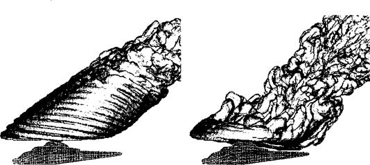
Figure 14.18 shows a calculation of the wake produced by a representative four-bladed helicopter rotor when deep within the VRS. Contrast the aperiodic and somewhat chaotic nature of the wake shown at right in this figure with the orderly wake structure, shown at left, found at higher descent rates. Yet notice how, in the far wake lie the beginnings of the wake instability that will eventually travel down through the wake to engulf the rotor if the descent rate of the helicopter is reduced below the critical value for VRS onset. Although computational techniques such as the VTM and FVM have been very successful in reproducing the basic physical phenomena associated with flight in the VRS [see Brown et al. (2002) for a good discussion], much work still needs to be done in fully understanding the mechanisms leading to the onset of the VRS and the influence of the rotor

Vortex Ring State

Figure 14.18 VTM calculated wake structure for a four-bladed rotor deep within the VRS. Left: with the helicopter in rapid descent the orderly structure of the wake persists for many rotor revolutions downstream. Right: In the VRS at lower descent rates, the wake collapses into a highly unsteady, recirculating, disordered flow. Source: Images courtesy of Gary Ahlin & Imperial College, University of London.

and fuselage geometry on the behavior once in the VRS [see also Bhagwat & Leishman (2000b), Leishman et al. (2002), Brown et al. (2004)].

Ground Effect

Predicting the behavior of the helicopter when near the ground is practically very important because when flying at very low levels the pilot has very little tolerance for patho­logical or unexpected behavior on the part of the aircraft. Aerodynamically, as a hovering rotor is moved from free air or “out-of-ground effect” (OGE) toward the ground, the wake impinges on the ground surface – see Fig. 5.35 previously. Operating “in ground effect” (IGE) results in a change in the inflow through the rotor, and this usually manifests as an increase in rotor thrust for a constant power or, alternatively, as a decrease in power required for a given rotor thrust – see Section 5.8 for details. Forward flight further complicates the aerodynamics of the rotor problem IGE. For example, experimental results (Fig. 5.38) have shown that during transition into forward flight, ground effect can result in an increase in power required for a constant thrust (or a decrease in thrust for constant power), in contrast to the characteristics found for operations in hovering flight IGE. From a handling qualities perspective, large control movements can be required from the pilot during acceleration into forward flight to compensate for rather sudden transitions in the geometry of the flow surrounding the helicopter when near to the ground – see also Fig. 5.37.

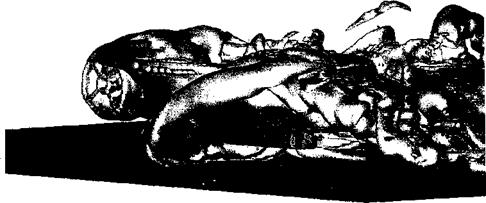
Modeling the effects of the ground on helicopter performance has remained a severe challenge for all computational aerodynamic models because of the extremely complicated behavior of the rotor wake when it interacts with the ground. While the rotor IGE problem has been examined using Navier—Stokes approaches [see, for example, Kang & Sun (1997, 2000)] the problems posed by vorticity diffusion prove a significant impediment to accurate calculations, this time because the dynamics of the rotor wake when near to the ground appear to be controlled by the development and dynamics of unstable structures in the wake that take a very long time (when measured in rotor revolutions) to grow to appreciable amplitudes – see Brown & Whitehouse (2004). In this type of flow situation, vorticity conserving methods such as those described in Section 14.3 come into their own.

For example, Fig. 14.17 shows a calculation of the wake generated by a helicopter in low-speed quartering flight while very close to the ground. An interesting feature at this flight speed is that the wake ahead of the main rotor rolls up to form a crescent-shaped “bow vortex” along the forward edge of the footprint of the wake on the ground – see also Fig. 5.37 for experimental observations of this phenomenon for an isolated rotor. This bow vortex interacts with the ground and with the fuselage of the helicopter, buffeting the aircraft and inducing, potentially, an unacceptable increase in pilot workload in this critical flight condition. At higher flight speeds, the bow vortex is swept away into the flow downstream of the rotor, the wake lifts off the ground and the helicopter essentially behaves as it would out of ground effect.

Vibrations and Acoustics

Today there are strong environmental pressures to reduce the aerodynamic noise that is generated by helicopters, a subject that has already been introduced in Section 8.19. The sources of noise on a helicopter are numerous, but a significant contribution is the

Vibrations and Acoustics

localized impulsive loading of the rotor blades as a result of wake-related В Vis (see Sec­tions 8.16.4 and 10.4.2). There are also strong marketing pressures to improve ride comfort for crews and passengers alike and to reduce maintenance costs. This has driven much re­search to reduce the vibration levels of current helicopter designs. From a modeling point of view, these problems are similar in that they require very high-resolution predictions of the |

unsteady loads on the rotor blades and careful consideration of the structural dynamics of the complete helicopter as a system. In many situations a significant source of noise and vi – ?

bration originates in the aerodynamic coupling between the various rotors of the helicopter. ‘

The situation is particularly severe when one rotor operates directly within the wake of 5

another (for instance, in a helicopter with conventional configuration, the tail rotor might be 1

operating within the wake generated by the main rotor – see Fig. 11.26). Because the wake from the one rotor usually takes a significant amount of time (in terms of rotor revolutions) ]

to convect to the position of the other rotor (see, for instance, Section 11.4), the acoustic and vibration effects induced by rotor-rotor interactions are particularly challenging from a CFD point of view. This is because even a small level of contamination of the solution jj

by numerical viscosity will distort the evolution of the wake and reduce the strength of the

resultant В Vis. This has the effect of downgrading the accuracy of the calculated acoustic radiation or high frequency vibration dynamics of the rotor(s). 1

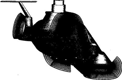
Figure 14.16 shows the results of a coupled rotor-fuselage calculation of the fidelity 1

necessary to form an input to a helicopter acoustic prediction. The tandem rotor case shown |

in this case is particularly challenging from an acoustic prediction perspective because each f

rotor is partially immersed in the wake of the other, and the equal size of both rotors makes і

the calculation particularly sensitive to the detailed geometry of the wake generated by j

the entire system. The need for acoustic fidelity means that the aerodynamic interactions j

between the rotors must be fully represented, and the interaction-induced distortion to both I

U I

wakes can be clearly seen. Notice though that to reduce the cost of the computation to

tractable levels, the fuselage can be represented using a surface singularity method such as j

Vibrations and Acoustics

Figure 14.16 Fully unsteady VTM calculation showing the aerodynamic interactions be­tween the fuselage, forward and aft rotors of a generic tandem helicopter as required for acoustic or vibrations prediction. Image is shown looking upward at the helicopter from below. Source: Richard Brown and Imperial College, University of London.

Vibrations and Acoustics

described in Section 14.7 compared to a direct RANS or other CFD type of calculation. This is a good example of the careful blending or “fusion” of two types of computational tools to achieve aerodynamic fidelity while still retaining a practical level of computational cost for engineering purposes.

14.10.4 Airframe Flows

As explained in Chapter 11, the flow over a helicopter fuselage is extremely com­plicated because it is often dominated by complex viscous effects occurring within the boundary layer. There is often the possibility of grossly separated flow and recirculation especially near regions of high surface curvature. Furthermore, the flow is often highly unsteady as a result of periodic forcing from the nearby passage of the rotor blades and localized interactions with the rotor wake, especially on the tail-boom and empennage under certain flight conditions (see Section 11.2.2 for a detailed discussion). Predictive capabili­ties for pressure and skin friction drag are not yet mature. Current capabilities for design are based on synthesis of component drag using experimental data or by using a combination of experimental data and potential flow theory.

Although panel methods (see Section 14.7) are very flexible and can aid considerably in the design process, they are unable to confidently model viscous effects and separated flows typical of helicopter fuselage shapes and especially hub designs. However, empirical and semi-empirical corrections for the viscous effects can be incorporated into the basic method. For example, a 3-D boundary-layer method can be coupled by means of displacement corrections or by means of a transpiration velocity to the fuselage shape – see Lindhout et al. (1981) and de Bruin (1987). The advantage to the latter approach is that only the right-hand side of Eq. 14.40 is affected, thereby avoiding an expensive recalculation of the influence coefficients at every computational time step. The separated wake can be modeled as a vortical shear layer, the shape of which is either prescribed or made to be force free, as mentioned previously, but this also changes the influence coefficients. Furthermore, a prerequisite is that the separation line be calculated (say from a 3-D boundary layer solution) or deduced from experiment (say from surface flow visualization).

Overall, panel methods and semi-empirical modifications and corrections thereof have been shown to give good predictions of the surface pressure on isolated helicopter fuselages – see Polz & Quentin (1981), Polz (1982), Ahmed et al. (1988). Ahmed (1990) gives a good overview of the various predictive models in current use and their capabilities in predicting pressure distributions and drag on helicopter fuselages. Chaffin & Berry (1994) show that panel methods give good agreement with experimental measurements of fuselage surface pressure, and the predictions are just as good as Navier-Stokes approaches except in regions with large-scale flow separation. See also Narramore & Brand (1992).

CFD methods for airframe design are still in the development stage and are relatively far from being practical for use in routine helicopter fuselage design studies. The use of Navier-Stokes based CFD methods has the potential to help understand a number of prob­lems associated with airframe aerodynamics and rotor-airframe interactional aerodynamics but, like several other problems in helicopter aerodynamics, the proper modeling of flow turbulence and flow separation remains a significant challenge. Another problem with CFD when applied to airframe calculations is the efficient generation of grids. Some progress is being made with hybrid grid systems that couple the advantages of structured and un­structured grids. An example of a CFD grid around a modem military helicopter is shown in Fig. 14.13, showing that this approach is really quite complex compared to a surface panel method such as that shown in Fig. 14.4. Rapid progress in grid generation techniques and solution algorithms is being made – see, for example, Berry et al. (1994), Chaffin & Berry (1994), Duque & Dimanlig (1994), Duque (1994), and Renaud et al. (2004), and it is likely that significant inroads toward an improved understanding of airframe aerodynamics and rotor-airframe interactions using these new methods will occur in the coming years. New numerical algorithms are being developed that will quickly and automatically gen­erate computational grids for CFD analyses. This may allow CFD techniques to be used early on in the design and refinement of airframe shapes – see, for example, Naducci et al. (2003).

Meakin & Wissink (1999) have used overset structured grids to discretize the relatively complicated RAH-66 Comanche fuselage geometry, as shown in Fig. 14.13. See Meakin (1995, 1997) for details. Grid components are arranged to conform to the shape of the airframe, which, perhaps somewhat fortuitously in this case, was designed with relatively flat surfaces to reduce radar returns as a primary goal. Multiple grids facilitate resolution of the viscous boundary layer and important off-body aerodynamics. The near-body portion of the grid was decomposed into 110 components containing a total of approximately

2.2 million grid points. The off-body grid system included 233 components and 5.1 million points for a total of 7.3 million points in all. The flow solution has been used to examine

14.10.4 Airframe Flows

Figure 14.13 The generation of CFD grids around modem military helicopter airframes requires substantial effort in time and cost. Source: Image courtesy of NASA Ames and Robert Meakin, US Army AFDD.

14.10.4 Airframe Flows

Figure 14.14 Unsteady flow over an isolated Comanche helicopter fuselage using a Navier-Stokes method. Particles released from the base of the main rotor hub. Instanta­neous Mach number field on a plane at longitudinal centerline. (Side View). Source: Image courtesy of NASA Ames and Robert Meakin, US Army AFDD.

the effects of the turbulence in the main rotor hub wake on the unsteady aerodynamics at the tail – see Fig. 14.14. This is a good example of where CFD can provide much insight into a real problem that would be extremely time consuming and expensive to examine using either wind tunnel experiments or flight tests – see Berry (1997). Notice though that in this example, no representation of the rotor was included at all within the computation. Indeed, a major future goal is to be able to model, in fully coupled fashion, the interaction between the rotor and fuselage flows. Achieving this goal with the Navier-Stokes equations is still some distance in the future but will allow the unsteady effects of the rotor wake on the dynamics of the airframe to be examined, for instance, to determine the causes of the transient pitching moments that occur on some helicopters as the empennage moves in and out of the rotor wake during changes in flight speed (see Section 11.3.1).

Accurate modeling of the unsteady, localized interactions that take place between the fuselage and vortices from the rotor wake would enable designers to adopt less expensive approaches to minimizing fuselage weight, vibrations, cabin noise, and component fatigue. The results of advanced calculations such as these, when generated early enough in the design process to be of use, might prevent some of the expensive design mistakes that have been made in the past. This is a significant motivation for CFD practitioners. The current state of the art in coupled rotor-fuselage modeling falls somewhat short of this lofty aim, however. One interesting approach results from weakening the coupling between the aerodynamics of the rotor and fuselage – see, for instance, Zori & Rajagopalan (1995), Brezillon (2000), Renaud et al. (2003,2004), and D’Alascio et al. (2003). In this approach, a full Navier-Stokes model for the fuselage is augmented by embedding a series of disks representing the rotors into the computational grid. A pressure jump across the disks is then imposed to represent the lift generation by the rotors, and some representation of the rotor wakes then develops in the computation as a result of the discontinuity in pressure around the edges of the disks. The pressure jump across the rotor disk quite often is calculated by using a comprehensive rotor model (see Section 14.11) to determine the time-averaged loading distribution over the rotor disk for the flight condition being modeled. In this way the time-averaged effects of the rotor on the fuselage can be represented. These methods are ideal for parametric studies at the design stage and can help give key insight to potentially unforeseen problems, even though computation time and cost is still relatively high. Panel methods, however, remain much more cost effective for design purposes than any of the other types of CFD approaches.

14.10.4 Airframe Flows

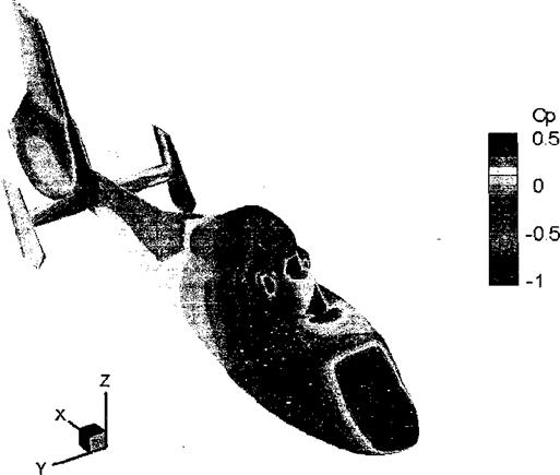
Figure 14.15 Predictions of the time-averaged pressure over the airframe of a helicopter in forward flight using a momentum-source representation of the rotor and a Navier-Stokes based flow solver for the airframe flow. Source: Image from Renaud et al. (2004).

More recent work by Park et al. (2003) and Renaud et al. (2004) has shown the continuing success of Navier-Stokes based methods in predicting airframe loads (see also Chapter 11). An example of such a Navier-Stokes calculation is shown in Fig. 14.15, where good agree­ment with measured airloads was also obtained. It is likely, however, that in the future various types of methods will be used in a more complementary fashion in design work, providing an improved predictive capability of airframe aerodynamics and elimination of possible adverse rotor-airframe interaction problems before helicopters make their first flights. Bear in mind though that the reciprocal coupling, giving the effects of the fuselage on the rotor, are not well represented using this approach and that the similarities between the fully unsteady situation and the aerodynamic behavior of the fuselage when forced by a steady rotor flow can sometimes be rather tenuous.

CFD Modeling of the Rotor Wake

While the flows about the rotor blades themselves have received the most attention, and CFD methods have certainly provided considerable physical insight into the roll-up of the tip vortex and initial formation of the rotor wake, adequate modeling of the subsequent dynamics of the rotor wake has proved a more daunting task. Yet it is the proper modeling of the geometry of the rotor wake that is probably the most important step in the calculation of the entire helicopter flow field. Although there has been some progress in Navier-Stokes based CFD modeling of the rotor wake and the flow field around the entire helicopter, the inability of most current CFD methods to protect this vorticity from the effects of numerical diffusion continues to yield an active area for research. ^Furthermore, the large number of grid points required to define the flow domain for a helicopter rotor continues to challenge even the most powerful computers, with memory demands that are quite formidable even by current-day standards.

One significant problem with wake modeling is that the numerical error in any approx­imation to the Euler or Navier stokes equations tends to introduce artificial diffusion of vorticity, which smears vorticity in the flow more quickly than is observed from experi­ments. An example is shown in Fig. 14.12, and while capturing the key features of the wake

CFD Modeling of the Rotor Wake

Figure 14.12 Navier-Stokes solution of a helicopter rotor wake in hovering flight. 64 million grid points are used. Contours of vorticity magnitude are computed on a cutting plane located at 45° behind one of the rotor blades. Source: Strawn & Djomehri (2002). Image courtesy of US Army AFDD and Roger Strawn.

structure, the coherence of the tip vortex itself is quickly lost to numerical diffusion. This occurs well within a rotor revolution. Based on flow visualization, tip vortices may persist clearly to four or more revolutions. Vortex methods (described in detail in Section 10.7) give a good level of approximation to the problem of defining the strength and vorticity of the rotor wake and have a strong advantage in being able to preserve vorticity independently of grid resolution or vortex age (see Section 10.7.3). Some progress has been made using hybrid schemes where a CFD-based solution for the blade aerodynamics is coupled to one of the vortex wake models discussed in Section 10.7. The inflow (induced velocity field) from the vortex wake model forms a boundary condition to the computational domain of the CFD model, arid data are passed back and forth between the two calculations until con­vergence is obtained. Full-potential methods have also been used for this purpose, and with sufficient engineering judgment have produced remarkable agreement with experimental measurements of the blade pressure distributions, including the critical area near the blade tip. See Caradonna (1990) for a good review of prior work in this area.

Tip Vortex Formation

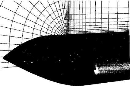
Trailing vortex formation is a complex fluid dynamics problem and is still not yet fully understood. It involves the interaction between strong pressure gradients and viscous shearing forces in the highly 3-D flow near the tips of the rotor blades. Resolving the flow in this region requires a large number of grid points carefully contoured to the blade shape – see Fig. 14.9. While fundamentally the process of vortex formation can only be solved using the Navier-Stokes equations, some success in predicting the behavior of the vortex after formation has been achieved using the Euler equations. Clearly, the proper modeling of the formation of the tip vortex and the subsequent convection of the vorticity through the flow field is probably the most important single step in the calculation of the entire rotor flow field. The difficulties encountered by most Navier-Stokes based CFD methods in preserving the wake vorticity to sufficiently far behind the blades for its effects on the rotor to be captured properly has led to the development of various adaptive gridding or vorticity capturing schemes – see Kim et al. (2002) for a review. Because of the extremely intricate physical processes governing the formation of the tip vortex, most CFD methods (when applied to solve this problem) exhibit solutions that are grid dependent – solution of the governing equations on grids that are sufficiently fine to produce converged solutions is still prohibitive in terms of computational cost for any form of routine use. The goal is to reach some compromise between fidelity and cost, but this requires further research and, especially, validation with experimental measurements. The scope and extent of tip vortex measurements have been discussed in Chapter 10.

Tip Vortex Formation

Figure 14.9 Example of the fine computational grid needed at the tip of a helicopter rotor blade to resolve the roll-up of the concentrated tip vortex using a Navier-Stokes approach. Source: Grid courtesy of Karthikeyan Duraisamy.

To help in reaching this computational goal, various techniques for wake capturing using grid adaptation show promise. These techniques allow grid points to be clustered where the spatial and temporal gradients in the flow are highest and so require a lower overall number of grid points compared to methods using regular grids. Chimera grid systems do much to help resolve the difficulties associated with modeling the flow over blades that are rotating within a domain in which the flow is either stationary or can be represented as a constant free-stream far away from the rotor – see Duque (1992), Strawn et al. (1998), Ahmad & Strawn (1999), Pomin & Wagner (2002), and Strawn & Djomehri (2002). For instance, a surface-conforming grid that rotates with the rotor can be used to capture the flow near the rotating blades while a background Cartesian grid can be used for the wake, with information being exchanged between the grids using various interpolation techniques.

Another method of controlling the dissipation of wake vorticity is by using a vorticity confinement or vorticity embedding technique – see Steinhoff (1987) and Steinhoff & Ramachandran (1990), whereby an “anti-diffusion” term is added to the Euler equations to help control the otherwise nonphysical spreading and diffusion of the tip vortex as it evolves downstream of the blade tip. There are, however, problems with this technique in regard to nonphysical effects and the anti-diffusion must be turned off, for example, for В VI problems. New developments in vorticity embedding techniques for rotor wake predictions are described by Bhagwat et al. (2005), where wake vorticity, as computed using circulation­carrying wake markers, is embedded into the full-potential equation. This novel approach attempts to fuse the best elements of Lagrangian free-vortex schemes with Eulerian grid – based CFD schemes to give a numerically efficient solution for rotor wake problems.

All of these methods are relatively expensive from a computational standpoint and so have not yet made a significant impact on practical rotor design problems. Furthermore, these methods need much further validation, particularly for rotors with advanced tip shapes and also for forward flight applications where shock waves might be present on the advancing blade. Only then can they be used with any confidence to design helicopters. Meanwhile, significant effort still needs to be spent in validating these models against experimental measurements made on properly idealized problems before the entire helicopter can be tackled as a whole. To this end several sets of detailed flow field measurements on generic rotors have provided reliable data for the validation of various types of computational models – see McAlister (1995, 1996), Mahalingam & Komerath (1998), and Martin et al. (2003).

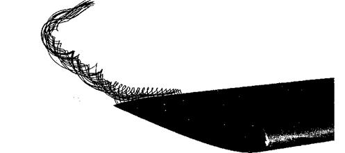
An example of a Navier-Stokes prediction of the rollup of a tip vortex from a helicopter blade is shown in Figs. 14.10 and 14.11, which are from Duraisamy & Baeder (2004). Basically the calculations show that the flow on the lower surface follows a favorable pressure gradient toward the upper surface. Immediately behind the trailing edge of the blade there is evidence of two concentrated regions of vorticity, but these rapidly merge to form a single concentrated tip vortex. This behavior is consistent with experiments – see, for example, Martin, Leishman, & Pugliese (2003). The sharp edges on the blade tip always tend to promote flow separation, and this makes the consideration of viscous effects very important in terms of predicting the subsequent roll up and evolution of the tip vortex. Combined with this is the entrainment of the turbulent vortex sheet trailed from the inner part of the blade. This sheet is formed by the confluence of the boundary layers on the upper and lower surface of the blade – see also Fig. 10.7. The interaction of the sheet with the roll up of the flow from the tip appears to cause large decelerating forces and the generation of turbulence inside the core, emphasizing again the underlying complexity of tip vortex formation and the need for a full Navier-Stokes approach if the roll up is to be predicted properly.

Tip Vortex Formation

Figure 14.10 Particle tracers showing the roll-up of the tip vortex from a helicopter blade predicted using a Navier-Stokes solver. Source: Calculation and image courtesy of Karthikeyan Duraisamy.

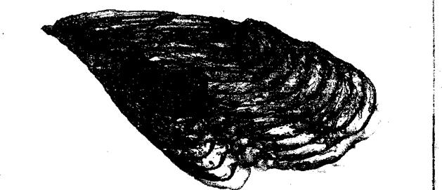
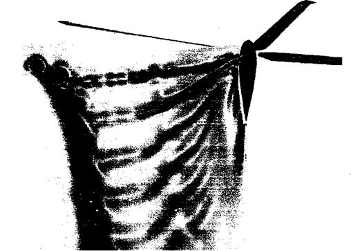
A calculation of the structure of the vortex flow at a later time (145° of wake age in this case) is compared with flow visualization in Fig. 14.11, where there is good qualitative agreement at least. The actual structure of the rolled up tip vortex is comprised of three zones: 1. An inner laminar region with no mixing between layers, 2. A transition region where there are eddies of various scales, and 3. An outer turbulent region. The high swirl

ігрілрЇНрс nPdr tbp xrrvrtPY РПГР rponlf in bt rrb x/qIiipc rtf fbp Inpol Dipbor/Іслп mimkar

TVIVVIUVJ 11VU1 U1V V V/Д. IV/Д WXV ±11 lllgil T U1UVO VI U1V JLWUX 1VJLV11U1UOV11 JLlUiUL/Vl UlVtV

(see Section 10.6.5) and, because of stratification effects, turbulence cannot be generated or sustained. This is essentially a vortex Reynolds number effect and will result in essentially zero eddy viscosity in the core, although this is not properly represented by the turbulence model used within the CFD analysis. These observations suggests that the development of turbulence models used in CFD methods for vortex flows still has some way to go before

(a) Navier-Stokes simulation (b) Experimental observation

Tip Vortex Formation

Figure 14.11 The roll-up and final formation of the tip vortex is a complicated process involving viscous shear and turbulence. Left: CFD calculation showing phase-averaged eddy viscosity contours. Right: Phase-resolved flow visualization. Both results for 145° of wake age. Source: Navier-Stokes calculation and image courtesy of Karthikeyan Duraisamy; Flow visualization courtesy of Manikandan Ramasamy.

predictions of blade generated tip vortices can be made with sufficient fidelity to account for Reynolds number scaling effects.

Dynamic Stall

The problem of dynamic stall has been discussed extensively in Chapter 9. The proper and complete prediction of dynamic stall, however, continues to elude the heli­copter aerodynamicist. This is because dynamic stall is characterized by the appearance of large, recirculating, turbulent separated flow regimes near the surface of the airfoil. While

Dynamic Stall

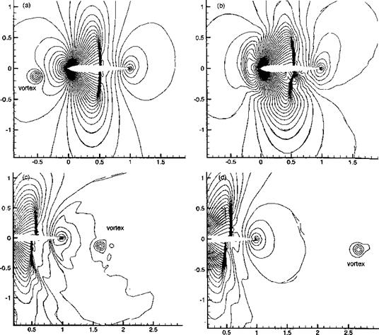
Figure 14.7 A series of predicted pressure fields surrounding an airfoil during a blade – vortex interaction at transonic speeds, (a) Vortex upstream of airfoil, (b) Vortex interacts with airfoil, (c) Vortex passes downstream of airfoil, (d) Vortex passes into downstream wake. Source: Lee & Baeder (2002) and courtesy of Yik-Loon Lee.

parsimonious models including stall effects can be developed for use in rotor analyses (i. e., models for integrated lift, drag and pitching moment – see Section 9.5.1), sensible predictions (as opposed to reconstructions or postdictions) of the overall flow field dur­ing dynamic stall can be obtained only by solving numerically the full Navier-Stokes equations along with a suitable representation of turbulent flow effects. To this end, CFD methods that include some representation of turbulent flow effects via turbulence closure models have begun to show promise in predicting 2-D and 3-D dynamic stall events – see, for example, Srinivasan et al. (1993), Ekaterinaris et al. (1994), Barakos et al. (1998), and Martin, Chandrasekhara, & Geissler (2003). It should be noted, though, that many widely different turbulence models have been developed over the years, the most popu­lar perhaps including those developed by Baldwin & Lomax (1978), Spalart & Allmaras

(1992) , and others, as reviewed by Marvin & Huang (1996), but that the selection of the most appropriate model for any particular flow problem is still very much an open question.

Dynamic Stall

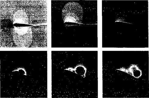
Figure 14.8 A sequence of Navier-Stokes predictions showing the shedding of a leading edge vortical disturbance during dynamic stall at low Reynolds number. Source: Barakos et al. (1998) and courtesy of G. Barakos and D. Drikakis.

An example of a Navier-Stokes prediction of dynamic stall is shown in Fig. 14.8. In these calculations a nonlinear eddy viscosity model was used to represent the turbulence in the flow. Clearly the approach predicts the key characteristic phenomenon of dynamic stall, which is the shedding of a leading edge vortical disturbance – see also Fig. 9.2. However, quantitative predictions of the airloads are not yet satisfactory in the fully stalled regime or during flow reattachment – these techniques have difficulty reproducing the flows at Reynolds numbers and Mach numbers relevant to helicopter rotors. In this regard, the accurate prediction of the transition from a laminar to turbulent boundary layer flow on the airfoil surface prior to the onset of dynamic stall is a key outstanding issue. The complexity of the surface boundary layer flow state on an airfoil under these dynamic AoA conditions is reflected in the measurements of Lee et al. (2000).

Investigation of methods and development of strategies to control and/or alleviate dy­namic stall would appear to yield a prime opportunity for CFD methods, and indeed this problem has received some attention. Yet, no one scheme has yet demonstrated clear ben­efits. The use of zero-mass synthetic jets (see Section 9.12) to delay the onset of flow separation has good potential based on the results of both calculations and experiments. Alternatively, it seems that the use of leading edge slats, or other changes in the leading edge shape of the airfoil, may lead to improvements in alleviating the adverse features of dynamic stall – see Sahin et al. (2000). Studies with variable droop (camber) leading edge airfoils have also been conducted as a means of alleviating dynamic stall related problems – see Geissler & Trenker (2002) and Martin, Chandrasekhara, & Geissler (2003). Any bene­fits, however, have to be balanced against the possibility of introducing adverse effects on the pitching moments from high camber and overall airfoil performance, and this issue has not yet been researched thoroughly enough to be convincing. The payoffs in terms of improved high-lift and low-drag airfoil designs free of dynamic stall is, however, poten­tially enormous, because this could lead to quantum gains in helicopter forward speed and/or maneuver performance.

Applications of Advanced Computational Methods

14.10.1 Unsteady Airfoil Performance

While unsteady aerodynamic effects are intrinsic to the helicopter, there are two unsteady airfoil problems that have received much more attention than others from a mod­eling perspective. These are blade vortex interaction (BVI) and dynamic stall. Both prob­lems are a particularly large source of unsteady airloads and are very difficult to predict. While BVI is a source of both unsteady airloads and very obtrusive noise (see Sec­tion 8.19), its occurrence does not limit the capabilities of the rotor system. As discussed in Chapter 9, the occurrence of dynamic stall, however, can limit both forward flight and maneuver capabilities of helicopters and is a more serious problem from a rotor airloads perspective.

Blade Vortex Interactions (BVI)

The 2-D BVI problem, as previously shown schematically in Fig. 8.36, has been widely addressed using CFD approaches, for example, see McCroskey & Goorjian (1983), McCroskey (1985), McCroskey & Baeder (1985), Singh & Baeder (1996), and Lee & Baeder (2002). While convecting past an airfoil, a vortex of positive circulation produces a downwash velocity while upstream of the blade (airfoil), and this changes to an upwash as it moves downstream. This situation leads to a rapidly and continuously changing angle of attack, resulting in highly unsteady aerodynamic loads – see Section 8.16.4 for an analysis of the problem using linear unsteady airfoil theory. The BVI problem usually requires compressibility effects in the flow to be accounted for if the correct amplitude and phasing of the airloads is to be calculated. In some cases, such as near the tip of the blade, the flow may be transonic. In this case the BVI problem is inherently nonlinear and quantitative prediction of the airloads requires advanced, nonlinear CFD methods for proper solution.

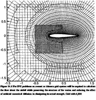
A problem that arises in such CFD solutions, however, is the need to preserve the physical strength of the vortex for relatively long times before and after its interaction with the blade or airfoil. This has been done relatively successfully using adaptive or chimera-type overset grids, such as in the example shown in Fig. 14.6. In this example, an О-type grid is wrapped around the airfoil and two overset H-grids are moved relative to the О-grid, tracking the vortex as it passes by the airfoil. The finer resolution of the flow afforded by the overset grids acts to reduce the numerical errors in the region of strong velocity and pressure gradient surrounding the vortex, and thus helps to reduce artificial numerical diffusion of the vortex during its interaction with the airfoil.

Figure 14.7 shows the complexity of the flow during a BVI event where shock waves are present in the flow. This might be the case, for instance, if the BVIs are encountered on the advancing blade at high forward flight speeds. The flow is calculated using an Euler CFD-basea approach with a chimera-type overlapping grid – see Lee & Baeder (2002). The vortex is initially well upstream of the airfoil and the flow about the airfoil is benign, except of course for the presence of the upper and lower surface shocks. As the vortex approaches the airfoil, rapid changes occur as the induced velocity field from the vortex alters the AoA of the airfoil and its pressure distribution. In this case the vortex passes about 0.125 chord lengths below the airfoil, so the interaction is relatively strong. Notice the effect of the vortex on the lower surface shock wave – as the vortex passes by the shock bifurcates, adopting a lambda shape for a short period before returning to its original geometry. Amazingly, despite the high pressure gradients in the flow at and near the shock wave, the vortex emerges from the interaction with the airfoil and the shock wave in a

Подпись: I,

Applications of Advanced Computational Methods Подпись: Figure 14.6 For BVI problems an overset or chimera grid system will be required to calculate the flow about the airfoil while preserving the structure of the vortex and reducing the effect of artificial numerical diffusion in dissipating its actual strength. Grid with 6,800

Lee & Baeder (2002) and courtesy of Yik-Loon Lee.

relatively undisturbed form. According to Fig. 14.7(d) the vortex does, however, appear to lose its initial radially symmetric form.

Of course, the prediction of BVI in 3-D viscous flow and over the entire rotor is the ultimate goal for CFD methods. This is, however, an extremely ambitious task, requiring high-resolution calculations using many tens or hundreds of millions of grid points. One outstanding issue is how to capture 3-D vortical flows accurately using 3-D overset grids. Grid refinement continues to be limited by computer memory and speed, and it would seem that approaches based on indefinite grid refinement will probably not be that useful in the shorter term. As is clear from the foregoing 2-D example, overlapping grids offer a very powerful and natural approach to solving the flows found on the various stationary and moving vcomponents of helicopters, however. The alternative of regenerating the grid at every time step, change in flight condition, or whatever, is expensive and prohibitively time consuming. A combination of refinement and proper placement of overset grids (say, for example, using the FVM or VTM as guidance) would be a very powerful technique if properly developed, and this is a promising area for further research.