Category Principles of Helicopter Aerodynamics Second Edition

Lifting-Line Blade Model

A very useful, but somewhat simplified, computational model of the aerodynamics of a rotor results from treating the blades as a series of 2-D blade elements, in the manner introduced in Chapter 3. If the velocity induced by the vortical wake of the blades can be calculated, then the induced AoA along the length of each blade can be found. The lift on the blade elements can then be determined and thus, by radial integration, the total blade lift. Lifting-line blade models that exploit this approach have found much use in helicopter rotor analyses and are to be found as the basis of nearly all forms of comprehensive rotor analysis (see Section 14.11). ,

To use the lifting-line model properly, though, the effects of the wake on the loading on the blade must be fully coupled to the circulation that is trailed (and shed) into the wake. This allows some 3-D effects to appear in the spanwise distribution of the blade loading, but because of small disturbance assumptions the method is not powerful enough to account completely for the strong 3-D flow effects found near the tip and root of the blade or near localized blade-vortex interactions, for instance. In principle, the models used in the helicopter field are similar to those used for fixed-wing analyses [see, for example, Houghton & Carpenter (1993)]. The lifting-line approach must be formulated carefully for use in rotating-wing applications, though, because the wake cannot be assumed to be planar, nor to extend downstream to infinity. Many different formulations can be found in the literature, with slight variations in assumptions in regard to the wake system. Although the basic principles are the same, the numerical formulation can vary substantially between implementations.

A generic formulation of the lifting-line problem will be described. For consistency with the results of Section 14.8, the blade is modeled as a vortex of strength Гb(y) that is “bound” to the aerodynamic center (1/4-chord). Then, using the Kutta-Joukowski theorem, the lift per unit span dL is given by

dL(y) = pV(у)Гb(y) dy = іpV(y)2cCi(y) dy

— ^pV(y)2Cia(y)ue{y)c dy, (14.52)

Подпись: V(y) ae(y) Подпись: Г b(y) 2TC{C/2) Подпись: (14.53)

where ae is the “effective” AoA of that section and C/a is its lift curve slope. Often C/a is given the value 27r, being the lift curve slope of a 2-D thin airfoil in incompressible flow (see Section 14.8), but in practical applications the lift curve slope of the airfoil section at the appropriate combination of Mach number and Reynolds number can also be used. Assuming a thin airfoil and rearranging the terms gives

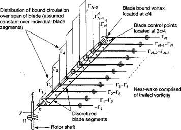
For a 2-D airfoil the bound vortex is an infinite line vortex and must have a strength that is defined on the basis of the downwash at a distance c/2 from the 1/4-chord, that is, by a condition of no flow penetration that is imposed at the 3/4-chord. This is consistent with the 2-D thin airfoil model of the problem that was described in the previous section. To extend this concept to three dimensions the blade is divided into N elements, as shown by Fig. 14.5, and a control point is placed at the 3/4-chord of each element. The normal velocity induced at the control point of panel і by the vorticity bound to element j can be written in terms of a matrix of influence coefficients, Ib, so that

Ubij rbj = Vat. (14.54)

The objective is to solve numerically for the distribution of bound circulation over the blade, Tb., which satisfies the no-flow penetration condition simultaneously at all of the control points on the blade. On the ith element of the blade,

N

Y, Vb + /»„].• J Г„,- = V № – фі) = Vae,, (14.55)

7 = 1

where Inw is the influence of the “near-wake” that must trail from the edges of the blade element. The near wake is usually modeled by a series of horseshoe vortices or vortex arcs

Lifting-Line Blade Model

Figure 14.5 Lifting-line model representing the near wake trailed from a rotor blade.

that trail downstream a finite distance, often to 15-30° of wake age, behind the blade. On the right-hand side of the equation, </>,■ contains the induced contributions from the remainder of the vortical wake (the “far wake”) and must exclude all of the induced effects from the parts of the wake that are defined as being part of the near wake. Applying this equation at all control points results in a linear set of simultaneous equations of the form

Ub + ІпіиІІГь) = {V (в – ф)}, (14.56)

from which the span wise loading (circulation) Г ъ can be obtained by standard numerical methods for solving systems of linear simultaneous equations. Both direct and iterative methods can be used, although direct methods are usually preferable because of their supe­rior numerical behavior. In general, both Іь and Inw are matrices that are fully populated, although strongly diagonally dominant. Hence the structure of Іь and Inw cannot usually be exploited to simplify the numerical solution of Eq. 14.56.

From the resulting distribution of circulation along the blade span, the strengths of the vortices that trail from the edges of the blade elements (Fig. 14.5) can be calculated. These provide a boundary condition for the far vortex wake, which can be represented using a FVM, for instance. As mentioned previously, in many rotor wake modeling applications only the tip vortex is modeled, primarily for computational efficiency, but also because this vortex is the dominant flow structure in the rotor wake. This is because the high concentration of aerodynamic loading over the tip region of helicopter blades generally results in a powerful vortex rolling up and trailing from a point very close to the blade tip. It is often assumed for modeling purposes that all of the circulation outboard of the position of maximum bound circulation on the blade rolls up into this tip vortex. This is equivalent to assuming that the circulation about the tip vortex is the same as the maximum value of the bound circulation on the blade – see Question 14.6. This assumption can be used to define the initial strength (or circulation) of the vorticity in the far wake. The actual strength and initial location of the tip vortex may also be adjusted based on empirical data, if these are available. See Bhagwat & Leishman (2000a) for measurements of the relationship between the blade bound vorticity and the circulation in the trailed wake for a rotating blade.

Thin Airfoil Theory

Подпись: ACp{a, в) = 4 Thin Airfoil Theory Подпись: (14.44)

Thin airfoil theory has been alluded to several times in earlier chapters. The gov­erning equation for thin airfoil theory is Laplace’s equation in two dimensions. The idea is that the airfoil is replaced by a camberline (which is a flat plate if the airfoil is uncambered) on which a vortex sheet singularity of unknown strength, y{x) is placed. The strength of this vortex sheet is determined by satisfying flow tangency on the camberline of the airfoil in conjunction with the Kutta condition at the trailing edge, that is, у {ТЕ) = 0. Solutions are usually obtained by expressing the vortex sheet strength as a Fourier series, and then calculating the coefficients in this series. See Glauert (1947) for details of the method. In most cases it is only the integrated lift and pitching moment on the airfoil that is required and not the chordwise loading. These can be determined using only the first three coefficients in the Fourier series. The general form of the chordwise loading on the airfoil is

Thin Airfoil Theory Подпись: and An Подпись: 2 7Г Thin Airfoil Theory Подпись: (14.45)
Thin Airfoil Theory

where в — cos!(1 — 23c) and x = x/c. The coefficients Aq and An are given by the equations

where у = y(x) describes the camberline of the airfoil. The lift and pitching moment co­efficients are given by

АГ

n

A2

Ao + t

’ CmLE=~2

Ao + A ——

СИ1/4 = -^[А1-А2]. (14.46)

Thin Airfoil Theory Подпись: Ґ1Л Al  i-T.-r ,, (14.48)

Note that for a noncambered airfoil (dy/dx = 0), Aq — a and An = 0 if n > 0, giving

Thin Airfoil Theory Подпись: (14.49)

Thin airfoil theory is very powerful despite its simplicity and is particularly useful in helicopter analyses, especially during preliminary airfoil design, because it allows a rapid estimation of the pitching moment resulting from any given camberline – see Section 7.7.3. The theory also forms a basis for understanding the elements of unsteady airfoil aerody­namics, as has been examined extensively in Chapter 8. An interesting result is obtained by assuming that the vortex sheet strength is all lumped or “bound” to vortex of strength Г*, placed at the aerodynamic center (1/4-chord) of the airfoil section, that is, so that

Using the Kutta-Joukowski theorem, the lift per unit span

Подпись:Подпись: (14.51)L = рУооГ» = X-pVlcCh

where Ci = 2not in 2-D flow. The only way Eq. 14.50 can be satisfied is if

Гь = TtVooCa.

This is equivalent to enforcing the flow tangency condition only at the 3/4-chord of the airfoil. (The 3/4-chord position is sometimes called the rear neutral point after Pistolesi and Kussner.) This result is equivalent to saying that the lifting properties of an airfoil, in steady flow at least, can be modeled by placing the bound circulation at the 1/4-chord and satisfying flow tangency at the 3/4-chord. This result is fundamental to the development of the 3-D lifting-line models described in the next section.

Surface Singularity Methods

Surface singularity or panel methods are based on the assumption of small dis­turbance, incompressible irrotational flow, for which the governing equation is Laplace’s equation (Eq. 14.36) for the velocity potential. The basic approach is described by Hess & Smith (1962), Rubbert & Saaris (1969), Morino (1985), Hess (1990), and Katz & Plotkin

(1991) . These methods can be used to model the flow over helicopter fuselages, and with
extensions to account for the vorticity distribution in the wake behind the body, the flow over wings and rotor blades too. The idea is that surface singularities of unknown strength can be distributed over the body surface. After determining the strengths of the singularities by imposing a condition of flow tangency on the surface, the surface velocities, and hence the aerodynamic loading on the body, can be calculated. For an engaging modem treatment of the various types of panel methods, see Katz & Plotkin (1991). Large computer codes that use panel methods are commercially available and are in widespread use in the helicopter industry. See also Maskew (1982) for a good summary of the general approach.

Classical panel methods have found considerable use in helicopter applications for airfoil and fuselage design. The principles of both 2-D and 3-D panel methods are similar. To illustrate the principles, consider the flow about a 2-D airfoil. The airfoil surface is replaced by distribution of N discrete panels, and each panel і contains a singularity distribution that can be described by a velocity potential function фі. This means that the total potential induced by all the singularities in the flow is

N

Подпись: (14.37)Ф =

i = l

where the constants y, must be found subject to the boundary condition that the flow must be tangential to the surface at N discrete collocation points xj on the surface. That is,

(V0(*7-) + Voo) ■ nj = 0, (14.38)

where n j is the outward pointing normal unit vector at the j th collocation point. Usually the collocation points are selected to be the midpoints of the panels. If the panels contain vortex singularities that vary linearly in strength over the area of the panel, then with N panels there are N equations containing N + 1 unknowns. The Kutta condition at the trailing edge of the airfoil provides the auxiliary equation required to solve the problem uniquely and to define the airloads on the airfoil. The equations governing the problem can be expressed in the form

where A = A-j = Wфi(xj) • nj is a (N + 1) x (iV + 1) matrix of influence coefficients. The influence coefficient А,-j is effectively the normal component of the velocity induced at the collocation point on panel j by the singularity distribution 0, on panel і and depends on the relative distance between, and orientation of, the two panels. Notice that solving Eq. 14.39 involves finding the inverse of the matrix of influence coefficients, and, besides the calculation of the influence coefficients themselves, this inversion is the primary com­putational expense involved in the panel method. If the angle of attack, a, is included in the vector on the right-hand side of Eqs. 14.39, then the influence coefficients need only be calculated once, however. Once the singularity strengths у,- are known, the loading on the airfoil follows immediately.

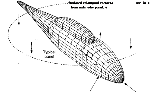
Panel methods have also been used to model the aerodynamics of helicopter airframes. In such an application, the fuselage surface might be represented by N small, flat, quadrilateral panels onto which singularities in the form of sources and sinks and/or doublets are placed

Discretization of body Free-stream Va

surface (source/sink or doublet panels)

(see Fig. 14.4 for an example). The principles are very similar to the 2-D case, but the size of the numerical problem becomes much larger. Assume for illustration that only source singularities are used. If the singularity strength on the ith panel is cr, , then the velocity induced by this panel at the control point on the yth panel can be written as A, j a,-. At the jth control point, the component normal to the surface of the velocity induced by all N sources is then

N

Vj = Y A‘j ai for/ Ф J – (14.40)

/=i

The boundary condition of flow tangency is imposed at the control point of each panel to allow the unknown singularity strengths о,- to be evaluated. So, for instance, if is the velocity at panel j as a result of the motion of the fuselage, the rotor-induced velocity and so on, the component of VCXj normal to panel j will be • hj, where hj is the unit normal vector to panel j. Therefore, at the jth panel

N

Y, Aij a і + Voo. • Hj = 0. (14.41)

/=1

One equation such as this applies on each of the N panels. This leads to a set of linear simultaneous equations that can be used to solve for the singularity strengths, a, , using standard numerical methods of linear algebra. The governing equations can be written in matrix form as

Подпись: (14.42)

Surface Singularity Methods

[Aij]{ai} = -{Voo – nj},

with solution

Подпись: (14.43){ct,) = [Aij]_1 {-Voo-ny},

which involves finding the inverse of the influence coefficient matrix. Once the values of ot are obtained, the velocity components tangential to the panels can be obtained, and hence the pressure distribution over the fuselage follows using Bernoulli’s equation.

Normally thousands of panels are required to resolve adequately the complex shape of a helicopter fuselage and care must be taken, for instance, to concentrate a sufficient number of panels in regions of high surface curvature such as near the rotor hub. Because the numerical cost of panel methods is of order N3, their use is by no means inexpensive even on a modem computer. But they are considerably less computer intensive than most other types of CFD methods, however. As an enhancement to the basic panel method, the solution of the momentum integral equation from boundary layer theory allows displacement corrections to be made to solutions obtained from the panel method, thereby allowing viscous effects (but not flow separation) to be modeled. The effects of flow separation can be included, however, by extending the surface singularities off the airframe as free shear layers – see Polz (1982), Le et al. (1987), de Bruin (1987), Ahmed et al. (1988), Ahmed (1990), and Katz & Plotkin (1991). Overall, if suitable care is taken in the distribution of panels on the surface of the fuselage, the 3-D surface singularity method can be used to obtain quite credible predictions of the loading on an airframe – certainly to the fidelity required for preliminary design (see also Section 14.10.4). See Chaffin & Berry (1994) for a further discussion of the predictive capabilities of panel methods compared to measurements and other forms of analysis.

Potential Equations

A further simplification to the governing equations of the flow can be achieved by assuming that the flow is irrotational, that is, V x V = 0. In this case the velocity field can be expressed as a gradient of a potential function ф so that

V = V0. (14.32)

Подпись: V2</> Potential Equations Подпись: = 0, Подпись: (14.33)
Potential Equations

Care must be taken with this approach, however, especially given the essentially rotational nature of the flow in the wake. The potential equations can be expressed in many ways, but one form, used commonly to model compressible flows, is

where V — I V|. This form of the potential equation is usually referred to as the full-potential equation because no terms have been neglected in its derivation from the Euler equations – see Sankar & Prichard (1985), Strawn (1986), and Strawn & Caradonna (1987). For tran­sonic flow problems, all the terms are important if the characteristic nonlinear variation of the flow properties with Mach number is to be represented properly. If small disturbances can be assumed then some of the terms are of higher order and can be neglected, however. The transonic small disturbance (TSD) equations are a subset of the full potential equations and can be written in the form

Афц+Вфхі = Ех+фгі+СфуУ+ cross terms and low-order derivatives. (14.34)

The nonlinearity of the problem is contained in the Fx term, which involves фх and ф2. Historically this was one of the first flow equations ever to be tackled by numerical means, launching the field known today as CFD – see Caradonna & Isom (1972) and Caradonna

(1990) .

If all the higher-order terms are neglected, the TSD equation reduces to a wave equation of the form

4-0« = V2*, (14.35)

aX>

where Яоо is the free-stream speed of sound. A final simplification is to assume incom­pressible flow (a0о —» oo), in which case the velocity potential is governed by Laplace’s equation, that is,

V20 = 0. (14.36)

A feature of this equation is that it is linear and so it allows complex flows to be synthesized by combining more elementary flows. This equation underlies the vortex methods de­scribed in Section 14.4 as well as the surface singularity methods described in the following section.

Boundary Layer Equations

At the Reynolds numbers typical of helicopters, the viscous terms in the Navier – Stokes equations are significant only in a thin shear layer, called the boundary layer, near the surface of the vehicle. To model the flow in this layer, a simplified subset of the Navier – Stokes equations can be derived that exploits the fact that the length-scale of the variation of the flow variables is very much smaller normal to the surface than parallel to the surface.

The chief advantage of the boundary layer approach is that it allows an inviscid “outer” solution (calculated for instance using the Euler equations or a potential flow solver) to be modified for the effects of viscosity near the surface of the rotors and fuselage. This approach leads to a class of numerical techniques known as zonal or viscous-inviscid interaction methods. Such methods have proved very useful in airfoil design, but can also be useful

in predicting rotor and airframe loads on helicopters. The basic principle is first to solve the inviscid flow problem and then to solve the boundary layer equations. The inviscid solution is then repeated after applying a correction to take into account the effect of the finite thickness of the boundary layer on the outer flow. The resulting solution thus yields, to first order, a high Reynolds number solution to the Navier-Stokes equations. Care must be taken, though, where grossly separated flows are encountered, for instance, in the lee of bluff fuselages and cowlings, because under these conditions the basic assumptions of the boundary layer approach are invalidated.

Consider the situation in two dimensions. If x is in the direction parallel to the surface and у is normal to the surface, then, as the Reynolds number of the flow becomes very large, the Navier-Stokes equations for an incompressible flow reduce to

Подпись:3 и dv

—— 1— =0 (continuity),

ox dy

3и ди 1 dp 32u

и ——-v— =———— b v—- (^-component of momentum),

Эх oy p ox dy1

Boundary Layer Equations(pressure gradient normal to surface)

because the gradients of the fluid properties in the x direction become much smaller than the gradients in the у direction. If the flow is unsteady, then the momentum equation

Подпись:

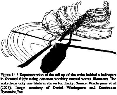
Подпись: Figure 14.3 Representation of the roll-up of the wake behind a helicopter in forward flight using constant vorticity curved vortex filaments. The wake from only one blade is shown for clarity. Source: Wachspress et al. (2003). Image courtesy of Daniel Wachspress and Continuum Dynamics,'Inc.

3 и ди ди 1 dp д2и

— – b и— – J – v— =—————– Ь v——

31 дх 3у р дх 3у2

should be used instead. At the edge of the boundary layer у = 8, where 8 is the boundary layer thickness [which by definition is where the local velocity approaches 99% of the external flow (or edge) velocity, Ue(x, t) – see Section 7.3.2]. Because the pressure across
the boundary layer (i. e., normal to the surface) is constant (Eq. 14.25), the pressure at any point on the surface is taken to be the pressure just outside the boundary layer. The momentum equation outside the boundary layer can thus be rewritten as

Подпись: (14.27)dUe dUe = 1 dp

31 e dx p dx

Boundary Layer Equations Подпись: (14.28)

Using this equation, the pressure can be eliminated from the problem and the momentum equation within the boundary layer becomes

Associated with the solution of the boundary layer equations is the concept of a dis­placement thickness, 3*, which is written as

Подпись: (14.29)‘-/Л’-*)*-

Подпись: I-Подпись: іThe displacement thickness is a measure of the extent to which, if the effects of the boundary layer are to be included in an inviscid model of the flow away from the surface, the shape of the surface might be displaced away from the original surface to yield the same flow rate as in the viscous flow with the boundary layer present. This is same as saying that the external, inviscid, flow about the body can be obtained by solving the equations about a shape that is generated by adding the displacement thickness to the actual shape of the body. This type of approach is an example of a so-called weak interaction method. Although obviously still an approximation, and apart from the restrictions on the method mentioned above, this approach yields more representative flow solutions at the Reynolds numbers appropriate to helicopters than if the viscous effects were completely ignored in the calculation.

Подпись: ft l l In many engineering problems the details of the flow inside the boundary layer are of no interest and only the effects of the boundary layer are needed. For example, the shear stress on the surface (to estimate the viscous drag) and the boundary layer displacement thickness (to perform a correction to the external flow) might be required. These variables can be calculated directly from an integrated form of the boundary layer equations, called the momentum integral equation, usually attributed to von Karman (1921). In this case the governing equation is

d<) d Hp Tim

—{U2e0) + 8*Ue —- = —, (14.30)

dx dx p

where tw is the shear stress on the wall (surface) and

/ и / і/

e=!Al~tAt)dy – <1431)

is the so-called momentum thickness. This equation is very general because no assumption is made about the relationship between zw and the velocity gradient, and so the equation can apply to both laminar or turbulent boundary layer flows. After choosing a suitable form for the velocity profile across the boundary layer, the momentum integral equation can be solved to find the key variables describing the properties of the layer (i. e., 8, 8*, 0, and xw). While in some cases solutions to the momentum integral equation can be found in closed form, in most cases numerical solutions must be obtained. See Houghton & Carpenter

(1993)

Подпись: Hr I

or Katz & Plotkin (1991) for a survey of the various possible approaches.

Vortex Methods

The free-vortex method (FVM) is a technique related to the VTM (see Sec­tion 10.7.6). In many practical problems involving the rotor wake it can be justified that the structures produced by viscous effects (such as the internal structure of the vortices making up the rotor wake) have very much smaller length scales compared to the structures produced by purely potential flow (such as the global deformation of the wake). This allows concentrated regions of vorticity to be represented as singularities within the flow, in which case Eq. 14.15 reduces to the inviscid equation

Helmholtz’s second law states that the vortex lines move as material lines – see Saffman

(1992) . This can be shown as follows. Consider a material segment 5s somewhere in the flow. The equation of motion for this vortex segment in Lagrangian form is given by

Vortex MethodsПодпись:(14.20)

(14.21) for some time-independent a. If at some time t = to the material line happens to coincide with the vortex line, then (u>o — o-5so) = 0. If the velocity field is continuous, then it follows that Eq. 14.21 has only one unique solution, namely (со — a5s) = 0. In other words, the local vorticity translates and rotates for all time as a vector that remains aligned with the material segment 5s.

In the vortex method, the dynamics of material lines in the fluid can be used to represent the dynamics of a set of discrete vortex segments, which can be defined in 3-D space by poi nts or Lagrangian fluid markers – see Fig. 10.26 for instance. The motion of the material lines (and fluid markers) reduces to a simple advection equation of the form

Подпись: (14.22)— =V, r(r=0) = r0,

dt where г is the position vector of a marker, Tq is the initial position vector of the marker, and V(r) is the local fluid velocity at that marker. The solution of Eq. 14.22 is complicated significantly, however, by the highly nonlinear nature of the velocity field, V.

There are many different approaches to the solution of Eq. 14.22 for helicopter rotor wake problems, all of which involve the repeated evaluation of the Biot-Savart law to calculate the velocity field У in terms of the vorticity in the flow. Both time marching (time integration) and relaxation (iterative) methods can be employed – see Leishman, Bhagwat, & Bagai (2002) and Wachspress et al. (2003). An example of a wake calculation using the vortex method is shown in Fig. 14.3. The numerical technique used to obtain the results illustrated here was based on a refinement of the basic FVM using lines of constant circulation strength (see also Fig. 10.26). The vortex method has the advantage of being free of artificial diffusion; the vortex filaments are essentially self-adapting and do not dissipate. This means that the wake well downstream of the rotor remains very well defined compared to most Eulerian grid-based solutions, although care must be taken to avoid deterioration of accuracy if the marker points used to define the wake structure begin to drift apart downstream of the rotor.

Vorticity Transport Equations

The use of vorticity transport models has seen some recent success in modeling the vortical flow structure of helicopter rotor wakes. This approach is intermediate between the Navier-Stokes and Euler based CFD techniques described in the previous sections and the ffee-vortex method (FVM) discussed in detail in Section 10.7.6. As previously mentioned, discretized approaches to solving the governing equations of the flow can suffer excessively from numerical dissipation of vorticity, for instance, in the rotor wake. This renders these approaches effectively useless for calculations where flight conditions force the vortical structures in the rotor wake to persist near the rotor for very long times, such as for flight in ground effect or in descending flight. Flight approaching the vortex ring state proves to be a particularly good example – see Section 14.10.7. If the flow can be assumed to be incompressible (generally a reasonable assumption in the rotor wake), vorticity transport methods can be used to overcome the problem of diffusion of vorticity. This is done by solving the governing equations for the flow not in the conservative variable form described previously but directly in terms of the variables of vorticity ш and velocity V.

Vorticity Transport Equations Подпись: (14.14)

If the flow is assumed to be incompressible, then, in an Eulerian frame of reference, the Navier-Stokes equations can be rewritten as

where the vorticity w = V x V. The first term in this equation is the temporal evolution of vorticity, the second is an advection term, the third is a strain or stretching term, and the fourth represents viscous diffusion effects. Notice that the stretching term can only exist in a 3-D flow. Alternatively, in Lagrangian form this equation can be written as

Deo

—— = (ш ■ V)V + yA – u>. (14.15)

strain diffusion

Equation 14.15 defines the change of vorticity of a fluid element moving with the flow. This is a Lagrangian representation and is a useful frame of reference to adopt for the vortex methods outlined in the following section (and detailed in Section 10.7.6), whereas Eq. 14.14 defines the change of vorticity at a specified point in the flow, which is an Eulerian representation and is a more useful description for the grid-based CFD method described below.

If the vorticity field is known (or initially assumed), then the velocity field can be calculated using the Biot-Savart relationship

V2V = – Vxw. (14.16)

In practical applications it can be easier, however, to solve this equation in its more familiar integral form as

V(x) = – f – p—~ x ш(у) dy, (14.17)

477- J |X – y|3

The use of this equation is explained in more detail in Section 10.7.1.

The vorticity transport model (VTM) developed by Brown (2000) and Line & Brown

(2004) employs a direct computational solution of Eqs. 14.14 and 14.16 to calculate the evolution of the rotor wake. The development of the rotor wake can be modeled using the vorticity transport equation if the essentially viscous process of vorticity creation as a byproduct of the generation of aerodynamic loads on the rotor blades, fuselage, and so on, is modeled by appending a source term S to Eq. 14.14 to yield

+ (V • V)uj — (u> • V)V = vA • o/+ S. (14.18)

at

If a suitable model for the generation of aerodynamic loads on the system can be defined in terms of the flow velocity V, then the source term allows the effects of the strength and geometry of the vorticity distribution in the rotor wake to feed back into the aerodynamic loading and blade response. This can be done, for instance, by writing S in terms of the shed and trailed vorticity from the blades using a lifting-line or lifting-surface approach – see Section 14.9.

After casting the equations on a structured Eulerian computational grid surrounding the rotor, the velocity field is obtained either by solving Eq. 14.16 for instance by cyclic reduction [see Schumann & Sweet (1976)] or by evaluating Eq. 14.17 using a fast multipole summation technique [see Line & Brown (2004)]. The key feature of the method is that the convection

Vorticity Transport Equations

Figure 14.2 Longitudinal plane through the wake of a rotor in low speed forward flight as calculated using the VTM approach. Notice the upwash at the front of the rotor disk and the development of a vortex pairing instability in the wake downstream of the rotor, a physical feature only observed if the vorticity can be preserved for many rotor revolutions. Source: Image courtesy of Andrew Line & Imperial College, University of London.

of the vorticity through the computational domain is computed using a total variation diminishing (TVD) algorithm [for instance, Toro’s Weighted Average Flux method – see Toro (1989)] that acts directly on the vorticity field, rather than on the density, pressure, and velocity as in more conventional CFD approaches. Very tight control is, therefore, maintained in the VTM over the rate of dissipation of vorticity in the wake and so vortical structures retain their strength and geometry, and are sharply resolved – even though their interactions with the rotor may continue over many rotor revolutions.

An example of a VTM calculation of the wake of a rotor operating in level forward flight at low airspeed is shown in Fig. 14.2. Notice how three levels of grid refinement have been used to resolve the flow very sharply near the rotor while reducing the computational expense in capturing the wake far from the rotor where it has a smaller influence on the rotor behavior. This type of model is very good at representing blade-wake interactions, as well as the wake-wake interactions that, as shown in Fig. 14.2, drive the development of very complicated flow patterns far downstream of the rotor. Although the VTM provides a very complete model for the evolution of the stmcture of the rotor wake, like all grid – based CFD approaches it is computationally expensive for routine use in parametric design applications. It does, however, offer one approach for the practical investigation of a wide range of helicopter rotor wake related issues until such time that Navier-Stokes solutions become more practically feasible.

Euler Equations

If turbulence and viscous effects do not need to be resolved (assuming these can be treated as weak effects in a given application), then the problem of gridding the compu­tational domain to extremely fine resolution is obviated to some extent, allowing compu­tational costs to be reduced by orders of magnitude. If the flow is assumed to be inviscid, then the Navier-Stokes equations reduce to a simplified set of equations, called the Euler equations, which can be solved instead. By simply dropping the viscous terms from the full Navier-Stokes equations, the Euler equations can be written in tensor differential form in Cartesian, nonaccelerating coordinates as

— – f = 0 (Mass conservation), (14.10)

Подпись: upUj) 3 (pUjUj) 31 3 Xj Подпись: — (Momentum interchange), 3 Xi Подпись: (14.11)

31 dxj

Подпись:Подпись: (Energy interchange).3 (ph) d(phu;) dp dp

———– 1——– — =——— b U;–

31 dxj 31 3 3Xj

Alternately, by dropping the viscous terms from Eq. 14.8, the Euler equations can be written in conservation form as

Подпись: a.In practice the Euler equations have been found to yield a very good approximation to the high Reynolds number flows around real helicopters. Although the viscous terms are neglected, numerical solutions to the Euler equations can provide considerable insight into rather complicated flows. Vorticity in an inviscid flow, such as that governed by the Euler equations, should convect freely without any dissipation or diffusion. But the process of discretizing the Euler equations still leads to nonphysical numerical dissipation and diffusion of vorticity, however. This is an artifact of discretizing the spatial derivatives using Taylor’s series approximations. Fortuitously, though, this behavior may improve, to some extent, the ability of numerical solutions to the Euler equations to mimic reality. For instance, airfoils and rotors modeled using the Euler equations should not generate lift, because the Euler equations by themselves do not allow circulation to be developed – this process takes place through the action of viscosity. In practice, however, the numerical solution of the Euler equations introduces an artificial source of viscosity, even an infinitesimal amount of which will allow the essentially viscous problem of flow over a lifting surface to be modeled using an inviscid set of equations. The Euler equations have been used with a great deal of success to predict aerodynamic loadings on rotor blades – see, for example, Roberts & Murman (1985), Sankar et al. (1986), and the reviews by Caradonna (1990) and Conlisk (2002).

Despite the limitations of using the Euler equations, Euler-based CFD methods have helped the helicopter manufacturing industry to gain new insight into many complex rotor problems and has allowed the limitations of simpler models (such as those used in compre­hensive analyses; see Section 14.11) to be better understood. Yet, the high computational costs and numerical problems encountered in preserving the concentrated vorticity within the rotor wake have hindered application to many practical problems that require an ac­curate, long term treatment of the rotor wake, say over several rotor revolutions. This is particularly problematic for problems in В VI noise prediction. The inability of most Euler – based computational techniques to preserve the vorticity in the wake from dissipation at the hands of artificial numerical diffusion continues to form an opportunity for good research. Alternative methods such as vorticity transport and vortex methods continue to offer a good compromise in this regard. Although Euler-based methods will eventually be adopted as the simplest set of equations yielding acceptably accurate predictions of the flow around helicopters, the fundamental limitations of the approach should be recognized.

Navier-Stokes Equations

Many of the aerodynamic problems found on helicopters involve viscous effects and the generation of turbulence. These effects are important in the 3-D turbulent boundary layers found on the blades and airframe, unsteady flow separation and dynamic stall, the formation and subsequent structure of the blade tip vortices in the rotor wake, as well as in a host of rotor-airframe interaction phenomena. All of these problems have been alluded to in previous chapters.

The Navier-Stokes equations are the fundamental equations governing the fluid dynam­ics of the helicopter system. They encompass the principles of the conservation of mass, and momentum and energy interchange within a fluid. For a perfect fluid in three dimensions they can be written in a Cartesian, nonaccelerating coordinate system as

Подпись:Подпись:(Mass conservation),

dp dzi ;

———— і—— — (Momentum interchange),

Подпись: d(ph) d(phuj) dp ( dp dui dt **" dxj dt ^ Uj dxj dxj Подпись: dqj_ dxj Подпись: (Energy interchange), (14.3)

dxj dxj

with p as the flow density, u — щ, where і — 1,2, 3, being the velocity vector, p is the pressure, h as the specific enthalpy, r,-j is the stress tensor, and q = qt, where і = 1, 2, 3, as the heat flux vector. The ideal-gas equation of state is usually used to relate the thermo­dynamic quantities using

Подпись: (14.4)p — pRT and h = CpT,

where R is the gas constant, Cp is the specific heat at a constant pressure and T is temperature. The heat flux is usually given by the equation

dT

4i = (14-5)

dxj

Navier-Stokes Equations

where к is the thermal conductivity of the fluid. Finally, the flow about the helicopter is invariably approximated as an isotropic Newtonian fluid, for which the relationship between stress and strain is given by

where Sij is the Kronecker delta function ($,-j = 1 for і = j and Stj = 0 otherwise) and p, is the coefficient of dynamic viscosity.

For practical use, the Navier-Stokes equations are usually rewritten in so-called conser­vation form (compared to the tensor differential form given above), that is, in the form

Подпись: (14.7)9Q ЭЕ 9F 9G

— _l_ — — _|

dt dx dy dz

where Q is the conserved variable vector and E, F, and G are expressions, called the flux vectors, giving the rate at which mass, momentum, and energy are being transported at any
point in the flow. This latter equation is often expanded into a form with the viscous terms on the right-hand side to give

Подпись: (14.8)9Q ЭЕ 3F aG _ 3EV 3FV dGy

dt dx dy 3z 3jc dy dz

where Ev, Fv, and Gv are the fluxes resulting from the viscosity of the flow. This form allows a reduction to the so-called thin-layer Navier-Stokes equations where the viscous derivatives with respect to the downstream and spanwise direction are neglected to give the form

Подпись: (14.9)3Q ЭЕ 3F 3G _ 3S

dt dx 3y dz dz ’

for a suitably defined viscous flux, S. A further reduction can be made by adopting a mathematical model for the turbulent contribution to the viscous fluxes in terms of the mean flow properties. In this form they are called the Reynolds averaged Navier-Stokes or R ANS equations, and this form is used by many industrial strength computer codes.

It should be apparent that the Navier-Stokes equations are a set of strongly coupled, highly nonlinear partial differential equations. This means that they cannot usually be solved without making major simplifying assumptions. The most common practical simplification is to avoid the treatment of turbulent mixing and the associated viscous shearing effects by assuming a laminar flow. This greatly simplifies the solution of the Navier-Stokes equations, but it should be borne in mind that even at the lowest Reynolds numbers found on helicopters, the flow is turbulent. The need to model turbulence requires the introduction of empirical closure models, of which many types have been developed – see, for example, the popular models devised by Baldwin & Lomax (1978) and Spalart & Allmaras (1992). Resolution of the turbulence scales requires extremely fine grids v/ith fine numerical discretization, and hence large amounts of memory and the fastest computers. Calculation of turbulence is difficult enough for even the simplest of flows and is certainly not yet practical for a complete helicopter. Nevertheless, solution of the Navier-Stokes equations will eventually be required for a full understanding of helicopter aerodynamics, even though practical use of these equations in the engineering design of new rotors and helicopters still lies a long way in the future.

There have been many algorithmic developments in the numerical solution of the Navier-Stokes equations. The fundamentals and historical development are summarized by Caradonna (1990), who also describes the various forms of the equations that are re­quired for the analysis of various classes of helicopter problems. A key issue in any problem is the generation of the grid structure on which to solve the governing equations. Unlike a fixed-wing aircraft, a helicopter rotor induces significant velocities at large distances from itself. This means that the size of the computational domain, which should be as small as possible for economy, needs to be much larger than for corresponding fixed-wing problems if the possibilities of artificial flow recirculation and other nonphysical problems within the computational domain are to be avoided. This makes computer memory requirements very large indeed.

For most helicopter applications the Navier-Stokes equations are solved on a grid that rotates with the blades, an example being shown in Fig. 14.1. This requires a transformation to put the equations into a coordinate system that is stationary relative to the rotating hub. This transformation eases the problem of generating the grids used to calculate the flow about the blades, but introduces additional terms into the equations (to account for the acceleration of the coordinate system) that can destabilize the numerical method if not properly treated.

Navier-Stokes Equations

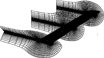
Figure 14.1 Example of the gridding of a helicopter rotor blade using C-type grids on which to solve the Navier-Stokes equations. Source: Grid courtesy of Karthikeyan Duraisamy.

Several types of grid systems are appropriate for analyzing various parts of the helicopter flow problem. Grids are categorized according to their geometric shape, that is, О-, C-, and H-type grids. The O – and C-type grids are often used for analyzing the flows about blades as they can be made to conform to the curved airfoil shape of the blade surface. H-type grids are sometimes used instead, as they allow a compromise between the advantages of a simple Cartesian grid geometry and an ability to refine the grid near the surface of the blade. Overset or chimera grid systems are locally refined grids that are superimposed upon a main (background) grid. These are useful in helping to resolve local flow phenomena without the need to grid the entire flow domain at high resolution. They can also be used to resolve the difficulties in dealing with a domain that is most easily meshed using separate grids that can move relative to each other. Interpolation routines are required to transfer information between the overset grids in the flow solver, and the accuracy of these procedures needs to be carefully controlled to avoid degrading the overall accuracy of the numerical solution. Structured grids such as these, though, can be very labor intensive to create. Unstructured grids, composed of irregularly distributed tetrahedral elements, are increasingly being used because these have the advantage that semi-automatic mesh generation software can be used to create this type of grid around very complex surface geometries.

The numerical technique used to solve the Navier-Stokes equations may be based on either a finite-difference or a finite-volume approach, and numerous algorithms have been developed, each with their own particular advantages. Finite-difference methods approxi­mate the various space derivatives in the equations using expressions based on Taylor series approximations at each node on the computational grid. (A node can be considered as the intersection between grid lines.) Finite volume methods operate on an integral form of the Navier-Stokes equations, derived from Eq. 14.7, and treat the computational domain as a patchwork of cells rather than nodes. The integral of the mass, momentum, and energy within each cell is divided by the cell volume to get an average conserved variable and average fluxes are derived in a similar way by integrating over the boundary of the cell. Although there are many good computational reasons to adopt a finite-volume rather than a finite-difference approach, both approaches are ultimately equivalent in the mathematical sense. However, finite-difference methods can only operate on structured grids, whereas finite-volume methods can be used on both structured and unstructured grids.

Some of the first approaches to solving the Navier-Stokes equations (RANS equations), in this case for a rotor, are described by Agarwal & Deese (1988) and Wake & Sankar (1989). The effect of the rotor wake was computed by means of a vortex method and cou­pled to the Navier-Stokes solution for the blade flow by means of a correction to the AoA along the blades. This is the essence of the so-called loose or “weak” coupling procedure (see page 806). Many variations of this basic approach have followed this. One particu­larly promising modem Navier-Stokes approach for helicopter applications is called the Transonic Unsteady Rotor Navier-Stokes (TURNS) method – see Srinivasan & Baeder and colleagues (1.992,1993). More modem methods use a strong coupling approach where both the rotor and the wake flow are solved simultaneously. In the latest versions of this RANS-type method, a high-order discretization of the governing equations is used to limit the extent of the nonphysical numerical dissipation that is a well-known but very undesir­able feature of finite-difference or finite-volume solutions to the Navier-Stokes equations. Another, similar method thaf has been used for helicopter applications is OVERFLOW, which is based on a general purpose Navier-Stokes code developed by NASA – see Chan et al. (2001) for an overview.

In these approaches, the rotor blades and computational domain are usually enveloped in body conforming grids, an example of which has been shown in Fig. 14.1. Here a rotor blade has been enveloped in a C-type grid to allow good resolution of the flow near the blade surface and in the wake downstream of the blade. Ail types of CFD methods solve the governing fluid dynamic equations to an accuracy that is dependent on the resolution of the grid, and Navier-Stokes calculations require these grids to be created to give extremely fine resolution of the flow near the blades and/or body surfaces (and in the wake downstream) where the viscous stresses are the highest.

Fundamental Governing Equations of Aerodynamics

Documented work in helicopter CFD shows that a wide range of numerical tech­niques have been used to solve a hierarchy of equations governing the flow, these ranging from irrotational, inviscid potential flow approximations, through full-potential, to Euler and Navier-Stokes equations capable of resolving the effects of compressibility and turbu­lence. Each level in the hierarchy brings with it an increasing level of physical modeling capability but also more computational effort A key issue in the use of these types of numerical methods is the definition of an appropriate computational grid surrounding the rotating and nonretating parts of the helicopter on which to solve the governing equations. Other issues include the difficulties in modeling flow turbulence, on both the rotor and the airframe and in the rotor wake, and especially in the powerful tip vortices produced by the blades. Nonphysical numerical diffusion of wake vorticity produces errors in the wake so­lutions and has led to the development of adaptive gridding, overset grids, and other types of vorticity capturing schemes. Until these problems are better solved, however, aerodynamic models based on CFD alone will prove inadequate for helicopter design. The near future will continue to see the development of a range of hybrid models, using the best elements of СГО coupled with other forms of advanced analysis.

Fundamental Governing Equations of Aerodynamics