Category Principles of Helicopter Aerodynamics Second Edition

The International Standard Atmosphere

An important point to remember is that the rotor performance and the performance of the helicopter as a whole is a function of the air density in which it is actually flying. This makes it problematic to predict or compare aircraft performance metrics unless the data are corrected to some standard condition. For example, decreasing density (increasing altitude and/or temperature) will result in a greater power required for the same aircraft gross takeoff weight (GTOW). To remedy this problem, the International Standard Atmosphere (ISA) has been established, which gives the height in a standard atmosphere corresponding to the properties of the air in which the aircraft is flying. The standards1 are defined in Minzner et al. (1959), the ICAO (1964), and NASA (1966), where a standard day at sea level is an air temperature, 7b, of 15°C (59°F, 288.16°K, 518.4°R) with a barometric pressure, po, of

2116.4 lb/ft2 or 101,301 N/m2 or 29.92 in (980 mm) of mercury or 1013.2 millibars.

The International Standard Atmosphere Подпись: (5.1)

The pressure in the atmosphere is a function of altitude (elevation), h, and the air density is a function of both altitude and temperature. The pressure in the standard atmosphere is defined relative to the standard conditions as

where h is in feet, and the density is defined by

Подпись: (5.2)— = a = (1 – 6.876 x 10~6h)4 265.

1 The ICAN standard may be used in many European countries.

The International Standard Atmosphere
Подпись: p
The International Standard Atmosphere
Подпись: (5.8)

While it is the density altitude that affects the performance of the helicopter, the advantage of using pressure altitude is that it is a function of the ambient pressure alone, and the value of hp can be read directly off the altimeter in the aircraft. This is done by setting the value in the altimeter Kohlsman (reference) window to the standard sea level pressure

The International Standard Atmosphere

Altitude

(ft)

Altitude

(m)

Temperature

(°F)

Temperature

(°С)

Density ratio

(p/Po)

Pressure ratio (P/Po)

0

0

59.0

15.2

1.0000

1.0000

1,000

304

55.4

13.2

0.9771

0.9644

2,000

609

51.9

11.2

0.9428

0.9298

3,000

914

48.3

9.3

0.9151

0.8962

4,000

1,219

44.7

7.3

0.8881

0.8637

5,000

1,524

41.2

5.3

0.8617

0.8320

6,000

1,828

37.6

3.3

0.8359

0.8014

7,000

2,133

34.0

1.3

0.8106

0.7716

8,000

2,428

30.4

-0.6

0.7860

0.7428

9,000

2,743

26.9

-2.6

0.7620

0.7128

10,000

3,048

23.3

-4.6

0.7385

0.6877

11,000

3,352

20.1

-6.6

0.7155

0.6614

12,000

3,657

16.52

-8.6

0.6932

0.6360

Table 5.1. Useful Values for the International Standard Atmosphere

Bhp^5-256

)

0.001981 hp5256
288 Л6 /

Подпись: rr = f- Po Подпись: ^ l (T + 273.16) V* 288.16 / (T + 273.16) V Подпись: (5.11)

of po = 29.92 inches or 1,013.2 millibars (equivalent to 2,116.4 lb/ft2 or 101,301 N/m2). Density altitude, however, must be computed from measurements of pressure altitude cor­rected for nonstandard ambient temperature. The density ratio can be obtained from

where the pressure altitude, hp, is in feet and T is in °С or using

p _ 518.4 / 0.001981 hp

~Po ~ (T + 459.4) V 288.16 )

where hp is in feet and T is in °F. Pressure altitude and density altitude are identical if the temperature conforms to standard conditions. As a rule of thumb, density altitude exceeds pressure altitude by about 60 ft per °F (30 ft per °С) that the temperature exceeds the standard value.

The International Standard AtmosphereA convenient table of values for the standard atmosphere is given in Table 5.1. For example, on a standard day the density ratio will be 1.0 at sea level and 0.888 at 4,000 ft. On a very hot day with a pressure (indicated) altitude of 4,000 ft but with an outside air temperature of 30°C (86°F), which corresponds to approximately 23°C or 41°F over standard conditions, the density ratio will be 0.82. This corresponds to a density altitude of approximately 6,400 ft. Performance charts in a helicopter flight manual may be expressed in terms of either pressure altitude or density altitude, although pressure altitude is the more common form. Because the aircraft altimeter will read pressure altitude, a simple altitude conversion chart is provided to the pilot to allow rapid conversions to density altitude for a given ambient temperature, as required.

Aircraft gross takeoff weight – lb

. Helicopter Performance

Dr. Alexander Klemin (1925)

5.1 Introduction

The aerodynamic tools described in the previous chapters can now be used to analyze the basic performance of the helicopter. By the term helicopter performance we mean the estimation of the installed engine power required for a given flight condition, de­termination of maximum level flight speed, evaluation of the ceiling (in and out of ground effect), or the estimation of the endurance or range of the helicopter. Both the momentum and blade element methods will allow for good estimates of total rotor thrust, power, and figure of merit in hover and can be used with confidence to predict overall rotor perfor­mance in forward flight. In addition, the performance of the helicopter during maneuvers, in descending autorotational flight, in flight in or near the vortex ring state, and during flight operations when operating near the ground will be considered in this chapter.

Typical Trim Solution Procedure for Level Flight

Typical Trim Solution Procedure for Level Flight Typical Trim Solution Procedure for Level Flight

In the trim process, the rotor collective and cyclic pitch controls must be adjusted to control the orientation of the rotor to provide trim, control and propulsion requirements. For wind-tunnel trim, the rotor cyclic controls are calculated from a prescribed rotor shaft angle (say, equivalent to Op). In a wind tunnel, the model rotor is controlled by a conventional swashplate and the operator remotely “flies” the model rotor very much in the way of an actual helicopter. However, because the rotor is rigidly attached to a support system, the operator must ensure that large amounts of cyclic flapping do not occur as the wind speed is increased. This is done by constantly controlling the orientation of the swashplate to eliminate cyclic flapping with respect to the rotor shaft. A typical free-flight trim simulation is more complicated because it must satisfy the vehicle equilibrium equations and involves the following steps:

which is valid for p, > 0.1. For lower advance ratios, we should use the more complete expression

СРш = 2y/iJM+X2 + ^ + 4,65+ 2 (a) ^ + XcCtmr’ (4-123)

where the iterative numerical procedures to solve the general inflow equation that have been discussed in Section 2.14.3 can be used to determine X.

3. Calculate the tail rotor thrust from the torque balance using

Подпись: (4.124)ytr _ cQMr r _ cpMr r w cTmr 1t Ctmr h

4.

Typical Trim Solution Procedure for Level Flight Typical Trim Solution Procedure for Level Flight

Calculate the inflow, Xjpp using

5. Calculate the drag and side forces using Eqs. 4.113 and 4.114. For the first iteration, set C^p = Cy^p = 0.

6. Calculate fc, (3s, 0F, and фр.

Typical Trim Solution Procedure for Level Flight

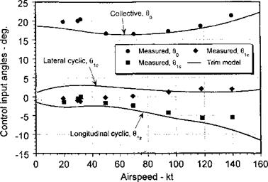
Figure 4.25 Representative variations in collective and cyclic pitch inputs to trim a rotor in forward flight. Propulsive trim calculation. Data source: Ballin (1987). (Calculation courtesy of Rendy Cheng.)

7. Calculate во, 0s, fio, and 6c.

8. Go back to step 3 and recalculate the values.

9. Iterate and monitor the control angles until convergence is achieved.

Representative variations in the control input angles, 6q, 9c, and 9s versus forward speed for a conventional helicopter, as computed from a typical free-flight trim solution, are shown in Fig. 4.25. The results must be considered representative only but are typical of the inputs that would be required on any single rotor helicopter. An example helicopter, which resembles the UH-60, was used for these calculations. Experimental measurements of control angles are also shown, which are taken from Ballin (1987). Remember that as the rotor transitions from hover to forward flight, a primary effect is the dissymmetry in lift between the advancing and retreating blades. The excess of lift on the advancing blade causes the blade to flap upward, reaching a maximum displacement over the front of the disk. Conversely, the reduced dynamic pressure on the retreating blade causes the blade to flap downward over the rear of the disk. The net effect is that the rotor disk naturally wants to tilt back (i. e., a negative longitudinal flapping or Therefore, to prevent this longitudinal

flapping, the cyclic pitch controls must be adjusted to bring the rotor disk back to an orientation that will meet propulsion (to overcome vehicle drag) and control requirements. Notice that the 9s component of cyclic pitch (longitudinal cyclic) controls the longitudinal flapping; thus an increasingly negative value of 9s (of magnitude approximately equal to — file) must be imposed by using forward stick.

The effects of blade coning cause a lateral flapping response. When a blade passes over the front of the disk, the effects of the forward flight velocity cause an increase in AoA because it acts as an upwash. At the rear of the disk, the effects of the free stream cause a decrease in AoA. Therefore, there is a once-per-revolution (1/rev) forcing function gener­ated as a result of blade coning, and the response to this forcing causes a negative lateral disk tilt (to starboard). The amount of lateral tilt is proportional to the rotor coning angle, which in turn depends on inflow for a given rotor thrust. To counteract this effect, a positive value of lateral cyclic (9c) must be applied using left stick. A small additional amount

of lateral cyclic must also be applied to counter the thrust and moments produced by the tail rotor, which will vary with the anti-torque requirements. Also, some lateral cyclic is required to compensate for the nonuniformity of the longitudinal inflow over the rotor disk in forward flight (see Section 3.5.2). Because of these coupled effects, the amount of lateral cyclic required for trim does not show a strong trend in one direction unlike the longitu­dinal cyclic. See Harris (1972) for a systematic study of inflow effects on rotor flapping response.

V~/lld|Jl. Cl ivcvicw

A basic understanding of the dynamic behavior of the rotor blades in response to the changing aerodynamic loads has been the objective of this chapter. The blades have two primary degrees of freedom: flapping and lagging, which take place about either mechanical or virtual hinges near the blade root. A third degree of freedom allows pitch or feathering of the blade, which can be applied in both a collective and cyclic sense. Despite the fact that helicopter blades are relatively flexible, centrifugal effects cause stiffening and the basic physics of the blade dynamics can be explained by assuming them as rigid. In hovering flight the airloads do not vary with azimuth, therefore the blades flap up and lag back with respect to the hub and reach a steady equilibrium position under a simple balance of aerodynamic and centrifugal forces. However, in forward flight the fluctuating airloads cause continuous flapping motion and give rise to aerodynamic, inertial and Coriolis forces on the blades that result in a dynamic behavior with an amplitude and phase response. The flapping hinge allows the effects of the cyclically varying airloads to reach an equilibrium with airloads produced by the blade flapping motion. It has also been shown that the flapping motion is highly damped by the aerodynamic forces so the blades flap and the rotor tilts almost immediately in response to control inputs.

A rotor blade has a flapping natural frequency that is equal to its rotational frequency (or nearly so). Because the rotor is excited by the aerodynamic loads primarily at 1/rev, this means that there is a 90° phase lag between the aerodynamic forcing and the blade flapping response. It has been shown how collective and cyclic pitch can be used to change the magnitude and phasing of the aerodynamic loads over the disk. This is the key to changing the flapping of the rotor and the orientation of the rotor plane, thereby effecting a means of control for the helicopter. The ideas of controlling the orientation of the rotor are formally embodied in a procedure known as “trim.” While there are many forms of numerical solution to the trim problem, the basic procedure is the same: to adjust the control inputs to give resultant forces and moments on the helicopter that will satisfy a specified equilibrium and propulsive force condition. The evaluation of the various forces and moments acting on the helicopter is by no means trivial. However, under certain assumptions and with sufficient labor, many of the results can be obtained analytically in closed form. This allows the identification of the relationships between the solution and various problem parameters and will be useful for many problems related to the preliminary design of the helicopter.

Equations for Free-Flight Trim

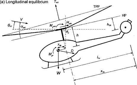
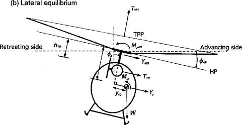
Figure 4.24 shows the forces and moments acting on the helicopter in free-flight. In the treatment of the trim problem, it is useful to decompose each of the components according to its origin. For example, the moment can be written in terms of the contributions from the main rotor (MR), fuselage (F), horizontal tail (HT), vertical tail (VT), tail rotor (TR), and other sources (O) as

M = Mmr + Mp + Мит + Myr + Mjr 4* Mo (4.102)

and similarly for the other force and moment components. The hub plane (HP) is used as the reference plane. The flight path (FP) angle is 6pp. It will be assumed that there is

Equations for Free-Flight Trim

Equations for Free-Flight Trim

Figure 4.24 Forces and moments acting on a helicopter in free-flight. (a) Longitudinal forces and moments, (b) Lateral forces and moments.

no side-slip angle, therefore the fuselage side force (YF) can be assumed negligible. Also, it will be assumed for simplicity that there are no contributions from the horizontal and vertical tails. For vertical force equilibrium

W—Tmr cose? cos фр+D sm6pp—HMR sin0f+YMr sinфр+YjR sin<Pf = 0.

(4.103)

For longitudinal force equilibrium a balance of forces results in

D cos Opp + HMR cos 6F — Tmr sin вр cos фр = 0. (4.104)

For lateral force equilibrium the tail rotor thrust, TPr, must be included to give

Ymr cos фр + TTR cos фр + TMR cos 9F sin фр = 0. (4.105)

For pitching moment equilibrium about the hub

MyMR + MyF — W(xcg cos вр — h sin 0/9 — D cos Gp(h cos 6F + xcg sin 0F) = 0.

(4.106)

For rolling moment equilibrium about the hub

MXMR + MXF – f – TTRhTR + W(h sin Фр – ycg cos фр) = 0. (4.107)

Finally, torque equilibrium about the shaft gives

Qmr — YTRlpR = 0. (4.108)

Using small-angle assumptions, the equilibrium equations can be reduced to the set

W-TMR = 0,

D + HMR — TMR0F = 0,

Y + TTR 4- Тшфр = 0,

Муш + MyF + W(h6p — xcg) — hD = 0,

Mxmr + MXF + W(hфp — ycg) – b TpRhjR = 0,

Qmr — TjrItr = 0.

The rotor thrust is simply the average of the blade lift during one revolution multiplied by the number of blades. Mathematically, this is stated as

дj p2n pR

TMr = ^ / dFzdf. (4.109)

J о Jo

Подпись: CTMR = Подпись: 2 2JT Подпись: drdifr. (4.110)

The thrust coefficient can therefore be written as

Equations for Free-Flight Trim Подпись: во 3 Equations for Free-Flight Trim Подпись: (4.111)
Equations for Free-Flight Trim

Because of the complexity of the expressions for UP, UT, and в, this equation must usually be solved numerically. However, by assuming uniform inflow, that is, X(r, ф) = X = constant, Cd = CdQ, c = constant, and linear blade twist, we can obtain the result for the rotor thrust coefficient analytically. The result can be shown to be

Equations for Free-Flight Trim Equations for Free-Flight Trim

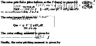
In addition, the rotor torque, side force, drag force, and moments about the respective axes can be computed by a similar process. The rotor drag force (also known as the Я-force) is given by

Подпись: (4-117)Мут ~ ~Ът Jo Jo ydFz C°S ^d

Closed-form expressions for the latter quantities can also be derived.

Equations for Free-Flight Trim Подпись: ҐА 11 ЯЛ

Additional equations may be necessary. For example, two more equations should be added to determine the trim value of main rotor inflow Xmr and tail rotor inflow Xjr. These inflow equations should be solved together with all the other trim equations. For this purpose it is convenient to rewrite them so that all the terms are on one side of the equal sign. Using simple momentum theory for the main rotor (MR) gives

Подпись: кTR — R'TR tan CXTR — Equations for Free-Flight Trim Подпись: = 0, Подпись: (4.119)

where їїmr cos amr = V/ QmrRmr and aMR is the disk AoA, for which setting aMR = a is usually reasonable. For the tail rotor (TR),

Подпись: TR2-і/lijR 4" к

where fijR = V cos cctr/ QtrRtr and cijr is the disk AoA of the tail rotor (this will be zero if there is no side-slip angle).

The vehicle equilibrium equations, along with the inflow equations, can then be written in the form F(X) = 0, where X is a vector of rotor trim unknowns defined as

X = [0o 0c 0s mr ^tr 0F фр]т, (4.120)

Introduction to Rotor Trim

The trim solution involves the calculation of the blade pitch control settings, rotor disk orientation (blade flapping) and overall helicopter orientation for the prescribed flight conditions. Controlling the position of the helicopter in free-flight requires the adjustment of the forces and moments about all three axes. For a conventional helicopter there are three independent controls used for this purpose:

vector, producing both a side force and a rolling moment about the center of gravity of the helicopter. Longitudinal cyclic (0^) imparts a once-per-revolution cyclic pitch change to the blades such that the rotor disk can be tilted fore and aft. Like the lateral cyclic, this changes the orientation of the rotor thrust vector, in this case producing both a longitudinal force and pitching moment. Both lateral and longitudinal cyclic are controlled by the pilot using a cyclic stick (similar to the conventional stick on a fixed-wing aircraft), which is held in the pilot’s right hand.

3. Yaw: This is controlled by using the tail rotor thrust. The pilot has a set of floor mounted pedals, which are operated by the pilot s feet, jusi іікс & ruuuci on u fixed-wing aircraft. By pushing the pedals in the required direction, the collective pitch, 0TR, on the tail rotor is changed, producing a change in tail rotor thrust and, therefore, causing the nose to yaw right or left.

As will be appreciated, there is a considerable amount of crosscoupling of the forces and moments on the helicopter when the pilot applies the controls. The relevant equations describing the behavior of the helicopter are complicated and interdependent, and there is no simple solution to this problem. For example, a change in rotor thrust produced by pulling up on the collective will require a higher power and will create a larger torque reaction on the fuselage. This, in turn, will require a yaw correction to be made to keep the helicopter tracking in a straight line. These and other so-called cross-coupling effects are unavoidable on a helicopter, but much can be done to minimize their effects and reduce the workload for the pilot by appropriate mixing of the control inputs. On early helicopters this was done mechanically, but now these effects can be handled electronically by an on-board flight

r*Ar»trr1 c/ctom vvuuvi oy chwu.

There are two basic types of trim solution that are of interest to helicopter engineers: “propulsive” or “free-flight” trim and “wind-tunnel” trim. Wind-tunnel trim is used when testing model rotors in the wind tunnel and is somewhat different from free-flight trim because only force equations are used. For propulsive trim, the solution simulates the free – flight conditions of the helicopter, and moment equations must be included. For a specified helicopter gross weight, altitude, center of gravity location, forward speed and flight path angle, the trim solution must numerically evaluate the rotor controls, namely the collective pitch angle в o’, the cyclic pitch angles Gc and 9s the rotor disk orientation, which is described by j80, fic and fi]S and the vehicle orientation, which is described by the inertial angles (pitch angle, 6p, roll angle, фр) and the aerodynamic angles (angles of attack, a, and sideslip, fi) and the tail rotor collective pitch, Otr.

There are many possible forms of trim solution, and several levels of approximations and assumptions are used. In all cases, the free-flight trim solution is obtained from a set of vehicle equilibrium equations. These are usually simplified by using small-angle assumptions, although, for some flight conditions, such as turns where the angles are large, such assumptions become increasingly questionable – see Chen & Jeske (1981). Some trim solutions neglect the lateral equilibrium equation and this is justified because a lateral tilt of the rotor disk does not substantially change the rotor or fuselage aerodynamics. The trim solution can be approached from two perspectives. One approach is to use the blade element theory with certain assumptions for the wake inflow to calculate analytic results for the blade flapping and control angles. This gives a good first estimate of the rotor trim state. Another approach is to use a less restrictive solution for the blade aerodynamics (which may include nonuniform inflow and nonlinear aerodynamics) and to calculate the rotor trim state numerically – see Section 10.7.6. In either case, an iterative approach is required.

Semi-Rigid or Hingeless Rotors

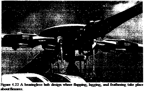
In the semi-rigid type of hub design, the flap and lag hinges are replaced by flexures (Fig. 4.22), which are normally built out of advanced composite materials. This eliminates the complexity, weight, and maintenance that is associated with the use of mechanical hinges and bearings. There are many different types of semi-rigid or hingeless hub designs. If the feathering bearing is also replaced by a flexible element, it is called a bearingless hub design.

Подпись: Figure 4.22 A bearingless hub design where flapping, lagging, and feathering take place about flexures.

The analysis of the semi-rigid blade proceeds by assuming that the flexure provides an equivalent spring stiffness kp at an equivalent hinge offset e. In this case, the equation of motion becomes

I m(y – eRffidy +’ / m(y – eR)p£l2ydy + kp(fi – fp) — / Fz(y – eR)dy, JeR JeR JeR

(4.97)

where all the symbols have their usual meaning and ftp is the pre-cone angle. This pre­cone angle is designed into the hub and blade to reduce the steady flapping moments about the hinge (like the underslung teetering design) and typically would be about 2-3°. The foregoing equation can be written in conventional form as

2

$ + Vpf = у Mp + (4.98)

Подпись: vp Подпись: л Ъе aft н— + -4, 2 Q2 Подпись: (4.99)

where coq is the nonrotating flapping frequency as given by coq = у/kp/Ip. The natural frequency of flapping is

where it has been assumed that Ip « lb. Notice that the flapping frequency is now affected by both the CF forces and the elastic bending stiffness of the hub. If coq = 0, then the result reduces to that for an articulated rotor.

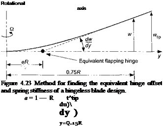
The equivalent hinge offset and flap stiffness can be determined approximately by com­paring the deflected slope of the blade at the root to a point further out on the blade (normally 75% radius), as shown in Fig. 4,23. The majority of the curvature is in the hub region at

Semi-Rigid or Hingeless Rotors Подпись: (4.100)

the flexure and the remainder of the blade is essentially straight. The equivalent offset e is given by

кв = iBn[18] [19] (

Подпись: 3e^ 2 / ' Подпись: (4.101)

and the effective spring stiffness is

A similar approach can be used for the lagging direction. This means that the analysis of the hingeless rotor design can proceed using all the same methods of analysis used for the articulated rotor, but with a corrected effective hinge offset and flapping frequency.

Coupled Flap-Lag Motion

It will be apparent from the foregoing that, in practice, the blade flapping and lead-lag motion are coupled. Now consider the analysis of the problem where the blade simultaneously undergoes two types of motion with both flapping and lead-lagging about their respective hinges. This type of model is a good representation of a blade with a high torsional stiffness. For simplicity, it will be assumed that the flapping and lead-lagging hinges are coincident. In this case, note that the flapping and lead-lag motions are coupled as

a result of Coriolis and aerodynamic forces. Coriolis effects introduce an important coupling between blade flapping or out-of-plane motion and lead-lag or in-plane motion. The Coriolis effect is an additional inertial force, first described by Gustave-Gaspard Coriolis in 1835. Coriolis showed that in a rotating frame of reference, an inertial force must be included into the general equations of motion. On a rotor, Coriolis forces will appear whenever there is a radial lengthening or shortening of the blade about the rotational axis, which will be a result of blade flapping or bending. Coriolis effects produce forces in the plane of rotation of the rotor.

A more complete description of the various forces acting on the rotor can now be obtained. For the flapping motion, the forces acting on the blade element are as follows:

Подпись: (4.87)
Coupled Flap-Lag Motion

where the lagging frequency can be found from

Coupled Flap-Lag Motion
and the coning angle now becomes

Coupled Flap-Lag Motion

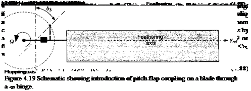
which relative to the case without pitch-flap coupling is reduced for a given collective pitch. On tail rotors, the <$3 angle is close to 45°, which makes the effect significant. Two examples of tail rotors sporting a 83 hinge are shown in Fig. 4.20.

4.13.1 Teetering Rotor

The teetering (or seesaw) rotor design has already been mentioned; the two inter­connected blades form a single structure and have a flapping hinge located on the shaft axis. The teetering design uses no independent flap or lead-lag hinges. An example is shown in Fig. 4.20(a) and is illustrated schematically in Fig. 4.21. The blades may have a built-in precone angle, /Sp, which reduces lift-induced steady bending loads. A 83 angle may be included, which as previously mentioned, reduces cyclic flapping and Coriolis effects. A separate pitch or feathering bearing on each blade allows for cyclic and collective pitch capability.

The dynamic flapping motion of the teetering rotor is obtained by considering simulta­neously the equilibrium of forces on both blades. Consider the flapping moments about the

Rotational

Coupled Flap-Lag Motion1 Teeter hinge

—sc

Figure 4.21 A teetering rotor design has two interconnected blades that behave as a single rotating system.

teeter hinge. Each blade has a contribution to the moment, which is equivalent to twice the moment produced by any one blade. This means that

and for the other blade, which is located at + л, the flapping motion is

OO

02(VO = – 0i = 0o + lA*c cos n№ + + 0И* sinn(f + я)]. (4.94)

n—1

This latter equation may be written as

OO

= 2PP – fa =0o + ^(-1)" (0nc cos nxjs + fins sin nrjr). (4.95)

n= і

Substituting Eq. 4.93 into Eq. 4.95 and equating trigonometric coefficients gives

OO

02(VO = 0p + (Pnc cos nФ + 0»J sinnf). (4.96)

n odd

This means that for the teetering rotor the coning angle is equal to the precone angle fip and also that only the odd harmonics of flapping are present; the even harmonics cancel and the effects are reacted as structural stresses internal to the rotor hub. Because the harmonics of n > 3 are small they may be neglected. Only the first harmonics of flapping remain, which control the orientation of the rotor tip path plane. This means that all the solutions obtained for the articulated rotor also apply to the teetering rotor, but only if they are referred to the

/4*. Mlm

олій ui no l^aui&iuig ui iyr. r.

Dynamics of a Lagging Blade with a Hinge Offset

The blade is assumed to be rigid and undergoes a simple lagging in the plane of rotation about a hinge located at a distance eR from the rotational axis. The various forces acting on the blade are now:

1. The inertia force mx dy = m(y — eR)£ dy, acting at a distance (y — eR) about the lag hinge.

2. The centrifugal force mO,2y dy acting at a distance eRx/y from the rotational axis, where x = (y — eR)/i;.

3. The aerodynamic drag force D dy acting at a distance (y — eR) from the hinge axis.

Taking moments about the lag hinge gives

pR pR gft pR

I m(y — eR)2£ dy + I m£22y(y — eR)—£ dy — I D(y — eR)dy = 0. JeR JeR У JeR

(А 11Л

Подпись: i(y - eR)2 dy = IK.
Подпись: f
Подпись: (4.78)

The mass moment of inertia 1^ about the lag hinge is

Подпись: (4.79)Therefore, the equation of motion for lagging about the lead-lag hinge can be written as

h(i + ^) = ^[RDiy-eR)dy,

where is the nondimensional lag frequency in terms of the rotational speed, as determined from

which is shown graphically in Fig. 4.17. Because the centrifugal restoring moment about the lag hinge is much smaller than in flapping, the corresponding uncoupled natural frequency of the lag motion is much smaller. For articulated rotors, the uncoupled rotating lag frequency varies from about 0.2 to 0.3Q (see also Question 4.9). For hingeless designs, the value of is much higher, typically from 0.6 to 0.8£2.

Notice that the lag motion of the blade is lightly damped. Besides the fact that the lead – lag displacements about the hinge are small, they only produce aerodynamic forces through changes in velocity and dynamic pressure normal to the leading edge of the blade. This has a much smaller effect than the aerodynamic forces produced by changes in AoA induced

hv ЫяНр. Яяппіпа motion Alert thp Нгяа fnrrpc ar*tina rtn the* ЫяНр. с ягй almnct twn rtrH^rc ~**«rr***& 4,44 W4V ~**~*~~ V4A4A1VWV fcTTV V4V4WU

of magnitude less than the lift forces. Therefore, because of the low inherent damping it is

found that the blade lag motion is very susceptible to driving various types of aeroelastic

and aeromechanical instabilities on the rotor.

One important example of an aeromechanical instability associated with blade lag motion

is ground resonance, where the blade lag motion and the in-plane motion of the fuselage

become coupled to produce a catastrophic aeromechanical instability. Ground resonance

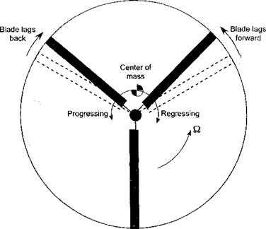
is associated with the out of pattern in-plane motion of the blades (see Fig. 4.18) and a

coupling with the dynamics of the undercarriage and wheels of the helicopter when on the

ground. When the motion of the center of gravity is in the same direction of rotor rotation it is

Dynamics of a Lagging Blade with a Hinge Offset

Figure 4.18 Ground resonance is a potentially catastrophic aeromechanical instability of the rotor resulting from an out-of-pattem in-plane lead-lag motion of the blades and its coupling with airframe motion on its landing gear.

called the progressive lag mode, and when in the opposite direction it is called the regressive lag mode. The problem of ground resonance occurs when the frequency of the regressive lag mode corresponds to an airframe frequency. This causes the net center of gravity of the rotor system to spiral outward away from the rotor hub, initially resulting in a severe shaking of the machine and quickly leading to a catastrophic resonance. “Sympathetic” pilot inputs through the flight controls can provide the initial excitation to the rotor system, although taxiing the machine over rough ground can also be a culprit. A related problem is called air resonance, which occurs in flight when the regressive lag mode couples with the fuselage roll and pitch motions, and this too can also be disastrous. This is the reason why most helicopter rotors have mechanical lag dampers, which provide artificial damping to suppress the occurrence of aeromechanical phenomena. If the lag frequency is larger than the rotational frequency (i. e., for a stiff in-plane rotor blade), then there is no possibility of ground or air resonance instability. Coleman & Feingold (1958) developed the first mathematical theory to predict and cure the problem of ground resonance, although even here several aerodynamic approximations are involved. A good summary of the theory of ground resonance is also given by Bramwell (1976) and Johnson (1980).

Review of Rotor Reference Axes

There are several physical planes that can be used to describe the equations of motion of the rotor blades. These reference planes or axes systems have evolved as a matter of convenience, and each has advantages over others for certain types of analysis. However,

Review of Rotor Reference Axes

Figure 4.13 Hub of a coaxial rotor system showing the high level of mechanical complexity.

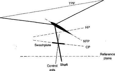
it is always possible to transform an analysis from one reference axis to another, as required. Figure 4.14 schematically shows the various reference planes and axes that are often used in helicopter analyses. These planes are:

1. Hub Plane (HP): The rotor hub plane is perpendicular to the rotor shaft. In the HP, an observer would see both blade flannina and feathering initr. h changes) during forward flight. While this plane is the most complicated for analysis of the rotor, it has the advantage of being linked to a physical part of the aircraft. The HP is often used for blade dynamic and flight dynamic analyses.

2. No Feathering Plane (NFP): This plane was first introduced by Gessow & Myers (1952). The NFP is a plane where an observer sees no variation in cyclic pitch, that is both вс and 6s are zero. However, the observer will still see a cyclic variation in blade flapping angle. Normally, this plane is used for performance analyses.

3. Tip Path Plane (TPP): This is the plane whose boundary is described by the blade tips. Therefore, an observer will see no variation in flapping, that is, both fc and

Review of Rotor Reference Axes

Review of Rotor Reference Axes

Figure 4.14 Schematic of rotor reference axes and planes.


fiis will be zero. This plane is commonly used for aerodynamic analyses, such as rotor inflow or other wake models.

4. Control Plane (CP): This plane represents the commanded cyclic pitch plane and is sometimes known as the swashplate plane.

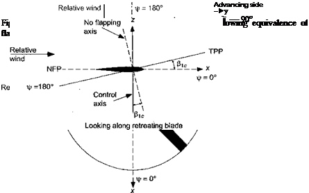
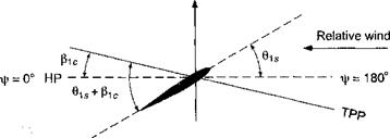
Consider now a rotor in forward flight and assume that the rotor has a simple flapping motion with only fic – that is, the rotor tilts forward by the amount fic as shown in Fig. 4.15. Notice that the relative amount of blade flapping versus feathering depends on the axis system to which the blade motion is being referenced. At fr = 0° we see that with respect to the NFP the blade flapping is full up, but the blade pitch is neutral (zero in this case). At ifr = 90°, with respect to the NFP the blade flapping is now zero, again with the pitch being neutral. However, at this azimuth the blade pitch is a maximum with respect to the TPP.

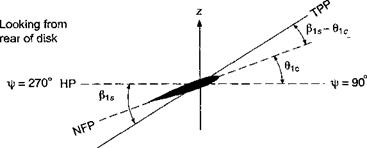
Now consider a more general case where the disk is tilted both forward and to the left. Again, as shown by Fig. 4.16, we see that the amount of blade feathering versus flapping depends on the axis system used to view the blade motion. Therefore, in light of this and the previous example, it is apparent that the amount of blade pitch (feathering) with respect to the TPP is equal to the amount of blade flapping with respect to the NFP. Fore and aft (longitudinal) flapping or fi[c with respect to the NFP is equivalent to lateral feathering (pitch) with respect to the TPP. Therefore, there is an equivalence of flapping and feathering motion. Strictly speaking, this equivalence is only true for a teetering type of rotor (where the flapping hinge is exactly at the rotational axis), but the equivalence is strong for all types of helicopter rotors. The results of this example are summarized in Table 4.1.

In the transformation from one plane to another, it will be apparent that

Подпись: (4.74)file + — constant — (^ic)nfp — (^ь)трр •

Also, we have that

Review of Rotor Reference Axes

Using the above relationships, it is possible to transfer any analysis from one reference system to another, that is, from the TPP to the NFP or vice versa. For example, the angles of attack in the TPP are related to those in the NFP by

(ог)трр = («)npp — (fiic + 0is). (4.76)

Table 4.1. Summary of Blade Motion with Respect to NFP and TPP

f

With respect to NFP

With respect to TPP

Flapping = max up

Pitch = zero

о

о

Os

Flapping = zero

Pitch = max

180°

Flapping = max down

Pitch = zero

270°

Flapping = zero

Pitch = min

Looking along


a?


Review of Rotor Reference Axes

Figure 4.16 General case of rotor blade undergoing flapping and pitching (feathering).


Review of Rotor Reference Axes

Blade Feathering and the Swashplate

The blade pitch (or feathering) motion can be described as the Fourier series 9(r, ф) — #twr + Oq + 9c cos ф + 0s sin ф

Подпись: (4.73)H—– + One cos пф + 0ns sin пф + • • •,

where r is the nondimensional radial position on the blade. Blade-pitch motion comes from two sources, namely

1. Commanded input from the helicopter control system. This is done by means of a swashplate, the orientation of which is controlled by the pilot. The control inputs produced by the swashplate consist of the collective pitch Bo and the first harmonics of the Fourier series: the lateral cyclic Bic and the longitudinal cyclic Bs. The collective pitch controls the average blade pitch angle and, therefore, the blade lift and average total rotor thrust. The cyclic pitch controls the orientation or tilt of the rotor disk and so the direction of the rotor thrust vector.

2. Elastic deformations (twist) of the blade and control system. The elastic (torsional) deformations of the blade, and although small, they are significant. However, these can be neglected at the present level of analysis.

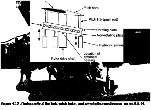
The swashplate is the key to effecting pitch control to the rotor blades, for which a photo is shown in Fig. 4.10 and a schematic in Fig. 4.11. The swashplate has rotating and nonrotating disks concentric with the rotor shaft. A set of bearings between the two disks allows the upper disk to rotate with the rotor while the lower is nonrotating. Both disks can be slid up and down the shaft in response to collective inputs and the swashplate can also be tilted to an arbitrary orientation in response to cyclic inputs from the pilot’s controls. A minimum of three pushrods or actuators are required to position the swashplate relative to the rotor shaft, which is connected (either mechanically or hydraulically) to the flight control system. The upper swashplate has a set of lugs that are connected to the blades, with one lug for each blade. The blade pitch motion itself is induced about a pitch or feathering bearing. A pitch horn is attached to the blade outboard of the pitch bearing. A pitch link is attached to the pitch horn and the upper (rotating) part of the swashplate in such a way that as the upper plate rotates, the vertical displacement of the pitch link produces blade pitch motion. The novel part of the helicopter swashplate is the ability to tilt the plate to an arbitrary orientation, which requires a gimbal or spherical bearing between the swashplate and the rotor shaft. This allows a first harmonic blade-pitch input with any phase angle. The earliest swashplate mechanisms for helicopter applications are documented in patents by Crocco in 1906, Yurev in 1910, and Hafner in 1922. See Prouty & Curtiss (2003) for a good review of other helicopter rotor control systems, including the swashplate.

Blade Feathering and the Swashplate

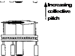
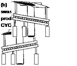
As shown in Fig. 4.12, the vertical motion of the swashplate results in a vertical motion of the pitch link and a collective pitch change to the blades. This either increases or decreases the rotor thrust. The fore and aft tilt of the swashplate translates into a once-per-revolution cyclic pitch on each rotor blade. This produces a once-per-revolution aerodynamic forcing, which causes the rotor blades to flap and the rotor to precess to a new orientation in space, thereby tilting the thrust vector. The system is really fundamentally very simple; an aerodynamic forcing is applied at or close to the natural frequency of the flapping blade and the blades respond so that a unit of cyclic pitch input results in (almost) a unit of flapping response.

Blade Feathering and the Swashplate Blade Feathering and the Swashplate Blade Feathering and the Swashplate

(a) Vertical movement of swashplate
introduces COLLECTIVE pitch.

Figure 4.12 The movements of the swashplate result in changes in blade pitch, (a) Col­lective pitch, (b) Cyclic pitch.

Notice that for a centrally hinged rotor system, the term 9c controls the lateral orientation of the rotor disk and 9s controls the longitudinal orientation. Remember that for a rotor with a centrally located flapping hinge there is an exact 90° force-displacement phase-lag. In the case of pure 9c (cosine) cyclic motion, the maximum applied aerodynamic force occurs at i/r = 0° and so the maximum flapping displacement occurs 90° later at = 90°. Therefore, the application of a 9c pitch displacement causes the rotor to tilt laterally to the left, which is equivalent to a f}s flapping motion and, therefore, this is called lateral cyclic. By a similar argument, the application of a 9s pitch displacement causes the disk to tilt back longitudinally, which is equivalent to a — f3c flapping displacement, and this is called longitudinal cyclic.

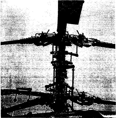
For a contrarotating coaxial rotor system, both rotors must be tilted. Therefore, the pitch angles of both sets of rotors must be connected together through two swashplates so that they tilt in unison. Figure 4.13 gives some idea of the mechanical complexity of the control linkages to do this. Nevertheless, the different aerodynamic environments found on both rotors results in considerable differential flapping. This requires significant spacing between the rotors to ensure that the blades do not collide. The much larger rotor mast and exposed rotor flight control linkages, therefore, result in a high parasitic drag in forward flight. This is one major disadvantage of the coaxial rotor configuration.