Category Principles of Helicopter Aerodynamics Second Edition

Dynamics of Blade Flapping with a Hinge Offset

The analysis of a blade with a hinge offset is similar to the foregoing, but there are some important quantifiable differences. The blade is assumed to be rigid and hinged at a distance eR from the rotational axis. The forces acting on an element of the blade are as follows:

1. Inertia force m(y — eR)0dy acting at a distance (y — eR) from the hinge.

2. Centrifugal force myQ,2 dy acting at a distance (y — eR)0 from the hinge.

3. Aerodynamic lift forces L dy acting at a distance (y — eR) from the hinge.

Dynamics of Blade Flapping with a Hinge Offset

Taking moments about the flapping hinge gives the equation of motion

In this case, the mass moment of inertia about the flapping hinge is

Подпись:Подпись:h

so that the flaDDine eauation becomes

[.. 0( eR fRm{y — eR)dy ) CR

/*|l + fl2(l + " eR h——————— —Jfi = J L(y — eR)dy. (4.63)

Dividing through by Q2 gives

Подпись: (4.64)h(*P 4- v2pp = ^ J L(y – eR)dy,

where vp is the nondimensional flapping frequency in terms of the rotational speed, that is,

fR

eR I m(y — eR)dy

= 1 + JeR,————————- . (4.65)

lb

Dynamics of Blade Flapping with a Hinge Offset Подпись: (4.66)

Again, the physical analogy with a spring-mass-damper system can be drawn. Eval­uation of Eq. 4.65 shows that the undamped natural frequency of the uniform system is now

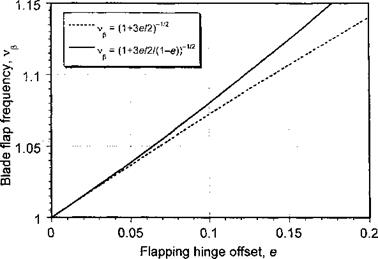
the proof of which is the basis for Question 4.1. The behavior is shown in Fig. 4.9. Typically, the value of e varies from 4 to 6% for an articulated blade (although higher for hingeless

Dynamics of Blade Flapping with a Hinge Offset

Figure 4.9 The blade flapping frequency varies with the hinge offset.


or semi-rigid rotors), so that the natural frequency of the rotor is only slightly greater than £2 or 1/rev. This also means that the phase lag between the forcing and the rotor flapping response must be less than 90° and the flapping displacements also now depend on aerodynamic damping. In this case, the flapping equation is

? + = УЩ, (4.67)

where vp is the rotating flapping frequency in terms of rotational speed. (Remember that vp = 1 for a hinge at the rotational axis.) Therefore, in hover the flapping response to cyclic pitch inputs is given by

А«(^-1) + Аа| = |е1с. (4.68)

Pu(v2f-l)-fiicj = jeu – (4.69)

Dynamics of Blade Flapping with a Hinge Offset Подпись: (4.70)

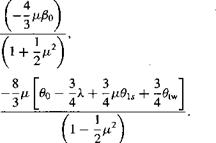
This gives for the longitudinal flapping angle

Dynamics of Blade Flapping with a Hinge Offset Подпись: (4.71)

and for the lateral flapping angle

In this case, the forcing frequency (1/rev) is less than the natural flapping frequency (off resonance condition) and it can be shown that the phase lag, ф, will be less than 90° as given by

Dynamics of Blade Flapping with a Hinge Offset(4.72)

which is a result considered in Question 4.7. For hingeless rotors, which have a relatively

high hi nap offset thp. пЬяяр. Іяа is flhnnt 7S—80°

О О ‘ — о ” ■’ ‘ ~ ‘ “ ’

Lateral Flapping Angle

The coefficient fas represents the amplitude of the pure sine motion (see Fig. 4.8). This represents the lateral or left-right tilt of the tip path plane. In addition to the natural tendency for the disk to tilt back with a change in forward flight speed, the disk also has a tendency to tilt laterally to the right. This effect arises because of blade flapping displacement (coning). For the coned rotor, the blade AoA is decreased when the blade is at тД = 0° and increased when у/ — 180°. Again, another source of periodic forcing is produced, but now this is phased 90° out of phase compared to the effect discussed previously. However, because of the 90° force-displacement lag of blade, in this case it results in a lateral tilt of the rotor disk to the right when viewed from behind (i. e., a — fas motion). Notice that in the hypothetical case with no coning, the blades see the same increase in AoA at i/r = 0° and 180° and there will be no lateral tilt.

4.6.2 Higher Harmonics of Blade Flapping

The coefficients @2о fas, and so on, represent the amplitudes of the higher harmon­ics of the blade motion. In practice, these are found to be very small and of no substantial significance but appear as a slight warping or wobbling of the rotor tip path plane. For

(a) Pure lateral tilt (no coning) (b) Lateral tilt (with coning)

Lateral Flapping Angle

Figure 4.8 Pure lateral flapping of the rotor, with positive displacements shown.

rotor trim and performance evaluation it is considered acceptable engineering practice to neglect all harmonics above the first. However, the effects of higher harmonic flapping on the vibration and aeroelastic stability characteristics of the rotor are important.

Longitudinal Flapping Angle

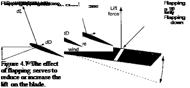
The coefficient 0lc represents the amplitude of the pure cosine flapping motion (Fig. 4.6). This represents a longitudinal or fore aft tilt of the rotor tip path plane. In forward flight, the rotor disk has a natural tendency to tilt back (longitudinally) because of the dissymmetry in lift produced between the advancing and retreating sides of the disk. As a result of the higher dynamic pressure on the advancing side of the disk, the blade lift is increased over that obtained at if = 0° and j/ = 180°. Therefore, as the blade rotates into the advancing side of the disk, the excess lift causes the blade to flap upward, which decreases its lift. This behavior is shown more clearly in Fig. 4.7.

For a single degree-of-freedom linear, time-invariant system excited at its natural frequency, there will always be a phase lag of 90° between the input and the output.

Over the front of the disk the dynamic pressure reduces progressively and the blade reaches a maximum displacement with /3 = 0 at i/r = 180°. As the blade rotates into the retreating side of the rotor disk, the deficiency in dynamic pressure causes the blade to flap downward. This downward flapping motion increases the AoA at the blade element, which tends to increase blade lift over the lift that would have been obtained without flapping motion. This upward and downward flapping of the blade tends to reduce and increase the AoA at the blade elements by an amount

Подпись: r + pПодпись: (4.60)Longitudinal Flapping Angle
Aa(y, p) = — tan-1 (——– ——— ) = — tan-

Longitudinal Flapping Angle

Qy + pQRj

For example, as a result of the flapping upward ф > 0), the blade lift tends to decrease relative to the lift that would have been produced without a flapping hinge. Conversely, for flapping downward, the blade lift tends to increase relative to the lift that would be produced without the flapping hinge.

The upshot of all this flapping motion is that the rotor blades reach an equilibrium con­dition again when the local changes in AoA and aerodynamic loads as a result of blade flapping become sufficient to compensate for local changes in the airloads resulting from variations in dynamic pressure between the advancing and retreating sides of the disk. For the situation described previously, in the final equilibrium condition the disk will be tilted back longitudinally with respect to the hub (i. e., a —fc flapping motion). Remember that the forcing function in this case is phased such that the maximum aerodynamic force occurs at fr = 90°, but because of the dynamic behavior of the rotor blade, the maxi­mum flapping displacement occurs ж/2 or 90° later at if/ = 180°. This is of fundamental importance because it allows an understanding of what happens to the rotor flapping un­der the action of aerodynamic loads that are phased differently with respect to the rotor azimuth.

Physical Description of Blade Flapping

The basic physics of blade flapping are relatively elementary, although on an actual helicopter during flight, the combined harmonics of the flapping displacements result in a more complicated blade motion. To this end, it is convenient to explain the net blade motion in terms of the contributing elements. This is the approach followed by Gessow & Myers (1952).

4.6.1 Coning Angle

The coefficient & is the average or mean part of the flapping motion that is indepen­dent of time or blade azimuth, fs. In hovering flight, — fio, which, as mentioned previ­

ously, is called the coning angle. The presence of a coning angle has been pointed out to be the angle that results from the moment balance about the flapping hinge as a result of the cen­trifugal and aerodynamic forces. Because the centrifugal loads remain constant for a given rotor speed, the coning angle vanes with both the magnitude and distribution of lift across the blade. For example, a higher gross weight of the helicopter requires a higher blade lift to hover, which tends to increase the aerodynamic moment about the hinge, resulting in a higher blade coning angle. Also, it is already known from the previous discussion in Chapter 3 that the inflow velocity has an effect on the blade spanwise loading. As the magnitude of the inflow increases, for a given overall total rotor thrust the blade must become more highly lift loaded toward the tips. This produces a higher aerodynamic moment about the hinge and, therefore, a higher coning angle. Because the time-averaged inflow (induced velocity) through the rotor disk changes with forward speed, the rotor coning angle will mimic the variation in mean inflow through the disk with forward speed, as discussed in Section 2.14.6.

Equation of Motion for a Flapping Blade

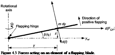
In hovering flight, the solution for f$ is a constant (= fio) independent of Jr and this angle is called the coning angle. Under forward flight conditions as a result of the cyclically (azimuthally) varying airloads, the blade flaps up and down in a periodic manner with respect to azimuth. Consider Fig. 4,5, which shows the line of action of the aerodynamic forces, the centrifugal forces, and the inertial forces acting on a small element of the blade span. Define the moment to be positive in a direction such as to reduce /3. The centrifugal moment about the hinge is

d{McF) = (mdy)y2Q2fi = my2Q,2dy.

(4.24)

The inertial moment about the hinge is

d(I) — (mdy)y2$ = my2$ dy

(4.25)

and the aerodynamic moment about the hinge is

d(Mp) = – Ly dy,

(4.26)

where the sign of the latter term is noted. It will be assumed that there is no hinge offset, that is, e = 0. Therefore, the equation of motion can be derived by summing the moments about the flap hinge giving

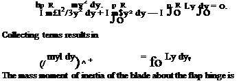
nR pR pR

/ d(McF) + / d{l) + / d(Mp) = 0. (4.27)

Jo Jo Jo

Подпись: Figure 4.5 Forces acting on an element of a flapping blade.

Ldy

Equation of Motion for a Flapping Blade Equation of Motion for a Flapping Blade

Introducing the relevant expressions for d(McF), d(I), and d(Mp) gives

Thus the equation of flapping motion in Eq. 4.29 can be written as

Подпись:fR

Ib’P + IbQ1P = / Lydy.

Jo

Equation of Motion for a Flapping Blade Equation of Motion for a Flapping Blade

Noting that fr = Qt results in the following transformations

or in short-hand notation simply as

Подпись: (4.34)P + P = TT77 f Ly dy

Now, consider the aerodynamic forces. At any blade element of chord c at a radial distance у from the rotational axis it can be readily shown using the blade element theory (Section 3.5) that with uniform inflow the aerodynamic force per unit length is

Подпись: (4.35)

Подпись: I Ly dy = j* У Q Qy = cq. *(«-£-f). Подпись: dy Подпись: (4.36)

L = рЩсС, = dVcC., (в – g – £) so the aerodynamic moment about the hinge will be

The Lock number is defined as

Подпись: (4.37)Подпись: Y =pCiacR4

h

which can be viewed as a measure of the ratio of aerodynamic forces to inertial forces. For a typical helicopter rotor, the value of the Lock number varies from 5 to 10. Notice, however, that its value depends on the density of the air and so will be affected by changes

in density altitude (see Section 5.2). The equation governing the behavior of the flapping blade becomes

Подпись:P + P

Подпись: P + Подпись: 4 Xi Подпись: (4.39)

which on rearrangement gives

This is the flapping equation for a centrally hinged blade, that is, one that is hinged at the rotational axis with e = 0. A more general form is to leave the aerodynamic force (moment) on the right-hand side unintegrated, in which case

Подпись:P + fi = yMp,

Equation of Motion for a Flapping Blade Подпись: (4.41)

where

Notice the similarity of Eq. 4.40 with the equation of motion of a single degree-of – freedom spring-mass-damper system, that is, m’x + cx + kx — F, where x is the dis­placement, m is the mass, c is the damping, and к is the spring stiffness. This system has an undamped natural frequency of con = sjkjm. Therefore, by analogy with Eq. 4.40 the undamped natural frequency of the flapping blade about a hinge located at the rotational axis is once per revolution (1/rev) or wn — £2 rad/s.

Consider first the case where the rotor operates in a vacuum, in which case there are no aerodynamic forces present. The flapping equation reduces to

Подпись:Подпись: (4.43)fi+fi = o.

It is easy to show that this equation has the general solution

fi = fic COS j/ + fiis sin т/f,

where fic and fis are arbitrary coefficients. Thus, in the absence of aerodynamic forces, the rotor takes up an arbitrary orientation in inertial space. In effect, the rotor acts like a gyroscope. The introduction of aerodynamic forces produces an aerodynamic flapping moment about the hinge, which causes the rotor to precess to a new orientation until the aerodynamic damping (which is contained inside the Mp term) causes equilibrium to be obtained once again.

In forward flight, the aerodynamic forces provide the forcing to the flapping blade at multiples of the rotor frequency. This aerodynamic excitation is primarily at 1/rev. The blade flapping motion with respect to the rotor hub can be represented as an infinite Fourier series of the form

p([r) = fio + file COS ir + fils sin f + fi2c COS 2f + fi2s sin 2f л

CO

Подпись: (4.44)= Po+^2 (ft™cos n^+p™ sin n^ ’

/2-І

Equation of Motion for a Flapping Blade
Подпись: (4.47)
Подпись: A.

where the time scale has been nondimensionalized with respect to rotor time such that the dimensionless period is 2n radians. The Fourier coefficients may be evaluated from the flapping displacements using

2 n

pin

/ P dJf, Jo

(4.45)

fine = —

T.

p2n

I P cos пф dф, Jo

(4.46)

pciacR4Q2

= 4′

2 Ja

Подпись: MB = Подпись: 1 Equation of Motion for a Flapping Blade Подпись: (UT QR Подпись: dr. Equation of Motion for a Flapping Blade

Assuming uniform inflow and linearly twisted hlades, we can evaluate the aerodynamic flapping moment about the hinge analytically using the blade element theory where

Подпись: A. I  + Y sin f 6 4

Подпись: * -p Equation of Motion for a Flapping Blade Подпись: ftp, COS l/r Подпись: (4.50)
Equation of Motion for a Flapping Blade

+ 0tw ( 77: + ~r sin Ф + ~r sin2 1If 10 4 6

and this result can then be substituted into Eq. 4.40 to compute fi.

Some interesting characteristics of the resulting flapping equation are as follows:

1. In forward flight, that is, when p ф 0, the equation has periodic coefficients. This does not allow an analytical closed-form solution of the flapping equation.

2. The flap damping term, which is the coefficient associated with the ft term in Eq. 4.50 for Mp, is

Y ( 4 .

— I 1 4- —11 cin tlr I

s Vі ‘ з—;’

which is of aerodynamic origin (all the terms multiplied by the Lock number у come from the aerodynamics) and is usually very high. For the case of hover and for the natural frequency of 1/rev, the corresponding damping ratio is у j 16. For a Lock number у = 8 this means that the damping is 50% of the critical value; thus the blade flapping motion is stable and well damped.

3. Finally, notice that the flapping equation has been derived with respect to the plane defined by the hub of the rotor, and so both the flap angle fi and the pitch control angle в will generally be functions of the azimuth angle ф.

The general flapping equation of motion cannot be solved analytically in closed form for the general case of p, ф 0. Therefore, two options present themselves:

Подпись:Подпись: 2.Solve the equation numerically. The equation can be integrated for given values of collective pitch 6q, lateral cyclic 6c, longitudinal cyclic 6s, and inflow A,. The selection of the initial conditions for the flapping is not very important because even extreme initial conditions will simply cause a numerical transient that will disappear after a few numerical iterations because of the high damping present in the blade flapping motion. The main problem with the numerical solution is that

Подпись: it ПАС nnf rrri M Ла oni7 mn rrlkf mi-л Ілліи th a K1 nda flonnmrt гаоїллига IP UT; it uv/t/o nut pi vj v tut cm j moigiiL III.LV/ iiv/w Li IV/ uictviV/ napping і v/opv/nav/ io cniV/V/LV/Vi и у

the various rotor geometry parameters and operational flight conditions.

Find a periodic solution. In this case the problem is to find a steady-state, periodic solution, in the form of a Fourier series. Obviously this solution is not adequate for transient situations such as during a maneuver, but it allows the identification of the relationships between the flapping response and the various problem parameters.

Assuming the solution for the blade flapping motion to be given by the first harmonics only, that is,

P(f) = Po + file cos if/ + Pu sin if (4.51)

Equation of Motion for a Flapping Blade Подпись: 5 Подпись: (4.52)

and harmonically matching constant and periodic (sine and cosine) terms on both sides of the derived flapping equation gives

Подпись: $tw To Подпись: іПодпись: 2Подпись: F „ A' + бву~бПодпись: Pi s — OleПодпись: Pic + в8Equation of Motion for a Flapping Blade(4.53)

(4.54)

Подпись: Notice that by setting p. = 0 (hovering flight) in the above equations the following results

are obtained:

Pis – Oic = 0 or /8i,= 0ic, (4.55)

Pic + 0b = 0 or Pic = -0i,. (4.56)

This shows that there is an equivalence between pitching motion and flapping motion. If the cyclic pitch motion is assumed to be

в = Oq + віє cos if/ + 01, sin if/, (4.57)

then the flapping response will be

P = Po + віє sin if/ — 0i, cos if/ (4.58)

= Po + 0ic cos (if/ – ^ J + 0i, sin [f – . (4.59)

Therefore, because of the dynamic behavior of the blade, the flapping response lags the blade pitch (aerodynamic) inputs by тс/2 or 90°, which is a resonant condition1 and is independent of any damping. Also, notice the one-to-one correspondence between a unit of pitch and a unit of flapping. This means that when the pilot inputs a unit of cyclic pitch, the rotor will respond with a unit of flapping. Strictly speaking this behavior is for a rotor with a flapping hinge at the rotational axis, but even with a hinge offset the underlying physics and rotor response is essentially similar. The effect of a hinge offset on the flapping problem will be considered in Section 4.7.

Equilibrium about the Lead-Lag Hinge

The equilibrium of the blade about the lead-lag hinge is also determined by a balance of centrifugal and aerodynamic moments. In this case, the aerodynamic moments are generated by the aerodynamic drag of the blade as it rotates. The lag angle, £, is defined as positive in the lagging direction (Fig. 4.4). The centrifugal force on the blade element is

Подпись: (4.15)d(FcF) = mQ2y dy

(4.17)

Equilibrium about the Lead-Lag HingeПодпись: (4.16)

Equilibrium about the Lead-Lag Hinge

The aerodynamic forces acting on the blade in the plane of rotation include both induced drag and profile drag components. To keep the following analysis as simple as possible, it will be assumed that the resultant of all these drag forces is denoted by Fq and acts at a distance yD from the lead-lag hinge. The equation of equilibrium is therefore

Like the coning angle, this equation indicates that, for a constant aerodynamic loading, the mean lag angle is inversely proportional to both blade mass and to S32.

Equilibrium about the Lead-Lag Hinge Подпись: (4.20)

Again, in practice, like the flapping hinge, the lead-lag hinge is also offset from the rotational axis. Notice that the lag hinge offset may be different from the flap hinge offset. In this case, the centrifugal force as a result of lag about the offset hinge is

Equilibrium about the Lead-Lag Hinge(4.21)

Equilibrium about the Lead-Lag Hinge

Therefore, the centrifugal moment about the hinge is

Подпись: (4.22)MQ2teR( l+e)
2

where the blade mass is mR(l — e) and this shows that the centrifugal force acts at a distance R( 1 + e)/2 from the rotational axis (i. e., at the center of gravity of the blade, ycg).

The resultant of the aerodynamic forces because of blade drag is denoted by Fq and acts at a distance у о from the hinge axis. The shear force on the lead-lag hinge because of the aerodynamic and centrifugal forces must be equal to the shaft torque, Q, divided by the hinge offset, eR. The equation of force equilibrium is, therefore,

CR О

Fd cosf — / mO,2y sin £ dy = —. (4.23)

JeR eR

This equation indicates that, for a given rotor, the mean drag angle of the blades will essentially be a function of Q/&2.

Equilibrium about the Flapping Hinge

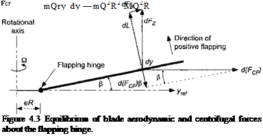
Consider now the mathematical analysis of a rotating flapping blade. Figure 4.3 shows a rigid (aeroelastically stiff) rotor blade flapping about a hinge located at a distance eR from the rotational axis. The equilibrium position of the blade is determined by the balance of aerodynamic and centrifugal forces (CF). The contributions from the gravitational forces on the blade are small relative to the other forces and can be neglected. Furthermore, because the centrifugal forces are much larger than the aerodynamic forces, the flapping (coning) angle p is usually quite small (between 3° and 6° is typical for a helicopter rotor).

Assume first for simplicity that the flapping hinge is at the rotational axis, that is, e = 0. For other than teetering rotor designs (see Section 4.13.1), the flapping hinge is always offset a small distance from the rotational axis, but this does not alter the fundamental physics of the blade dynamics problem. The rotational speed about the axis is Q radians per second and is constant. Assume a uniform mass per unit length of the blade, m. Consider a small element of the blade of length dy. The mass of this element is mdy. The forces on the element are aerodynamic and centrifugal. The contribution of this small element to the centrifugal force acting in a direction parallel to the plane of rotation is

Подпись: (4.1)cI(Fcf) = (mdy)yQ2 = mQ2y dy.

К

Equilibrium about the Flapping Hinge Подпись: (4.2)

Therefore, the total centrifugal force acting on the blade is

where the mass of the uniform blade is M (= mR). Notice that the centrifugal forces increase linearly in proportion to blade mass and length and are also proportional to S32. If the blade is coned up at some angle ft, then the contribution of this small element to the CF acting in a direction perpendicular to the blade is

d(FcF) sin ft = (mdy)yQ,2 sin ft ту іl2 ft dy. (4.3)

Подпись: CF Equilibrium about the Flapping Hinge Подпись: (4.4)

The moment about the flapping hinge (at the rotational axis) as a result of the centrifugal forces produced by all the elements is, therefore,

The aerodynamic moment about the flap hinge, Mp, depends on the distribution of lift, L, across the blade, that is,

Mp — — f Ly dy. (4.5)

Notice that the negative sign indicates that the aerodynamic moment is in the opposite direction to the centrifugal moment. The rotating blade will reach an equilibrium position where the CF moment about the hinge is equal and opposite to the aerodynamic moment about the hinge. Therefore, the equilibrium equation can be written as

Подпись: (4.6)Подпись: (4.7)Mp + Mqf — 0

and so the equilibrium or coning angle fto will be given by 3 f Lydy

о JO_____

P0 MQ2R2 ‘

This result is valid for any form of the aerodynamic loading over the blade. Also, the flapping hinge has been assumed to lie at the rotational axis of the rotor. For a parabolic distribution
of loading of lift over the blade (no blade twist), the center of lift will be located at 3/4 blade radius so that

Подпись: (4.8)3

— R x blade lift.

4

Подпись: M, Подпись: - R x blade lift. 3 Подпись: (4.9)

A rotor with ideal twist and uniform inflow will produce a linear (triangular) lift loading, which has a center of lift located at 2/3 blade radius, that is,

Therefore, it is clear that this latter case will produce a smaller aerodynamic moment about the hinge for the same total blade lift. For the case where the blade lift is distributed in a triangular manner across the blade (ideal twist) the coning angle /Зо is determined from

2 Подпись: (4.10)-2

-R x blade lift——- R Fcf P — 0

З.3й

Подпись: A) Подпись: blade lift centrifugal force
Подпись: (4.11)

or in general for given lift distribution

The important point to remember is that the coning angle increases in proportion to rotor thrust and decreases inversely with centrifugal forces. In other words, increasing either blade mass or rotor speed will decrease the coning angle.

In practice the flapping hinge is not normally at the rotational axis (except for teetering rotors) but is offset by a small distance, e R. Typically, e < 0.15. In this case, the aerodynamic moment about the flap hinge, Mp, is

Мр = – f Ly dy. (4.12)

JeR

Подпись: MQF
Equilibrium about the Flapping Hinge Подпись: (4.13)

Also, the CF moment about the hinge is

Подпись: A) Подпись: x n9 /1 i ivi ь£“л~(і -те) Подпись: (4Л4)

where M — mR( 1-е). Therefore, in this case the coning angle will be given by

Types of Rotors

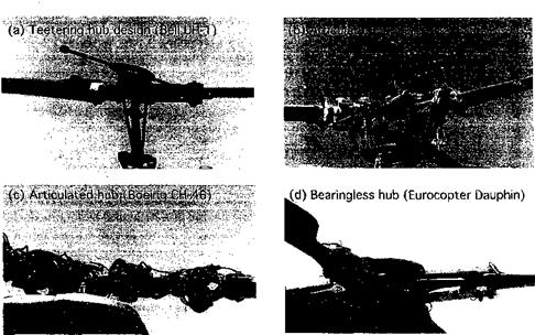
There are basically four types of helicopter rotor hubs in use. These are the teetering design, the articulated design, the hingeless design and the bearingless design. A teetering rotor has two blades that are hinged at the rotational axis (i. e., on the shaft) and uses no independent flap or lead-lag hinges. The well-known Bell (Young) design shown in Fig. 4.2(a) is an example of a teetering rotor design. The blades are connected together, so that as one blade flaps up the other flaps down like a seesaw or teeter board. A separate pitch or feathering bearing on each blade allows for cyclic and collective pitch capability. A stabilizer bar may be included, which acts like a gyroscope maintaining its orientation in space and introduces a flapping-blade cyclic pitch feedback, which gives the helicopter

Types of Rotors

Figure 4.2 Various types of rotor hubs, (a) Bell teetering hub design. Notice the bob weights attached to the stabilizer bar. (b) An articulated hub, in this case with coincident flapping and lag hinges, (c) An articulated hub, with the lag hinge outboard of both the flap and feathering bearing, (d) A bearingless hub, where the mechanical hinges are replaced by flexures.

increased flight stability. The teetering design has the advantage of being mechanically simple with a low parts count and it is easy to maintain. One disadvantage of the design is that it can have a relatively high parasitic drag in forward flight, in part because of the stabilizer bar. On later teetering rotor designs, the stabilizer bar has been removed.

A variation of the teetering design is the underslung teetering hub, an example being used on the Bell-Huey series of helicopters. Here, the blades are given a precone angle so that a downward (negative) bending component resulting from the centrifugal forces produced by blade rotation eliminates the upward (positive) bending moment at the hub resulting from the aerodynamic loads. However, any precone displacement will move the center of gravity of the rotor system above the axis of the teetering hinge, and this can introduce an undesirable coupling into the rotor system through Coriolis effects. To prevent this, the rotor is underslung below the teetering hinge to minimize the center of gravity movement relative to the shaft. A problem, however, that has arisen with underslung teetering rotor designs is mast bumping, which occurs when the rotor is lightly loaded (such as in a push-over maneuver) and excessive blade flapping causes the blade hub to contact the rotor shaft. While snubbers are used to help prevent this, repetition of the problem can result in damage to the rotor shaft. Another variation of the teetering design, called the gimbaled hub, is used on tilt-rotor aircraft such as the V-22 Osprey, where the three blades and the hub are attached to the rotor shaft by means of a gimbal or universal joint.

A large number of helicopters use conventional or fully articulated rotor hubs. Here, mechanical flap and lead-lag hinges are provided on each blade along with a feathering bearing. Different helicopters use various sequences of hinges and bearings, and this af­fects the dynamics of the rotor system. Many Sikorsky helicopters use coincident flap and lead-lag hinges, with the feathering bearing located further outboard [see Fig. 4.2(b)].

The Boeing CH-46 and CH-47 helicopters use a lead-lag hinge outboard of the feathering bearing [see Fig. 4.2(c)]. In both cases, because of the relatively low drag and aerodynamic damping in the lead-lag plane, mechanical dampers are fitted at the lag hinges. Needless to say, the articulated rotor design is mechanically complicated with many component parts and is relatively expensive to maintain. It is also heavy and produces relatively high drag in forward flight. Nevertheless, the fully articulated design is the classic approach to providing blade articulation on a helicopter and in practice it has proven mechanically reliable but with relatively high maintenance costs because of the large number of parts.

A hingeless rotor design eliminates the flap and lead-lag hinges by using a flexure to accommodate blade motion. A feathering bearing is still used to allow for pitch changes on each blade. The advantage of a hingeless design is that it is mechanically simple. However, because blade articulation is achieved by the elastic flexing of a structural beam, the design of such rotors is rather complicated. In addition, because it is not possible to completely isolate the flapping motion from the lead-lag motion there is usually significant flap-lag coupling to contend with. Major advantages of the hingeless hub design include mechanical simplicity with a low parts count and low aerodynamic drag. In addition, the relatively stiff hub design gives the helicopter a powerful response to control inputs and increased maneuvering capability.

Bearingless hub designs are a relatively new innovation. In addition to eliminating the mechanical flap and lead-lag hinges, the bearingless hub also eliminates the feathering bearing. All three degrees of motion are obtained by bending, flexing, and twisting of the hub structure. Needless to say, obtaining the required stiffnesses is only possible by means of new fatigue-resistant composite materials such as glass, carbon, and Kevlar, which can be arranged so that load paths, stiffnesses, and couplings can all be controlled. Designing a bearingless hub is difficult and requires a detailed (i. e., finite-element based) structural dynamic analysis. While retaining all the advantages of a hingeless design, bearingless hubs can be particularly susceptible to aeromechanical instabilities as a result of low in-plane damping of the lead-lag blade motion.

Rotating Blade Motion

It is sufficient to say that it [the dissymmetry of lift on the rotor] is completely eliminated by the articulation of the rotor blades, which no longer set up a powerful inherent force which must be overcome in order to control the craft.

Juan de la Cierva (1931)

4.1 Introduction

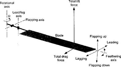
The interdependent coupling of the aerodynamic forces produced on the rotor blades and the resulting blade motion is the key to understanding the behavior of the blade response and in developing a means of giving the pilot positive control over the rotor system. A distinctive feature of helicopter rotors is that articulation in the form of flapping and lead-lag hinges is incorporated at the root of each blade. These may be mechanical hinges, or modem rotor hub designs may use semi-rigid or hingeless flexures that allow motion about a “virtual” hinge location. In either case, the hinges allow each blade to independently flap and lead or lag with respect to the hub plane under the action of varying aerodynamic lift and drag loads (Fig. 4.1). The idea of a flapping hinge for a rotor was first patented by Bartha & Madzer (1913). However, the flapping hinge was first successfully used on an aircraft by Juan de la Cierva with his autogiros (see Chapter 12). The addition of a lead-lag hinge allows in-plane motion of the blade in response to the Coriolis accelerations and forces that are produced when the radius of gyration of the blade changes by virtue of flapping. A pitch bearing is also incorporated into the blade design to allow the blades to feather, providing an ability to change their pitch. This can be done collectively (together) on all blades, thereby changing the magnitude of the rotor thrust, or cyclically, that is, with respect to blade azimuth, thereby changing the phasing of the aerodynamic loads over the disk. The latter allows the rotor disk to tilt so as to reorient the rotor thrust vector and provide the pilot with pitch and roll control of the helicopter.

In hovering flight, the flow field is azimuthally axisymmetric and so each blade en­counters exactly the same aerodynamic environment. The blades flap up and lag back with respect to the hub and reach a steady equilibrium position under the action of these steady (nonazimuthally varying) aerodynamic and centrifugal forces. The blades will “cone” up to form a static balance between the blade aerodynamic forces and the centrifugal forces, and the rotor disk plane takes on some orientation in inertial space. The centrifugal forces are dominant and sc the coning angles on helicopter rotors always remain relatively small (a few degrees). In addition, the aerodynamic drag forces on the blades cause them to lag back. Because the drag forces are only a fraction of the lift forces and are overpowered by the centrifugal forces, the lag angle displacements are even smaller than the coning angles.

As the helicopter moves into forward flight, the asymmetry of the onset flow and dynamic pressure over the disk produces aerodynamic forces that are functions of blade azimuth position (i. e., cyclically varying airloads are now produced). The flapping hinge allows each blade to freely flap up and down in a periodic manner with respect to azimuth angle

Rotating Blade Motion

Figure 4.1 Schematic showing flapping, lead-lag and feathering motion of a rotor blade.

under the action of these varying aerodynamic loads. The blades reach an equilibrium condition again when the local changes in angle of attack (AoA) and the aerodynamic loads produced as a result of blade flapping are sufficient to compensate for the local changes in the airloads resulting from variations in dynamic pressure. In the words of Cierva, the blades were “free to move in a sort of flapping motion wherever they liked according to the effects of the air upon them.” The rotor disk, therefore, naturally wants to takes up a new orientation in space, although this may not be the desired orientation. Positive control of the blade pitch is required to cyclically adjust the magnitude and phasing of the aerodynamic loads to bring the rotor to a desired orientation.

Some of the first theoretical studies of blade flapping and rotor response were undertaken in Great Britain by Lock (1927), Glauert (1928), and Squire (1936), motivated initially by the success of the autogiro. In the United States, Wheatly (1934), Sissingh (1939, 1941), Bailey (1941), and Wald (1943) were responsible for most of the initial work in under­standing rotor blade flapping behavior in forward flight. Nikolsky (1944, 1951) gave one of the first formal treatments of the various problems in rotor dynamics and the effect on rotor performance. Bramwell (1976) and Johnson (1980) give the most thorough textbook expositions of rotating blade dynamics and rotor response. Loewy (1969), Reichert (1973), Friedmann (1977, 2004), and Chopra (1990) give good reviews of the complicated coupled dynamics and the various aeroelastic problems associated with helicopter rotors from a research perspective.

Chapter Review

Подпись: /Тї ГГ'-ГЧ : Л. 1 , ]_і lie uiauc сіоніст uicuiy dsz і; is a puwcnui шиї iur me aeruuynaiiiic analysis ui helicopter rotors. It forms the basis for nearly all modern computational methods used for rotor performance, airloads, and aeroelastic analyses. The basic ideas consist of representing the airloads on 2-D sections of the blades, and integrating their effect to find the performance of the rotor as a whole. This allows tremendous flexibility in the rotor analysis and also allows the effects of airfoil shape to be examined, along with the effects of the Reynolds number and the Mach number, and even some elementary effects associated with nonlinear aerodynamics and stall.

On the basis of certain assumptions, it has been shown how the combined blade element momentum theory (BEMT) can provide analytic results about how to design the rotor in terms of optimum blade planform and blade twist distribution to enable maximum hovering efficiency. Whereas the simple momentum theory shows that the rotor should be designed for low disk loading, the blade element approach allows the trade-offs associated with the interrelated effects of disk loading, blade tip speed, blade loading, blade twist, and blade planform to be examined. While the BEMT theory is by no means complete, it paves the way

ЛІ nfll/ll AO /IАП1 rt"T f/N n/4*V»A ЛПАЛ1І1А/1 ПЛ+ Л T+ « n А їм 11 ft T

iui initial in iuiui u&digii ш nit^t duiu& sti ui l^uii^iii^iud. it id uit; anility

to help design the rotor from the onset that gives these methods great practical utility, and they can also be used as check cases for other and more advanced types of methods.

In forward flight, the BET allows for the calculation of the nonaxisymmetric airloads over the rotor disk. Besides the need to account for the effects of blade flapping motion (which are considered next in Chapter 4), this chapter has also introduced the ideas that more accurately representing the effects of the rotor wake is one key to the successful use of the BET. The use of other than uniform inflow models provides a better representation of the effects of the rotor wake and a better overall physical picture of the rotor aerodynamics problem. While inflow models are not completely rigorous, especially at low forward flight speeds, they give
reasonable descriptions of the induced velocity field over the rotor disk and may be well suited for the analysis of many rotor problems. Their computational simplicity allows for easy integration into blade element based rotor models and may allow for the inclusion of unsteady aerodynamic effects as well (see Chapter 8). However, it must be remembered that in many situations where the individual tip vortices come close to the disk (especially in low speed forward flight, during maneuvers, or in descents) the induced velocity distribution is considerably more complicated than can be prescribed by these simple inflow models. The use of prescribed – or free-vortex methods provides the fidelity necessary under these conditions, albeit at much greater computational expense (see Chapter 10).

However, before the rotor problem in forward flight can be fully enunciated, it is neces­sary to consider properly the effects of the rotor blade motion on the aerodynamic forces. Because the aerodynamics and blade motion are intrinsically coupled, they must be solved simultaneously as a system. This then allows the calculation of rotor trim, that is, the control inputs required to orient the rotor in a direction to meet vehicle lift, propulsion, and control requirements. These issues are considered in the following chapters.