Category Principles of Helicopter Aerodynamics Second Edition

Blade Element Momentum Theory (BEMT)

The blade element momentum theory (BEMT) for hovering rotors is a hybrid method that was first proposed for helicopter use by Gustafson & Gessow (1946) and Gessow (1948) and combines the basic principles from both the blade element and momentum theory approaches. The principles involve the invocation of the equivalence between the circulation and momentum theories of lift. With certain assumptions, the BEMT allows the inflow distribution along the blade to be estimated.

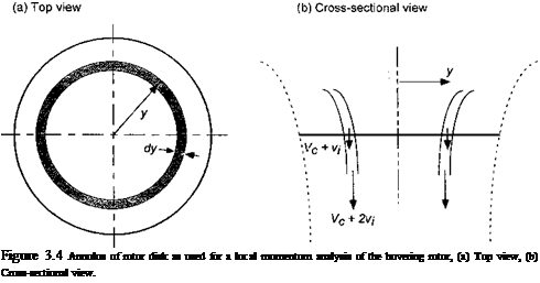
Consider first the application of the conservation laws to an annulus of the rotor disk, as shown in Fig. 3.4- This is the essence of Froude’s original differential theory for pro-

прііргс in qyi q1 mritinn TVne annulne і c at о Hicfon^A лі fmm іЬа rAfotinnal ovic onrl

J 111 U/V1U1 11IV/1,1 vy 11. 1 lUO UUUU1UO Ш Ul U U1JIUUV/V у 11 V/J 11 IUV 1 J LUUWl IU1 ci/yio, шш

has a width dy. The area of this annulus is, therefore, dA = 2ny dy. The incremental thrust, dT, on this annulus may be calculated on the basis of simple momentum the­ory and with the 2-D assumption that successive rotor annuli have no mutual effects on each other. As might be expected, this approach has good validity except near the blade tips. The removal of this 2-D restriction requires a considerably more advanced treatment of the problem using a vortex wake theory. However, a good approximation to the tip-loss effect on the inflow distribution can be made using Prandtl’s “circulation – loss” function, which will be discussed in Section 3.3.10. Tokaty (1971) gives a good historical overview of the origins of the blade element and blade element momentum theories.

On the basis of simple one-dimensional momentum theory developed in Chapter 2, we may compute the incremental thrust on the rotor annulus as the product of the mass flow rate through the annulus and twice the induced velocity at that section. In this case the mass flow rate over the annulus of the disk is

Подпись: (3.42)Подпись:dm = pdA(Vc + Vi) = 2np(Vc + Vi)y dy, so that the incremental thrust on the annulus is

Подпись: Figure 3.4 Annulus of rotor disk as used for a local momentum analysis of the hovering rotor, (a) Top view, (b) Cross-sectional view.

dT = 2p (Vc + vi) vtdA = Anp (Vc + v{) v{y dy.

This has also been known as the Froude-Finsterwalder equation. It is more convenient to work in nondimensional quantities so that

_ dT_________ _ 2p{Vc + Vi)vjdA

T ~ pin R2)(QR)2 ~ pjrRHQR)2

– 2p(Vc + ьіЇьі(27ТУ dy) _ + Vi) / Vi / y Y y

pnR2(QR)2 ~ QR Qr)r) r)

or simply

dCT = 4АА/Г dr, (3.44)

Therefore, the incremental thrust coefficient on the annulus can be written as

dCj = 4AA, r dr = 4A (A — Ac)r dr (3.45)

because А і — A — Ac. The induced power consumed by the annulus is

dCpi = A dCj = 4A2A, r dr = 4A2 (A — Ac)r dr. (3.46)

This assumes no swirl in the wake, which is justified in Section 3.3.6. Consider first the hovering state where Ac = 0. The incremental thrust and power contributions of the annulus are given by

Подпись:

Blade Element Momentum Theory (BEMT) Blade Element Momentum Theory (BEMT)

dCp = 4A2r dr and dCpt = 4A3r dr,

Tip-Loss Factor

The ideas of a so-called tip-loss factor have been introduced in Chapter 2 and can be used to account for the effects on the rotor thrust and induced power because of the locally high induced velocities produced at the blade tips by the trailed tip vortices. The basic form of the BET permits a finite lift to be produced at the blade tip, which, of course, is physically unrealistic. The Prandtl tip-loss factor В is used to represent this loss of blade lift and can be considered as an “effective” blade radius, Re = BR. In practice, В is found to take a value between 0.95 and,0.98 for most helicopter rotors.

When the tip loss is included in the calculation of rotor thrust using the BET, one approach is to consider the outer portion of the blade, R — Re, to be incapable of carrying lift. This is the approach suggested by Gessow (1948) and Gessow & Myers (1952) and followed by Payne (1959), Johnson (1980), and others. In this case the result for the lift is given by integrating the segment lift over the effective blade span as

fB <7 9 aCi, „

CT = / – Ctr2 dr = / —- (Or" – Xr) dr. (3.33)

Jo 4 Jo 2

Подпись: CT - -аСі ZT 2 " Подпись: вр В З Подпись: Л 2 Подпись: (3.34)

For untwisted blades (в — во) and uniform inflow assumptions (A. = ■s/Cj/2), this becomes

Подпись: CT Подпись: ($tip ~ A.)— 1 Jo
Tip-Loss Factor

which can be compared to the result given previously in Eq. 3.22 with no tip losses (or Eq. 3.34 with В = 1). For a rotor with a twist distribution of the form в — (9tiP/r (as will be shown, this is known as “ideal” twist), then

Подпись: (3.35)oCia

4

In either of Eq. 3.34 or Eq. 3.35 because В is between 0.95 and 0.98, we find a 6-10% reduction in rotor thrust resulting from tip-loss effects for a given blade-pitch setting under the stated assumptions.

C*A – • __________ 1 _!_______ лЛ________ i.!„ 1___________________ J _ J________________________ J г______________ i. L _ n_______________ li.1 i-1____________________ J:_____________________ ^ J

Подпись: vh = Подпись: T 2 pAe Подпись: T 1 2p(AB2) ~ ~B Подпись: T 2~pA' Подпись: (3.36)

dUlcuy spCctRing, liic np-ioss cquanun ueauccu ниш uic riauuu нісшу аь iusl uisuusscu in Chapter 2 should be applied to the calculation of an increased inflow (for the same total thrust). Therefore, to assume that the outboard part of the blade, R — Re, is ineffective in carrying lift is not the correct interpretation of Prantdl’s theory. This fact has also been pointed out by Bramwell (1976). The correct interpretation is to consider that for the same thrust the induced inflow will be increased to a value

Подпись: 0o 3 Подпись: A. IB Подпись: (3.37)
Tip-Loss Factor

that is, Vh (or A./,) is increased by a factor В 1 compared to the case with no assumed tip losses. For untwisted blades and uniform inflow with tip losses alone, the thrust becomes

which can be compared to Eq. 3.34 with the alternative interpretation of tip loss. Eor ideal twist and uniform inflow, the thrust now becomes

Подпись: CT =Подпись:Tip-Loss Factor(3.38)

compared to the result in Eq. 3.35, which will overpredict the effects of tip loss.

Because of tip-loss effects, a real rotor will always have a higher overall average induced velocity compared to that given by momentum theory and so the induced power will also be increased relative to the simple. momentum result. Tip loss constitutes an additional source

of nonuniform inflow, and would normally be factored into the value of к. Using the BET, the induced power can be written as

Подпись: (3.39)Подпись: C‘=! гЛ і

kdCr = I – aXCy2 dr,
Jo 2

Подпись: Cp = —oCi KX 2 “ Подпись: во У Подпись: л IB Подпись: T "тес, Подпись: (3.40)

where A. must be calculated for each element. Using untwisted rectangular blades and uniform inflow assumptions, then with a tip loss the total power can be approximated by

where the induced power factor к includes the effects of both tip loss and nonuniform inflow over the remainder of the blade. As suggested in Chapter 2 by the simple momentum analysis, к approximately equals 1.25 for the rotor used in this case. In general, we can write that

Подпись: (3.41)1

к = — +kx + k0,

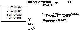
where Kx accounts for the effects of nonuniform inflow and k0 accounts for other miscel­laneous induced losses. Figure 3.3 shows the variation in power required versus collective pitch for four rotors with increasing solidity. Again, the data are taken from Knight and Hefner (1937). The calculations have used a tip-loss factor, В — 0.97, к = 1.25, and CdQ = 0.011. The result in Eq. 3.40, with the stated assumptions, correlates well with the measured data but now shows a slight underprediction at the higher collective pitch angles. For the most part, this is because of the higher drag coefficients associated with boundary layer thickening and the onset of blade stall, the effects of which tend to increase the profile power above that obtained by assuming a constant profile drag coefficient.

Torque-Power Approximations

According to the BET, the incremental power coefficient on the rotor can be written as

dCP = dCQ = І (фСі + Cd) r3 dr. (3.27)

Using the result that X — фг and expanding out Eq. 3.27 gives

dCp — —фСіг3 dr + — C^r3 dr

= —Cikr" dr H—Cdr3 dr 2 2

= dCP. +dCPo, (3.28)

Torque-Power Approximations Подпись: (3.29)

where dCpj is the induced power and dCPo is the profile power. Recall from Eq. 3.15 that the incremental thrust coefficient can be written as dCp — oCir2dr so that dCpt — XdCp. Therefore,

and the total power coefficient is

Подпись: (3.30)pr= /*1 і

CP = I XdCp + I – crCdr3dr. Jr=о Jо 2

By assuming uniform inflow and Cd = Cdo = constant, then after integration we obtain

Подпись: (3.31)Cp = XCp + – ffQ0.

О

But in hover with uniform inflow then we know that X = VCY/2, and so

C3/2 1

Cp = -2=- + – aCdo. (3.32)

Under these assumptions it is apparent that the first term in this latter equation reduces to the simple momentum theory result given previously in Chapter 2, as it should. The second term is the extra power predicted by the BET that is required to overcome profile drag of the rotor blades, which was a concept first introduced in Eq. 2.42.

Linearly Twisted Blades, Uniform Inflow

Linearly Twisted Blades, Uniform Inflow Подпись: (3.25)

All helicopter rotor blades use some amount of spanwise twist in their shape, although in different forms and with different amounts. As will be shown, the use of blade twist provides the rotor with several important performance advantages. Many helicopter rotor blades are designed with a linear twist, so that 0 takes the form 6(r) — 6q + r0tw, where t9tw is the blade twist rate per radius of the rotor (i. e., in degrees per rotor radius or the equivalent in degrees per unit length of blade). Using this variation in 0(r), we get

Comparing this latter equation with Eq. 3.22 shows an interesting result, namely that a blade with linear twist has the same thrust coefficient as one of constant pitch when в is set to the pitch the twisted blade defined at the 3/4-radius [see also Gessow & Myers (1952) and Johnson (1980)].

Thrust Approximations

Based on steady linearized aerodynamics, the local blade lift coefficient can be written as

Ci = Cta(a – a0) = С[а(в – «о – Ф), (3.19)

where Cia is the 2-D lift-curve-slope of the airfoil section(s) comprising the rotor, and «о is the corresponding zero-lift angle. For an incompressible flow, C/e would have a value close to the thin-airfoil result of 2n per radian. Although C/a will take a different value at each blade station because it is a function of local incident Mach number and Reynolds number, an average value for the rotor can be assumed without serious loss of accuracy (i. e., C/a = constant). Also, unless otherwise stated, it will be assumed that «о can be combined into в.

Therefore, C[a can be taken outside of the integral sign giving

Подпись:Подпись: (3.21)cT = f Cir2 dr = aCi« f (0 – ФУ2 dr>

^ Jo 2 Jq

and using the result that ф = к/r, then the thrust coefficient can be written as

1 f1

Ст — – crC/a I (Or2 — kr) dr.

2 ■ . Jo

Untwisted Blades, Uniform Inflow

Thrust Approximations Подпись: 'B0r3 3 Thrust Approximations Подпись: (3.22)

For a blade with zero twist, В = constant = во. Also, for uniform inflow velocity, which is assumed in simple momentum theory, к = constant. Therefore, in this case the thrust coefficient is given by

To find the direct relationship between Ct and the blade pitch, we can use the relationship between Ct and к as is given by the simple momentum theory in Chapter 2 (i. e., A.,- = kh =

/7S 7nT mi _ .. _ jy _

Подпись: CT = -o"C/c Подпись: во _ і fc£ 3 2V 2 Подпись: (3.23)

f^T/ z )• A nereiore,

Thrust Approximations Подпись: CT Подпись: (3.24)

This equation must be solved iteratively to find Ct for a given value of Bo. Alternatively, solving directly for the pitch angle, Bq, in terms of an assumed thrust gives

The first term is the blade pitch required to produce thrust, and the second term is the additional pitch required to compensate for the inflow resulting from that thrust.

Figure 3.2 shows results for the thrust versus collective pitch for four rotors of different

сліігіїіл; г ГКо <avnarimflnto1 rlo+o оі*д tolzon fm-m fliA avnorlmonfc ni rrVif jfr Uafnor (1

OV/llUllj. JLUV VA^rVlUUWlUm UttlU CUV UUVV11 UVU1 111V VApVlllllVUtJ VI ivmgui LV X1VJLJL1VA r

who tested subscale rotors with no blade twist. These rotors involved increasing the number of blades to arrive at larger solidity, but there are no experiments that have examined solidity effects independently of blade number. The effect of number of blades (other than solidity) on the rotor aerodynamics, however, is small. For the purposes of these calculations, C/ff was set to a value of 5.73/radian, which represents a small reduction of the 2-D thin-airfoil result of 27r/radian because of finite airfoil thickness and Reynolds number effects. The agreement between Eq. 3.23 and the measurements is found to be good, although there is a slight overprediction of the thrust because so far the nonuniformity of the inflow and nonideal effects, such as tip loss, have not been accounted for in the theory.

5 10

Подпись:

Подпись: 0.015 Thrust Approximations
Подпись: О c Ф 'o it CD О О to гз
Thrust Approximations

Blade-pitch angle, 0О – deg.

Figure 3.2 Variation in rotor thrust coefficient with collective pitch for rotors with different solidities. Data source: Knight & Hefner (1937).

Blade Element Analysis in Hover and Axial Flight

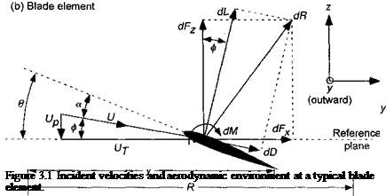
The blade element approach for the analysis of helicopter rotors has been well established in the prior literature – see Payne (1959), Bramwell (1976), Johnson (1980), and Prouty (1986). The resultant local flow velocity at any blade element at a radial distance у from the rotational axis has an out-of-plane component Up — Vc + normal to the rotor as a result of climb and induced inflow and an in-plane component Up = Ely parallel to the rotor because of blade rotation, relative to the disk plane. The resultant velocity at the blade element is, therefore,

U = yju2 + U2P. (3.1)

The relative inflow angle (or induced angle of attack) at the blade element will be (Vr Up „ …

ф = tan * і — і ^ — tor small angles. (J. z)

Up / ‘ Up

Thus, if the pitch angle at the blade element is в, then the aerodynamic or effective AoA is

Up

a = в — ф = в—– -. (3.3)

Up

The resultant incremental lift dL and drag dD per unit span on this blade element are

1 9 1 9

dL = – pU2cCi dy and dD = ~pU2cCd dy, (3.4)

where Ci and Cd are the lift and drag coefficients, respectively. The lift dL and drag dD act perpendicular and parallel to the resultant flow velocity, respectively. Notice that the quantity c is the local blade chord. Using Fig. 3.1 these forces can be resolved perpendicular and parallel to the rotor disk plane giving

dFz = dLcosф — dDsinф and dFx = dL sin0 + dD cos0. (3.5)

Therefore, the contributions to the thrust, torque, and power of the rotor are

dT = NbdFz, dQ = NbdFxy and dP = NbdFxQy, (3.6)

where Nb is the number of blades comprising the rotor. Notice that in the hover or axial flight condition, the aerodynamic environment is (ideally) axisymmetric and the airloads
are independent of the blade azimuth angle. Substituting the results for d Fx and d Fz from Eq. 3.5 gives

dT = Nb(dL cos0 — dD sin0),

(3.7)

dQ – Nb(dL sinф + dD cosф)у,

(3.8)

dP — Nb(dL sinф + dDcosф)Qy.

(3.9)

For helicopter rotors the following simplifying assumptions can be made:

1. The out-of-plane velocity Up is much smaller than the in-plane velocity Uj, so that U = yjUj + Up ~ Ut – This is a valid approximation except near the blade root, but the aerodynamic forces are small here anyway.

2. The induced angle ф is small, so that ф = Up/Ut – Also, sin ф — ф and cos ф = 1.

3. The drag is at least one order of magnitude less than the lift, so that the contribution dDsїnф (or dDф) is negligible.

Applying these simplifications to the preceding equations results in

dT = NbdL,

(3.10)

dQ = NbUf)dL + dD)y,

(З. И)

dP = NbQ(4>dL +dD)y.

(3.12)

Blade Element Analysis in Hover and Axial Flight

Proceeding further, it is convenient to introduce nondimensional quantities by dividing lengths by R and velocities by QR. Hence, r = у/R, and Uj QR = Qy/QR — y/R = r. Also, dCT = dT/pA(QR)2, dCQ = dQ/pA(QR)2R, and dCP = dP/pA(QR)3. The inflow ratio can be written as

This is one of the most fundamental equations for rotating-wing analysis by means of the BET. By a similar approach, it can be shown that the rotor-torque coefficient increment is

Подпись:Подпись: dCQ=dCpdQ Nb(si>dL + dD)y 1

~ pA{SlR)2R ~ p(TtR2)(QR)2R ~ 2

= (ФСі + Cd)r3 dr, which will be noted to represent the sum of an induced part and a profile part.

3.2.1 Integrated Rotor Thrust and Power

To find the total Cj and Cq, the incremental thrust and power quantities derived above must be integrated along the blade from the root to the tip. For a rectangular blade, the thrust coefficient is

Подпись: Qr2 dr,Blade Element Analysis in Hover and Axial Flight(3.17)

Blade Element Analysis in Hover and Axial Flight Подпись: (3.18)

where the limits of integration are r — 0 at the root to г = 1 at the tip. For the corresponding torque or power coefficient

using the general result that ф = Xfr from Ea. 3.13.

To evaluate Cj and Cp it is necessary to predict the spanwise variation in the inflow, X, as well as the sectional aerodynamic force coefficients, С/ and Cd. If 2-D aerodynamics are assumed, then С/ = C/(a, Re, M) and Cd — Cd(a, Re, M), where Re and M are the local Reynolds number and Mach number, respectively (see Chapter 7). Also, a = a(Vc, 0, Vi) and u, — u,(r). Because these effects cannot, in general, be expressed as simple analytic results, it is necessary to numerically solve the integrals for Cp and Cp. However, with certain assumptions and approximations, it is possible to find closed-form analytical solutions. These solutions are very useful because they serve to illustrate the fundamental form of the results in terms of the operational and geometric parameters of the rotor. They also provide exact check cases for the numerical solutions to the blade element theory.

Blade Element Analysis

Whatever progress the airplane might make, the helicopter will come to be taken up by advanced students of aeronautics.

Thomas Edison (circa, 1920)

3,1 Introduction

The blade element theory (BET) forms the basis of most modem analyses of helicopter rotor aerodynamics because it provides estimates of the radial and azimuthal distributions of blade aerodynamic loading over the rotor disk. The BET assumes that each blade section acts as a quasi-2-D airfoil to produce aerodynamic forces (and moments). Tip loss and other empirical factors may be applied to account for three-dimensional effects. Rotor performance can be obtained by integrating the sectional airloads at each blade ele­ment over the length of the blade and averaging the result over a rotor revolution. Therefore, unlike the simple momentum theory, the BET can be used as a basis to help design the rotor blades in terms of the blade twist, the planform distribution and perhaps also the airfoil shape to provide a specified overall rotor performance.

The idea of the BET was apparently first suggested by Drzewiecki (1892, 1920) for the analysis of airplane propellers, although Glauert (1935) indicates that in the nineteenth century F. W. Lanchester also made contributions to solving the problem – see Lanchester (1915). At the beginning of the twentieth century, there was considerable scientific debate about the proper theoretical aerodynamic analysis of propellers and helicopter rotors, mainly between Stefan Drzewiecki and Louis Breguet – see Liberatore (1998). The principles of blade element theory assume no mutual influence of adjacent blade elements sections; these sections are idealized as 2-D airfoils. However, the effects of a nonuniform “induced inflow” across the blade (its source from the rotor wake) is accounted for through a modification to the angle of attack (AoA) at each blade element. Unless we make some simple analytic assumption for the distribution of induced velocity over the disk, such as a uniform or linear distribution, the blade element calculation is quite a formidable undertaking because it must more precisely represent the highly nonuniform velocity field induced by the vortical wake trailed from each blade, as well as to account for the influence of all the blades and possibly airframe components. However, if the induced velocity can be calculated, or even approximated, then the net thrust and power and other forces and moments acting on the rotor can be readily obtained.

In an extension to the basic approach, the BET and momentum theories were linked together by Reissner (1910,1937, 1940), de Bothezat (1919), and Glauert (1935) to define the induced velocity or induced AoA distribution. A similar approach for hovering helicopter rotors was developed by Gustafson & Gessow (1946) and Gessow (1948), and the approach is reviewed in Gessow & Myers (1952). The BET was extended to explicitly include the influence of the vortical wake (and the other blades) through an induced AoA component

Blade Element Analysis

as calculated by means of the Biot-Savart law. These basic ideas were first pursued at the beginning of the twentieth century by Joukowski – see Tokaty (1971), Glauert (1922), Bienen & von Karman (1924), and Lock et al. (1925). Betz (1919, and appendix therein by Prandtl) and Goldstein (1929) developed a prescribed vortex wake theory for lifting propellers. This work was later extended by Theodorsen (1948). The early work with the technique as it applies to propellers is reviewed by Glauert (1935). Knight & Hefner (1937) were among the first to apply blade element and prescribed vortex wake principles to the calculation of the helicopter rotor problem. Coleman et al. (1945), Castles & De Leeuw (1954), and Castles & Durham (1956) later extended this work to helicopters operating in forward flight.

Blade Element Analysis

Figure 3.1 shows a sketch of the flow environment and aerodynamic forces at repre­sentative blade element on the rotor. The aerodynamic forces are assumed to arise solely from the velocity and AoA normal to the leading edge of the blade section. The effect of the radial component of velocity, Ur, on the lift is usually ignored in accordance with the independence principle; see Jones & Cohen (1957). However, the Ur component will affect the drag on the blade in forward flight and should be included in this case. The measured 2-D aerodynamic characteristics of the airfoil as a function of AoA can be assumed for

the purposes of calculating the. resultant lift and pitching moment on each blade element. Such results are available in the published literature for a large number of airfoils and over a wide range of operating conditions (see Chapter 7). The inflow angle of attack, ф, arises, primarily because of the velocity induced by the rotor and its wake. Therefore, the induced velocity serves to modify the direction of the relative flow velocity vector and so alters the AoA at each blade element from its 2-D value. This inflow velocity also inclines the local lift vectors, which by definition act perpendicular to the resultant velocity vector at the blade element and, therefore, provides a source of induced drag (drag resulting from lift) and is the source of induced power required at the rotor shaft.

Chapter Review

The theories and results described in this chapter have shown that using certain assumptions and approximations, the application of the conservation laws of aerodynamics in an integral form has permitted an understanding of the factors that influence the basic performance of the helicopter rotor. The so-called momentum theory has allowed a quantifi­cation of the thrust and power of a lifting rotor, and it has been shown how these quantities are related to the downwash (inflow) velocity through the rotor. The momentum method has permitted a preliminary evaluation of rotor performance in hover, climb, and descent. It has been shown that the disk loading is a kev Darameter governing rotor Derformance. and

‘ " ‘ —– C? “ ~ " — J I……….. G – " C2 Ї. ‘ —

the need for a low disk loading is essential to give a helicopter good hovering efficiency. The ideas of power loading and figure of merit have been introduced as quantities that can help in designing the rotor as well as to compare the relative efficiency and performance of two different rotor designs.

To account for various nonideal effects that have their origin in the viscosity of the air, it has been shown how the basic momentum theory can be modified empirically to give a methodology that is in substantially better quantitative agreement with experimental mea­surements of rotor performance, while still retaining the simplicity of the overall method. The basic momentum theory has also been extended to forward flight, for which numerical solutions are generally required to solve for the inflow through the rotor disk. These nu­merical techniques have been examined, along with the identification of limitations in their use. Finally, the ideas embodied in momentum theory have been extended to coaxial and partly overlapping rotors such as tandems. It has been shown why there are rotor-on-rotor interference effects associated with these designs, which can reduce the net aerodynamic performance of the rotor system.

Despite the advantages of momentum theory in providing clarity of insight into the basic aspects of the helicopter rotor problem, it has many limitations. For example, it provides no information about the distribution of loads over the blade or as to how the rotor blades should be designed (i. e., the planform, twist, thickness distribution, airfoil sections.) to produce a given performance. Furthermore, the effects of blade motion (i. e., flapping) on the rotor behavior have not yet been considered. However, these are limitations that can be overcome by using more advanced methods based on a blade element analysis of the rotor blades, which is considered in the next and subsequent chapters.

Tandem Rotor Systems

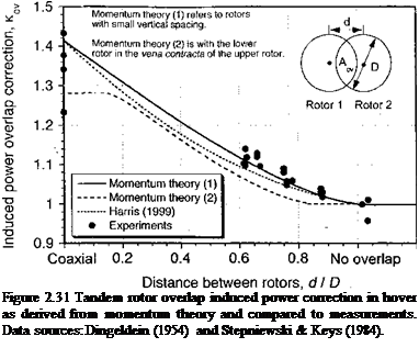
The basic momentum analysis can also be extended to overlapping tandem rotors. Tandem rotor designs are sometimes used for heavy-lift helicopters because like the coaxial design all of the rotor power can be used to provide useful lift. However, like a coaxial design, the induced power of partly overlapping tandem rotors is found to be higher than that of the two isolated rotors (Fig. 2.31). This is because one of the rotors must operate in the slipstream of the other rotor, resulting in a higher induced power for the same thrust. The tandem rotor problem is discussed extensively by Stepniewski (1955) and Stepniewski & Keys (1984). Other results for twin rotor performance are given by Fail & Squire (1947) and Sweet (1960).

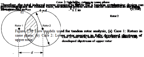
The analysis of overlapping rotors from the perspective of momentum theory is normally based on the ideas of overlapping areas – see Payne (1959). Let Aov = mA be the overlap area according to the inset shown in Fig. 2.31 and also Fig. 2.32. The rotors are assumed to have no vertical spacing, which is Case 1 shown in Fig. 2.32. By means of the geometry of the problem it can be shown that

Подпись: (2.164)

Подпись: Figure 2.31 Tandem rotor overlap induced power correction in hover as derived from momentum theory and compared to measurements. Data sources: Dingeldein (1954) and Stepniewski & Keys (1984).

m’ = = — Г# — — sinfll, where в = cos 1 (—^ .

А ті D dJ

Tandem Rotor Systems

Let T and T2 be the thrusts on the two rotors, which may be unequal. Therefore, m(T + T2) is the thrust on the overlapped region. Based on uniform inflow assumptions then the induced power of the rotors consumed by each of the areas is

(1 – m’yrV1 + (1 – m’)7f2 + m'(T + T2f/2

Tandem Rotor Systems

where A is the disk area of any one of the two rotors and T is the total system thrust as generated by both rotors. If it is assumed that each rotor carries an equal fraction of the total thrust (T[ — Tf) then

= kov = 1 + (V2 – l)m’ = 1 + 0.4142 m’, (2.169)

Подпись: ^ov Подпись: (2.170)
Tandem Rotor Systems Tandem Rotor Systems Tandem Rotor Systems

where m! is given by Eq. 2.164. Harris (1999) suggests an approximation to кт, where

The assumptions made in the derivation of the previous equations are not critical, as it can be shown that if each rotor carries a different fraction of the total thrust then /cov is only slightly higher than if an equal fraction is assumed (see Question 2.21). Notice that in Eq. 2.169 asm’ -> 1, which is a coaxial, then kow •v/2, as before. When the rotors are completely separated with no overlap (m’ = 0), then kow —> 1, as is required for isolated
rotor performance. The result of Eq. 2.169 is plotted in Fig. 2.31 in terms of the spacing ratio d/D, where d is the spacing between the two rotor axes and D is the rotor diameter. As d becomes larger and the rotors are more separated, the induced power overlap correction factor approaches unity.

An alternative analysis is to consider a situation where the lower rotor of the tandem operates in the fully contracted slipstream of the upper rotor – see Case 2 of Fig. 2.32. Here the overlap area is affected by the contracting wake from the upper rotor and m’ must be determined by numerical integration. When the rotors are in the same plane then m’ is given by Eq. 2.164. The analysis proceeds using as similar flow model to that shown previously in Fig. 2.27. Using the conservation of momentum, the thrust on the upper and lower rotors are

Подпись: (2.171) (2.172) (2.173) Tu = (p Avu)(2vu)

and

Ti = (mw)i – (mw)u.

The mass flow rates through the two rotors are

mu = m p A(2vu) and mi = (1 — m’)p Avi + m p A(i>/ + 2vu).

Assuming the thrust on the upper and lower rotor are equal gives

[(1 – m’)p Avi + m’p A(vi + 2vu)]wi – [m’p A(2uM)](2u„) = (p Avu)(2vu),

(2.174)

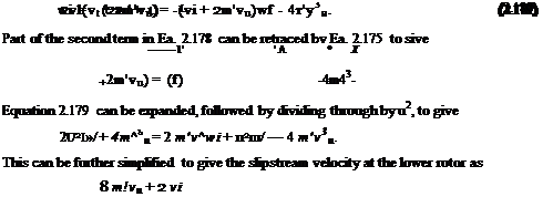
which after simplification becomes

Подпись: — (Vi + 2 mvu).Подпись:vl(4m’ + 2)

Щ

From the conservation of energy

Pi = T[(l – m’)vi + mvi + 2vu)] = Qmw2^ – Qraw2^ , (2.176)

which can be simplified to get

Подпись: (2.177)

Tandem Rotor Systems

T(vi + 2m vu) = A(vi + 2m’vu)wf – 4p m’Av3u. Equation 2.171

The dependency of кт on rotor overlap has been measured experimentally using subscale rotor models. The amount of these data is relatively scarce compared to single rotor data, but the available results have been collated by Stepniewski & Keys (1984) from several sources including Sweet (1960) and Boeing-Vertol experiments. Their results showing the relationship between /cov and the overlap d/D have been reproduced in Fig. 2.31. It is apparent that the momentum theory result gives good agreement with the measurements, although the approximate result given by Harris (1999) underpredicts /cov. For tandem rotor designs, such as the CH-46 and CH-47 models, d/D is approximately 0.65, giving /cov of about 1.13. Unfortunately, because the interference effects are related to the vertical spacing between the rotors as well as the degree of overlap, the results shown in Fig. 2.31 indicate some variance. Also, Dingeldein (1954) shows results that suggest /cov to be less than unity urtian fba гглілгс огд mef oanorofA/^ cuoli fhof // / П

VV liVli U1V IV/IVIO CUV JUOl OV^/Ul UCVU OUV11 C11UC u I IS exists – see data in Fig. 2.31. Apart from this anomaly, the correlation of Eq. 2.169 or Eq. 2.187 with the measured data is sufficiently good to enable the momentum theory to be used for at least the preliminary estimation of tandem and coaxial rotor performance.

In forward flight, both coaxials and tandem rotors systems appear to behave very much like two single rotors but with one or the other of the rotors operating in the fully developed downwash of the other rotor – see Dingeldein (1954). Stepniewski & Keys (1984) discuss induced power interference effects and tandem rotor performance in forward flight. See also the discussion in Section 5.5.11 for forward flight performance predictions of coaxial and tandem rotors.

Other Applications of the Momentum Theory

The momentum theory analysis has found use in the analysis of other helicopter rotor designs, including contrarotating coaxials, tandems, and ducted fans. The former are now discussed, with the ducted fan problem being discussed later in relation to a fan-in-fin rotor or fenestron concept in Section 6.10.1.

2.15.1 Coaxial Rotor Systems

One advantage of the contrarotating coaxial rotor design is that the net size of the rotor(s) is reduced (for a given helicopter gross weight) because each rotor now provides vertical thrust. In addition, no tail rotor is required for anti-torque purposes, so that all power can be devoted to providing useful vertical lift and performance. However, the two rotors and their wakes interact with one another (e. g., Fig 1.38), producing a somewhat more complicated flow field than is found with a single rotor, and this interacting flow incurs a loss of net rotor system aerodynamic efficiency. Coleman (1993) gives a good summary of coaxial helicopter rotors and a comprehensive list of relevant citations on performance, wake characteristics and methods of analysis.

Подпись: iVi'le — Подпись: і 2 T 2 pA Подпись: (2.146)

Following Payne (1959), consider a simple momentum analysis of the hovering coaxial rotor problem. Assume that the rotor planes are sufficiently close together and that each rotor provides an equal fraction of the total system thrust, 2T, where T — W/2. The effective induced velocity of the rotor system will be

Therefore, the induced power is

Подпись: (2.147)(2 Tf/2

(Pdm = 2 T(Vi)e =

However, if we treat each rotor separately then the induced power for either rotor will be T Vi and for the two separate rotors

Подпись: (2.148)2 T3/2 +j2pA

Other Applications of the Momentum Theory Подпись: (2.149)
Other Applications of the Momentum Theory

If the interference-induced power factor /Cint is considered to be the ratio of Eqs. 2.147 and 2.148 then

which is a 41% increase in induced power relative to the power required to operate the two rotors in complete isolation.

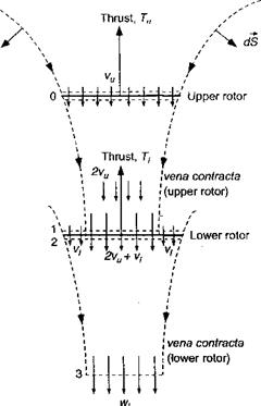
This simple momentum analysis of the problem has been shown to be overly pessimistic when compared with experimental measurements for closely spaced coaxial rotors – see Harrington (1951) and the review by Coleman (1993). The main reason for the overpre­diction of induced power is related to the actual (finite) spacing between the two rotors. Generally, on coaxial designs the rotors are spaced sufficiently far apart that the lower rotor operates in the vena contracta of the upper rotor. This is justified from the flow vi­sualization results of Taylor (1950), for example. Based on ideal flow considerations, this

Other Applications of the Momentum Theory

Figure 2.27 Flow model for a coaxial rotor analysis, where the lower rotor is considered to operate in the fully developed slipstream of the upper rotor.

means that only half of the area of the lower rotor operates in an effective climb velocity induced by the upper rotor.

This problem can be tackled by means of the simple momentum theory and the application of the mass, momentum, and energy conservation equations in integral form. We will assume that the performance of the upper rotor is not influenced by the lower rotor. The induced velocity at the upper rotor is

= ^ = (2.150)

where A is the disk area and T is the thrust on the upper rotor. The vena contracta of the upper rotor is an area of A/2 with velocity 2vu. Therefore, at the plane of the lower rotor there is a velocity of 2vu + Vi over the inner one-half of the disk area – see Fig. 2.27.

Over the outer one-half of the disk area, the induced velocity is V[. Assume that the velocity in the fully developed slipstream of the lower rotor (plane 3) is uniform with velocity wi. The mass flow rate through the upper rotor is pAvu, so that the momentum exiting in the slipstream of the upper rotor is (pAvu)2vu =2pAv%. This is the momentum of the fluid into the lower rotor. The mass flow rates over the inner and outer parts of the lower rotor are p(A/2)(2vu + V[) and p{A/2)vi, respectively. Therefore,

The momentum flow out of plane 3 is mw/, so the thrust on the lower rotor is Ti = pA(vu + Vi) wi – 2pAv2u.

Подпись: (2.152) (2.153) Подпись: (2.154) (2.155) (2.154) 2.155 and (2.157) (2.158) The work done by the lower rotor is
Pi = Tiivu + vt),

and this is equal to the gain in kinetic energy of the slipstream. Therefore,

1 , 1 fA

Ti(vu – f-vt) = – pA(vu + vi) wi ~ 2Pl) (2v“K2l)u

= ^pA(vu + vi)wf – 2pAv3u.

Assuming Ti — Tu = T, then T = 2pAv^, then from Eq. 2.152 we get

Tt = T = ]^pA(vu + vi)wi, and from Eq. 2.154 we get

T(2vu + vi) = ~pA(vu + vi)wf.

Using Eqs. 2.155 and 2.156 gives wt = 2vu + t’/ and substituting this into Eq. remembering that T = 2pAv^ gives

4pAv = pA (vu + vi) W[ = pA (vu 4- vt) (2vu + vt).

Rearranging as a quadratic in terms of vi and solving gives

Подпись: vu = 0.5616u„.-3 + VI7′

vi =

Other Applications of the Momentum Theory Подпись: 2.5616T Vh 2Tvh Подпись: 1.281, Подпись: (2.159)

The power for the upper rotor is Pu = Tvu = Tvh and for the lower rotor Pi = T{vu + v{) = 1.5616Tvh. Therefore, for both rotors the total power is 2.5616ГVh – This is compared to 2T Vh when the rotors are operating in isolation. This means that the induced power factor from interference, /c;nt, is given by

Подпись: K"int
Подпись: 2 Pu (Tu + Ti)vu Подпись: 1.281, Подпись: (2.160)
Other Applications of the Momentum Theory

which is a 28% increase compared to a 41% increase when the two rotors have no vertical separation (see Questions 2.19 and 2.20). This is closer to the values deduced from ex­periments for which Kmt ^ 1.16 [see, for example, Dingeldein (1954)] but the theory still overpredicts the interference value. When the coaxial is operated at equal rotor torque (see Question 2.20), it can be shown that the induced power factor is given by

which is the same result as for the thrust balanced case when compared to two isolated rotors operated at the same thrust. When compared to two isolated rotors at the thrusts needed for a torque balance, then /c;nt = 1.266.

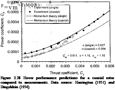
Figure 2.28 shows the power versus thrust relationship of single and coaxial rotors operating in hover; the measurements are taken from Harrington (1951) and Dingeldein

Other Applications of the Momentum Theory Подпись: (2.161)

(1954). The corresponding plot of figure of merit versus Ct/o is shown in Fig. 2.29. The power for the single two-bladed rotor was calculated from momentum theory using

Other Applications of the Momentum Theory Подпись: (2.162)
Other Applications of the Momentum Theory

and for the coaxial using

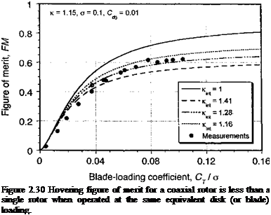
with к = 1.15 and к-ш = 1.16. The agreement between momentum theory and the mea­surements is good and confirms that the coaxial rotor operates as two isolated rotors but with an interference effect accounted for by /qnt. In this case the performance of both the single and coaxial rotors is stall-limited because of their relatively low solidity and also the lower blade chord Reynolds numbers at this reduced tip speed test (see Chapter 7), but the momentum theory shows what would be possible if stall was not present. Clearly the coaxial achieves a somewhat lower maximum figure of merit compared to a single rotor, all other factors being equal (i. e., when compared at the same disk loading, solidity and tip speed).

To properly compare the relative efficiency of a single and coaxial rotor system they must be compared at the same equivalent disk loading, that is, each rotor operates at the same approximate value of Т/ A (or Ст/сг for a given radius and tip speed). Under these conditions the figure of merit of the coaxial can be written as

where Kmt = 1 f°r an isolated single rotor. Because the lower rotor of a coaxial operates in the slipstream of the upper rotor its net induced velocity is always higher for a given value

0.

Other Applications of the Momentum Theory

8 –

Подпись: Figure 2.30 Hovering figure of merit for a coaxial rotor is less than a single rotor when operated at the same equivalent disk (or blade) loading.

of thrust and /Cjnt > 1 (where the values of icmt depend on the assumptions made) and so the net system efficiency is lower. Representative results are shown in Fig. 2.30 where it is clear that at a typical operating state the FM for a coaxial when operated at the same blade loading coefficient is related approximately to the corresponding FM of a single by a factor Kint. Other physical factors that seem to affect coaxial rotor performance include a thrust recovery effect through the removal of swirl losses in the downstream wake, although this effect seems only important at very high values of disk loading such as used on propellers. See also Andrew (1981), Saito & Azuma (1981), and Zimmer (1985) for more details on coaxial rotor performance.