Category Principles of Helicopter Aerodynamics Second Edition

Induced Inflow Ratio

The induced inflow velocity, iy, at the rotor disk can be written as

Vh = Vi = Xh&R, _ (2.25)

where the nondimensional quantity X^ is called the induced inflow ratio in hover. The angular or rotational speed of the rotor is denoted by Q and R is the rotor radius; so the product is simply the tip speed, Vtjp, which is also sometimes given the symbol V^r. The inflow ratio is normally the preferable quantity to use when comparing results from different rotors because it is a nondimensional quantity. For rotating-wing aircraft, it is the convention to nondimensionalize all velocities by the blade tip speed in hovering flight (i. e., by Vtip = &R = VnR).

2.3 Thrust and Power Coefficients

Like all branches of engineering, nondimensional coefficients are normally em­ployed in helicopter rotor analysis. Consider the induced velocity, vt, through the rotor. This can be written in functional form in terms of rotor thrust T, a reference area A such as disk area, a reference velocity V such as blade tip speed Vtip, and the density of the flow p using

Vi = fi(T, A, Vtip, P) or f2(T, A, Vtip, P, Vi) = 0. (2.26)

According to the Buckingham П method of dimensional analysis [see Anderson (2001)] this means there are five variables (N = 5), three fundamental dimensions (К = 3, namely: mass,

length, and time) and N — К = 2 or two П products. The functional dependence can, there­fore, be written in the form

/з(ПьП2) = 0, – (2.27)

p-‘A’lVtr2T =

MV2,

Подпись: Пі Подпись: = Cj, Подпись: (2.28)

where Пі and П2 are nondimensional groupings. Choosing the variables p, A, and VtjP as repeating variables (which are all linearly independent) the two nondimensional П products can each be written in terms of these repeating variables plus one other variable. Making each grouping dimensionally homogeneous, the first П product can be written as

which is a thrust coefficient. The second П product becomes

Induced Inflow Ratio

which is an inflow coefficient. This means that

Подпись: Vi QR Подпись: 1 / T QRV2pA Подпись: T 2pA(QR)2 Подпись: (2.32)
Induced Inflow Ratio

where the reference area is the rotor disk area A and the reference speed is the blade tip speed, QR. This definition follows the one used by Glauert (1935). All velocity components are nondimensonalized by tip speed so the inflow ratio X,- is related to the thrust coefficient in hover by

Подпись: CP Induced Inflow Ratio Подпись: (2.33)
Induced Inflow Ratio

This is based on the 1-D flow assumption made in the preceding analysis, which means that this value of inflow is assumed to be distributed uniformly over the disk. The rotor power coefficient is defined as

so that based on momentum theory the power coefficient for the hovering rotor is

Cp pA(ftR)3 (pA(QR)2) (ftf?) Сткі V2‘ (2‘34)

Again, this is calculated on the basis of uniform inflow and no viscous losses, so is called the ideal power coefficient. The corresponding rotor shaft torque coefficient is defined as

Подпись: (2.35)6^6
pAV2RR pAQ2R2′

Notice that because power is related to torque by P = QQ, then numerically Cp = Cq.

It is important to note that the US customary definition of the thrust, torque, and power coefficients is different to that used in some parts of the world (mainly in Britain, most of Europe, and Russia), where a factor of one half is used in the denominator giving

TO P

CT = —————- -, CQ = ———————– , and CP = ————————- -. (2.36

pA{&R)2 У ipA(£2R)2R ±pA(QR)3

This means that the values of thrust, torque, and power coefficients are all a factor of 2 greater than the values obtained with the US customary definition. The US definitions in Eqs. 2.31, 2.33, and 2.35 are used throughout this book.

Disk Loading and Power Loading

A parameter used frequently in helicopter analysis that appears in the preceding equations is the disk loading, T/A, which is denoted by DL. Because for a single rotor helicopter in hover, the rotor thrust, T, is equal to the weight of the helicopter, W, the disk loading is sometimes written as W/ A or W/nR2. Disk loading is measured in pounds per square foot (lb fir2) in British (Imperial) units or newtons per square meter (N m~2) in the SI system. One may also use kilograms per square meter (kg m~2) in the SI system. The direct use of the kilogram (kg) as a unit of force is frequently found in engineering practice, particularly in the aerospace field. For the purposes of computing the disk loading for multi-rotor helicopters such as tandems and coaxials, or for tilt-rotors, the convention is to assume that each rotor carries an equal proportion of the aircraft’s weight. Values of rotor disk loading for a selection of rotating-wing aircraft are given in the appendix.

The power loading is defined as T / P, which is denoted by PL. Power loading is measured in pounds per horsepower (lb hp-1) in Imperial units, or newtons per kilowatt (N kW-1) or kilograms per kilowatt (kg kW-1) in the SI system. Remember that the induced (ideal) power required to hover is given by P — Tvn. This means that the ideal power loading will be inversely proportional to the induced velocity at the disk. To see this, recall that the inflow velocity at the disk vt can be written in terms of the disk loading as

Disk Loading and Power Loading(2.24)

Disk Loading and Power Loading Disk Loading and Power Loading Подпись: 10

According to Fig. 2.6, the ratio T/P decreases quickly with increasing disk loading (note the logarithmic scale on the abscissa). Therefore, vertical lift aircraft that have a low ef­fective disk loading will require relatively low power per unit of thrust produced (i. e., they will have high ideal power loading) and will tend to be more efficient; that is, the rotor will require less power (and consume less fuel) to generate any given amount of thrust. Calcu­lation of the actual power loading and rotor efficiency, however, requires the consideration of viscous losses.

Figure 2.6 Hovering efficiency versus disk loading for a range of vertical lift aircraft.

Helicopters operate with low disk loadings in the region of 5 to 10 lb fir2 or 24 to 48 kg m-2, thus they can provide a large amount of lift for a relatively low power with a power loading up to 5 kg kW^1 (50 N kW_1 or 10 lb hp_1). Figure 2.6 shows that the helicopter is a very efficient aircraft in hover compared to other vertical takeoff and landing (VTOL) aircraft. Tilt-rotors can be considered a hybrid helicopter/fixed-wing aircraft and have higher rotor disk loadings. Therefore, they are less efficient in hover than a conventional helicopter of the same gross weight but still are much more efficient than other VTOL aircraft without rotating wings.

Pressure Variation

The pressure variation through the rotor flow field in the hover state can be found from the application of Bernoulli’s equation along a streamline above and below the rotor disk. Remember that there is a pressure jump across the disk as a result of energy addition by the rotor, so that Bernoulli’s equation cannot be applied between points in the flow across the disk. But the pressure jump is uniform over the rotor disk so the equation can be applied to all streamlines contained within the control volume. For incompressible flow, the Bernoulli equation is an alternative to the energy equation (one of the two is redundant). Applying Bernoulli’s equation up to the disk between stations 0 and 1 produces

Подпись:PO = Poo = Pi + ^pvf.

Below the disk, between stations 2 and oo, the application of Bernoulli’s equation gives

Подпись: (2.19)1 2 1 2 P2 + 2PVi = Poo + £Pw

Because the jump in pressure Ap is assumed to be uniform across the disk, this pressure jump must be equal to the disk loading, T/А, that is,

T

Ap = P2~Pi = — • (2.20)

A

Therefore, we can write

T f 1 2 1 Л / 1 Д 1 2

д = P2 – P – I Poo + – pw – – pvt I – I Poo – – pvt 1 = – pw, (2.21)

Pressure Variation

from which it is seen that the rotor disk loading is equal to the dynamic pressure in the vena contracta. One ean also determine the pressure just above the disk and just below the disk in terms of the disk loading. Just above the disk the use of Bernoulli’s equation gives

and just below the disk we get

1 2 1 /w2 3 ST

P2 = PO + ^pw – – p{–) = P0 + ? (-) . (2.23)

Therefore, the static pressure is reduced by (T/A) above the rotor disk and increased by |(Г/A) below the disk.

Induced Velocity and Rotor Power

It has been shown previously using Eq. 2.7 that momentum theory can be used to relate the rotor thrust to the induced velocity at the rotor disk by using the equation

T = mw — m(2vi) = 2(pAvi)Vi = 2pAvf. (2.14)

Rearranging this equation and solving for the induced velocity at the plane of the rotor disk gives

= = Ш5)

The ratio T/ A is known as the disk loading, which is an extremely important parameter in helicopter analysis. Notice that vh == щ is used to represent the induced velocity in hover. This value will be used later as a reference when the axial climb and descending flight conditions are considered.

The power required to hover (or the time rate-of-work done by the rotor on the fluid per unit thrust) is given by

nr t3/2

P = Ты = Tvh = ТІ————— = ———– . (2.16)

V 2pa rr

This power, called ideal power, is entirely induced in nature because the contribution of viscous effects have not been considered in the present level of analysis. Alternatively, we can write

Подпись: (2.17)P = Tvi = 2 rhvf = 2(pAvi)vf = 2pAv.

From this equation it is noted that the power required to hover will increase with the cube of the induced velocity (or inflow) at the disk. Obviously, to make a rotor hover at a given thrust with minimum induced power, the induced velocity at the disk must be small. Therefore, the mass flow through the disk must be large and this consequently requires a large rotor disk area. This is a fundamental design feature of all helicopters.

Application to a Hovering Rotor

These general equations of fluid mass, momentum, and energy conservation may now be applied to the specific problem of a hovering helicopter rotor. The procedures are basically those attributed to Rankine and Froude, as generalized by Glauert (1935) and adopted by others, including Johnson (1980). In Fig. 2.5 let cross section 0 denote the plane far upstream of the rotor, where in the hovering case the fluid is quiescent (i. e., Vo = 0). The rotor disk area is denoted by A. Cross sections 1 and 2 are the planes just above and below the rotor disk, respectively, and the “far” wake[11] is denoted by cross section oo. At the plane of the rotor, assume that the velocity (the induced velocity or velocity imparted to the mass of air contained in the control volume at the rotor disk) is vt. In the far wake

(the vena contracta), the velocity will be increased over that at the plane of the rotor and this velocity is denoted by w.

From the assumption that the flow is quasi-steady and by the principle of conservation of mass, the mass flow rate, m, must be constant within the boundaries of the rotor wake (control volume). Therefore, the mass flow rate is

rh = /f (2-4)

and the 1-D incompressible flow assumption reduces this equation to

m = pAooW = pA2Vi = pAvi. (2.5)

The principle of conservation of fluid momentum gives the relationship between the rotor thrust, T, and the net time rate-of-change of fluid momentum out of the control volume (Newton’s second law). The rotor thrust is equal and opposite to the force on the fluid, which is given by

-F = T = ff p{V ■ dS)V – ff p{V ■ dS)V. (2.6)

J J oo J Jo

Application to a Hovering Rotor Подпись: (2.7)

Because in hovering flight the velocity well upstream of the rotor is quiescent, the second term on the right-hand side of the above equation is zero. Therefore, for the hover problem, the rotor thrust can be written as the scalar equation

From the principle of conservation of energy, the work done on the rotor is equal to the gain in energy of the fluid per unit time. The work done per unit time, or the power consumed by the rotor, is T u, and this results in the equation

Application to a Hovering Rotor(2.8)

In hover, the second term on the right-hand side of the above equation is zero so that

Подпись: (2.9)Tvi = If – p(V ■ dS)Vz = – raw2. J J oo 7 2

From Eqs. 2.7 and 2.9 it is clear that

Application to a Hovering Rotor(2.Ю)

or that w = 2Vi. This, therefore, gives a simple relationship between the induced velocity in the plane of the rotor, u, , and the velocity w in the vena contracta.

Rotor Slipstream

Because the flow velocity increases in the wake below the rotor, continuity con­siderations require that the area of the slipstream must decrease. This is apparent from the empirical observations in Figs. 2.2 and 2.4. It follows from the conservation of fluid mass between the rotor and the vena contracta that

Подпись:pAvi = pAooW = pA^ilvi) = IpAooVi,

so that in hover the ratio of the cross-sectional area of the fully developed far wake to the area of the rotor disk is

Подпись: (2.12)-^OO 1

~A ~2

Application to a Hovering Rotor Подпись: (2.13)

In other words, based on ideal fluid flow assumptions, the vena contracta is an area that is exactly half of the rotor disk area. Alternatively, by considering the radius of the far rotor wake, Гоо, relative to that of the rotor, R, it is easy to show from mass conservation considerations that

Therefore, the ratio of the radius of the wake to the radius of the rotor is 1 /V2 = 0.707. This is called the wake contraction ratio. In practice, it has been found experimentally that the wake contraction ratio is not as much as the theoretical value given by the momentum theory; typically it is only about 0.78 compared to 0.707. This is mainly a consequence of the viscosity of the fluid, the reality that a nonuniform inflow will be produced over the disk and a small swirl component of velocity in the rotor wake induced by the spinning rotor blades. Behaviors directly attributable to the viscosity of the fluid are termed nonideal effects, and these will be considered in detail later.

Conservation Laws of Aerodynamics

In the general approach to the problem, it will be assumed that the flow through the rotor is one-dimensional, quasi-steady, incompressible and inviscid. Consider first an ideal fluid, that is, one that generates no viscous shear between fluid elements. Therefore, induced losses are the sole source of losses in the fluid, with other losses resulting from the action of viscosity being assumed negligible, at least for now. Furthermore, assume that the flow is quasi-steady, in that the flow properties at a point do not change with time. Finally, assume that the flow is one-dimensional, and so the properties across any plane parallel to the rotor plane are constant; that is, the fluid properties change only with axial (vertical) position relative to the rotor.

Consider the hover problem. Let the control volume surrounding the rotor and its wake have surface area S, as shown in Fig. 2.5. Let dS be the unit normal area vector (i. e., the outward facing normal), which by convention always points out of the control volume across the surface S. A general equation governing the conservation of fluid mass applied to this finite control volume can be written as

Подпись:Conservation Laws of Aerodynamics(2.1)

where V is the local velocity and p is the density of the fluid. This equation states that the mass flow into the control volume must equal the mass flow out of the control volume. Notice that this is a scalar equation. Similarly, an equation governing the conservation of fluid momentum can be written as

Подпись: (2.2)

Conservation Laws of Aerodynamics Подпись: (2.3)

For an unconstrained flow, the net pressure force on the fluid inside the control volume is zero. This point has been considered by Glauert (1935), although it is not so obvious. Therefore, the net force on the fluid, F, is simply equal to the rate of change with time of the fluid momentum across the control surface, S. Although Eq. 2.2 is a vector equation, it can be simplified considerably by the assumptions of quasi-one-dimensional flow. This is essentially a byproduct of assuming a uniform pressure jump over the rotor disk and leads to uniform distributions of velocity across any horizontal cross section within the control volume. Because the force on the fluid is supplied by the rotor, by Newton’s third law the fluid must exert an equal and opposite force on the rotor. This force is the rotor thrust, T. Finally, an equation governing the conservation of energy in the flow can be written as

This equation states simply that the work done on the fluid by the rotor manifests as a gain in kinetic energy of the fluid in the rotor slipstream per unit time. It is also a scalar equation.

Flow Near a Hovering Rotor

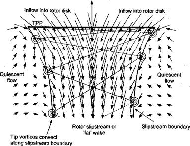
Hover is a very unique flight condition. Here, the rotor has zero forward speed and zero vertical speed (no climb or descent). The rotor flow field is, therefore, azimuthially axisymmetric. A set of velocity measurements near a subscale hovering rotor and in its wake is shown in Fig. 2.4. Notice that the fluid velocity is increased smoothly as it is entrained into and through the rotor disk plane. There is no jump in velocity across the disk, although because a thrust is produced on the rotor, there must be a jump in pressure over the rotor disk. The existence of a wake boundary or slipstream is apparent, with the flow velocity outside this boundary being relatively quiescent. The blade tip vortices trail behind and below each blade and are convected along this wake boundary. Inside the wake boundary, the flow velocities are substantial and may be distributed nonuniformly across the slipstream. Note also the contraction in the diameter of the wake below the rotor corresponding to an increase in the slipstream velocity.

Rotor thrust

Flow Near a Hovering Rotor

Figure 2.4 Measurements of the velocity field in a diametric plane near and below a two-bladed rotor operating in hover. Data source: Leishman et al. (1995)

With the physical picture of the hovering rotor flow now apparent, it is possible to approach a mathematical solution to this problem. Consider the application of the three basic conservation laws (conservation of mass, momentum, and energy) to the rotor and its flow field. The conservation laws will be applied in a quasi-one-dimensional integral formulation to a control volume surrounding the rotor and its wake. This approach permits us to perform a first level analysis of the rotor performance (e. g., its thrust and power), but without actually having to consider the details of the flow environment, that is without having to consider what is happening locally at each blade section. This approach, which is called momentum theory, was first developed by Rankine (1865) for use in the analysis of marine propellers. The theory was developed further by W. Froude (1878) and R. E. Froude (1889), Lanchester (1915), and Betz (1920a, b; 1922). Momentum theory was formally gen­eralized by Glauert (1935) – see entry in Durand (1935). The main difference between the Froude and Rankine theories is in the treatment of the rotor disk as a series of elementary rings, versus the treatment of the disk as a whole. In either case, one fundamental assump­tion in the basic momentum theory is that the rotor can be idealized as an infinitesimally thin actuator disk over which a pressure difference exists. The concept is equivalent to considering an infinite number of blades of zero thickness, a concept first suggested by W. Froude. The actuator disk supports the thrust force that is generated by the rotation of the rotor blades about the shaft and their action on the air. Power is required to generate this thrust, which is supplied in the form of a torque to the rotor shaft. Work done on the rotor leads to a gain in kinetic energy of the rotor slipstream and this is an unavoidable energy loss that is called induced power.

Momentum Theory Analysis in Hovering Flight

The helicopter, or any other rotating-wing vehicle, must operate in a variety of flight regimes. These include hover, climb, descent, or forward flight. In addition, the helicopter may undergo maneuvers, which may comprise a combination of these basic flight regimes. In hover or axial flight, the flow is axisymmetric and the flow through the rotor

is either upward or downward. This is the easiest flow regime to analyze and, at least in principle, it should be the easiest to predict by means of mathematical models. It has been found, however, that even with modern mathematical models of the rotor flow, accurate prediction of hovering performance is by no means straightforward. Although it must be remembered that the actual physical flow about the rotor will comprise a complicated vortical wake structure, as previously shown in Fig. 2.2, the basic performance of the rotor can be analyzed by a simpler approach that has become known as the Rankine-Froude momentum theory. The momentum theory approach allows the derivation of a first-order prediction of the rotor thrust and power, and the principles also form a foundation for more elaborate treatments of the rotor aerodynamics problem.

Fundamentals of Rotor Aerodynamics

The essential theory of flight can be reduced to a comparatively simple statement, though it becomes a highly complicated affair as it is presented in figures and formulae.

Juan de la Cierva (1931)

2.1 Introduction

Advances in the understanding of helicopter aerodynamics has led to many gains in helicopter performance compared to even just two decades ago. In most cases, the under­standing of the various aerodynamic problems have been approached using analytic theories, numerical modeling, and experimentation, which have worked in conjunction with develop­ments in other disciplines to advance the better understanding of the helicopter as a whole. The rotor of a helicopter provides three functions: 1. The generation of a vertical lifting force (thrust) in opposition to the helicopter’s weight; 2. The generation of a horizontal propulsive force for forward flight; and 3. A means of generating forces and moments to control the attitude and position of the helicopter in three-dimensional space. All three of these functions must be under the full control of the pilot. Unlike a fixed-wing aircraft where these functions are separated, the helicopter rotor alone must provide all three functions. To meet these demanding roles, the rotor designer requires considerable knowledge of both the aerodynamic environment in which the rotor operates, as well as how the aerodynamic loads affect the dynamic response of the flapping blades and the overall rotor behavior.

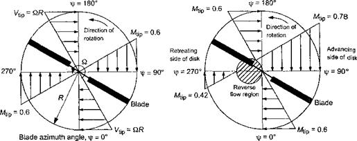
The lifting capability of any part of a rotating blade is related to its local angle of attack (AoA) and local dynamic pressure. The blade position can be defined in terms of an azimuth angle, т/г, which is defined as zero when the blade is pointing downstream, as shown in Fig. 2.1. In hovering flight, Fig. 2.1(a) shows that the velocity variation along the blade is azimuthally axisymmetric and radially linear, with zero flow velocity at the rotational axis and the velocity reaching a maximum, Vtjp, at the blade tip. The local dynamic pressure at any blade element is proportional to the square of the distance from the rotational axis. Based on elementary considerations, for a constant blade AoA, the average rotor thrust will depend on the square of the rotor tip speed, Vtip = fi/?, that is Г a Vj? . Also, the rotor power, P, will depend on the cube of the tip speed, that is P oc VJ_ (see Question 2.1),

In forward flight, a component of the free stream, Voo> adds to or subtracts from the rotational velocity at each part of the blade, that is, Viip now becomes QR+Yqq sin ifs. As shown by Fig. 2.1(b), while the distribution of velocity along the blade remains linear, it is no longer axisymmetric and varies in magnitude with respect to blade azimuth angle. It will also be evident that forward flight speed, blade pitch angle and any blade flapping, as well as the distribution of induced inflow through the rotor, will all affect the blade section AoA and, therefore, the blade lift distribution, rotor thrust, and rotor power consumption. This nonuniformity of the AoA over the rotor disk is the complication with the helicopter rotor that makes its aerodynamic analysis difficult.

I Vx= 0.3 QR

Fundamentals of Rotor Aerodynamics

(a) Hovering flight (b) Forward flight, ц = 0.3

Figure 2.1 Distribution of incident velocity normal to the leading edge of the rotor blade, (a) Hovering flight, (b) Forward flight at /t = 0.3.

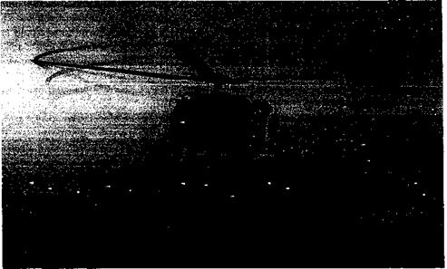
Unlike on a fixed-wing, which has a relatively uniform lift loading over its span, the high dynamic pressure found at the tips of a helicopter blade produces a concentra­tion of aerodynamic forces there. As a consequence, strong vortices form and trail from each blade tip. Figure 2.2 shows an example of the physical nature of the vortical wake generated by a helicopter rotor in hovering flight (see also Figs. 1.38,10.1, and 10.2). Here, the blade tip vortices are rendered visible by natural condensation of water vapor in the

Fundamentals of Rotor Aerodynamics

Figure 2.2 Hovering helicopter showing the vortical rotor wake through natural conden­sation of water vapor inside the tip vortex cores. (Courtesy of the US Navy, Patuxent River Navel Air Station.)

air. These vapor trails are only obtained under conditions when the air temperature is close to the dew point; it is produced by the small amount of cooling that takes place inside the low pressure vortex cores. It will be seen that the vortices are convected downward below the rotor and form a series of interlocking, almost helical trajectories. For the most part, the net flow velocity at the plane of the rotor and in the rotor wake itself is comprised of the velocities induced by these tip vortices. For this reason, predicting the strengths and locations of the tip vortices (see Chapter 10) plays an important role in determining blade airloads and rotor performance, as well as in designing the blades and rotor as a system.

All helicopters spend considerable time in hover, which is a flight condition where they are specifically designed to be operationally efficient. In hover, the main purposes of the rotor are to provide a vertical lifting force in opposition to the weight of the helicopter and flight control. However, in forward flight the rotor must also provide a propulsive and force to overcome the drag of the helicopter. This is obtained by tilting the plane of the rotor forward, while increasing the overall rotor thrust so that that the vertical compo­nent of thrust (lift) remains equal to the aircraft weight. In forward flight the rotor blades encounter an asymmetric velocity field, which is a maximum on the blade that advances into the relative wind and a minimum on the blade that retreats away from the relative wind [see Fig. 2.1(b)], The local dynamic pressure and the blade airloads, therefore, be­come periodic primarily at the rotational speed of the rotor (i. e., once per revolution or 1/rev). Because of the articulation built into helicopter blade designs, the rotor blades will begin to flap about their hinges causing the rotor disk to tilt. This inherent tendency can be compensated for by the pilot by using appropriate cyclic pitch inputs to the blades. This changes the magnitude and phasing of the 1/rev aerodynamic lift forces over the disk, and so it can be used to maintain a desirable orientation of the rotor disk to meet propulsion and flight control requirements. The inherent coupling among blade pitch in­puts, the aerodynamic forces and the blade flapping response is discussed in detail in Chapter 4.

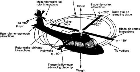
The overall aerodynamic complexity of the helicopter in forward flight can be appreci­ated from Fig. 2.3. The flow field in which the rotor operates is considerably more complex

Complex vortex wake structure

Fundamentals of Rotor Aerodynamics

Figure 2.3 Schematic showing the flow structure and some aerodynamic problem areas on a helicopter in forward flight.

than that of a fixed-wing aircraft, mainly because of the individual wakes trailed from each blade. For a fixed-wing aircraft, the wing wake and tip vortices trail downstream of the aircraft. However, for a helicopter in forward flight, the blade tip vortices can remain close to the rotor and to following blades for several rotor revolutions. As a result of the low disk loading (thrust carried per unit area of the rotor disk) and generally low aver­age flow velocity through the rotor disk, these vortices remain close enough to produce a strongly three-dimensional induced velocity field. As following blades encounter this in­duced velocity field, fluctuating airloads are produced on the blades.[10] Besides affecting the rotor performance, these time-varying airloads can be a source of high rotor vibrations and strongly focused obtrusive noise.

At higher forward flight speeds, the inherently asymmetric nature of the flow over the rotor disk gives rise to a number of aerodynamic problems that ultimately limit the rotor performance. The most obvious is that the blade tips on the advancing side of the rotor disk can start to penetrate into supercritical and transonic flow regimes, with the associated formation of compressibility zones and, ultimately, strong shock waves. In addition to the occurrence of wave drag and the possibilities of shock induced flow separation, both phenomena require much more power to drive the rotor, the periodic formation of shock waves is another source of obtrusive noise. The increased power demands placed on the rotor system, when compressibility effects manifest, will eventually limit forward flight speeds. Although compressibility effects on contemporary rotors can be relieved to some extent by the use of swept tip blades and thin “transonic” airfoils, the problems of increased power requirements and noise are only delayed to moderately higher forward flight speeds and are not eliminated.

On the retreating side of the disk, that is, where the blades are retreating away from the relative wind because of the forward night velocity of the helicopter, the local velocity and dynamic pressure at the blade are relatively low and the blades are required to operate at higher AoA to maintain lift. If these values of AoA become too large, then the retreating blade will stall. This results in a loss of overall lifting and propulsive capability from the rotor and sets an intrinsic barrier to further increases in forward flight speed. It is interesting to note that while stall on a fixed-wing aircraft occurs at low flight speeds, a helicopter encounters the problem of stall at relatively high flight speeds. Because of the inherent time-dependent nature of the flow environment on the rotor blades in forward flight, re­treating blade stall is highly unsteady in nature and is referred to as dynamic stall (see Chapter 9). The unsteady airloads produced during dynamic stall are an additional source of vibration on the helicopter, which can significantly limit its forward flight and maneu­vering capability. The various aerodynamic interactions that can exist between the rotor wake and the airframe, including the tail rotor and empennage, are also worthy of note (see Fig. 2.3). Although fundamentally complicated, these interactions can lead to various signif­icant aerodynamic interference effects that cannot be ignored in the design of the helicopter. These issues are discussed in Chapter lx.

Compounds, Tilt-Wings, and Tilt-Rotors

The conventional helicopter is limited in forward flight performance by the aero­dynamic lift and propulsion limitations of the main rotor. These rotor limits arise because of compressibility effects on the advancing blade, as well as stall on the retreating blade (see page 57). In addition, the relatively high parasitic drag of the rotor huh and other airframe components leads to a relatively poor overall lift-to-drag ratio of the helicopter (less than 6). This generally limits performance of conventional helicopters to level-flight cruise speeds in the range of 150 kts (278 km/h; 172 mi/li), with dash speeds up to 200 kts (370 km/h; 230 mi/h) and unrefueled ranges of less than 500 miles. Although somewhat higher flight speeds are possible with compound designs, which use auxiliary propulsion devices and wings to offload the rotor, this is always at the expense of much higher power required and fuel bum than would be necessary with a fixed-wing aircraft of the same gross-weight and cruise speed. One example of a revolutionary compound helicopter was the Lockheed AH-56 Cheyenne, which was built in 1969 – see Fig. 1.39. This machine used both lift compounding with a wing and propulsion compounding using a pusher propeller. It flew at over 220 kts (407.77 km/h; 253.4 mi/h). It did not, however, go into production – see Forman (1996).

Подпись: Figure 1.39 The Lockheed AH-56 Cheyenne was a revolutionary compound helicopter. (Photo courtesy of AHS.)
Compounds, Tilt-Wings, and Tilt-Rotors

The need for an aircraft that could combine the benefits of a vertical takeoff and landing (VTOL) capability with the high speed cmise of a fixed-wing aircraft has led to the evolution of tilt-wing and tilt-rotor concepts. A good history of the many VTOL designs, including tilt-wings and tilt-rotors, is given by Hirschberg (1997). However, this potential capability

comes at an even greater price than for either a conventional or compound helicopter, including increased mechanical complexity, increased weight and the susceptibility for the rotors and wing to exhibit various aeroelastic problems.

The tilt-wing is basically a convertiplane concept, but it never became a viable rotating – wing concept to replace or surpass the capabilities of the helicopter. The idea is that the wing can be tilted from its normal flying position with the propellers providing forward thrust, to a vertical position with the propellers providing vertical lift. Several companies seriously considered the tilt-wing concept in the 1950s, with Boeing, Hiller, Vought-Hiller – Ryan (later Ling-Temco-Vought) and Canadair all producing flying prototype aircraft. The Vertoi VZ-2 first flew in 1957 and went on to make many successful conversions from hover into forward flight. However, the unsteady airloads produced by airflow separation on the wing as it stalled during conversion flight resulted in some difficult piloting and these issues were never satisfactorily resolved. The Hiller X-18 was a large tilt-wing aircraft compared to the VZ-2. The aircraft used two large diameter counterrotating propellers (used from the earlier Ryan Pogo concept) – see Straubel (1964). The aircraft underwent flight testing in 1960, but never did make a full conversion. The program was canceled in 1961 after the aircraft suffered a loss of control. In the 1980s, the Ishida Company developed the TW-68 tilt-wing aircraft as a private venture, but the company went into bankruptcy before the aircraft could be built.

The tilt-rotor aircraft takes off and lands vertically with the rotors oriented like a heli­copter. For forward flight, the wing tip-mounted rotors are progressively tilted to convert the aircraft into something that looks like a fixed-wing turboprop airplane. In this mode, the tilt-rotor is able to achieve considerably higher flight speeds (about 300 kts; 555 km/h; 344 mi/h) than would be possible with a helicopter. Therefore, the tilt-rotor combines some attributes of the conventional helicopter with those of a fixed-wing aircraft. During WW2, the Focke Achgelis Fa 269 was proposed as a tilt-rotor. The side-by-side rotors pointed downward for takeoff and then rotated aft to provide propulsion in normal flight with con­ventional wings providing lift. However, the aircraft remained a paper project. A practical tilt-rotor concept was first demonstrated in a joint project between the Transcendental Air­craft Corporation and Bell in 1954. Various technical problems were encountered with the first aircraft, the Model 1 – G, especially in the conversion from helicopter mode to fixed-wing flight. Bell later led the development of the XV-3 in 1951, which had two fully articulated three-bladed rotors. The XV-3 was damaged in an accident in 1956 after an aeroelastic problem with the rotor. The second XV-3 used a two-bladed teetering rotor system and the aircraft was successfully flown in 1958. However, several aeromechanical problems were again encountered, including pylon whirl flutter.

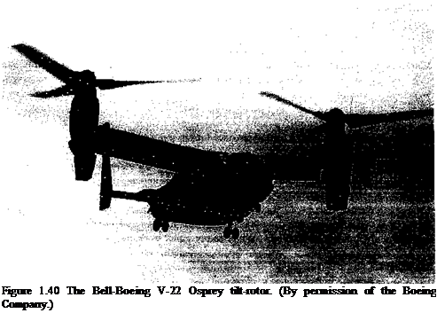
By the late 1960s, Bell had developed the Model 266 tilt-rotor and later the Model 300. Various wind-tunnel tests of scaled models led to an improved understanding of the rotor and wing aeroelastic issues involved with tilt-rotors, especially during the conversion mode and Bell continued to develop the Model 301, This aircraft later became the XV-15, which demonstrated the viability of the tilt-rotor concept. The XV-15 was purely experimental and never designed for production, and flew experimentally through 2003. However, in 1983 the much larger V-22 Osprey tilt-rotor program was begun (see Fig. 1.40). This joint Bell-Boeing project has resulted in several test and preproduction aircraft and in 1997 the decision was made to put the aircraft into production for the US Marines, Navy, and Air Force. As of 2005, however, it was still in the developmental stage with low rate production. Because the rotors of a tilt-rotor cannot be as large as those of a helicopter, the hovering efficiency of the tilt-rotor is not as good as that of a helicopter. In the design of the Bell – Boeing V-22 Osprey, the rotor diameter was also limited by the need to operate and hangar
the aircraft on board an aircraft carrier. The tilt-rotor, however, has the ability to fly much faster than a conventional helicopter.

The Agusta-Bell Model 609 civilian tilt-rotor first flew in 2003 and will be capable of transporting 9 passengers at 275 kts (509 km/h; 315 mi/h) over 750 nm (1,390 km; 860 mi) sectors. It is expected to be certified in 2007. See Bell Helicopter Textron (2005) for further information. The Europeans too have embarked on fundamental research toward a civil tilt-rotor program suited to scheduled passenger transport. The project is being undertaken by a consortium of twelve partners representing five European nations. The ultimate aim is to develop a 19-seat, twin-engine tilt-rotor aircraft that can be flown by a single pilot to be sold to airlines and corporations. While the work is expected to culminate in the first flight of the new tilt-rotor aircraft in 2008, the lengthy half-decade-long development of the American tilt-rotor program suggests that realistically the flights of a European tilt-rotor may be further away than this. The success of any civil tilt-rotor program, European or American, may be tied to the ultimate success or otherwise of the V-22 Osprey.

Подпись: 1.14

Подпись: Figure 1.40 The Bell-Boeing V-22 Osprey tilt-rotor. (By permission of the Boeing Company.)

РІіапІлг D airinnr V’liapiVl JLXV’TAVTT

During the past sixty years since the first successful flights, helicopters have ma­tured from noisy, unstable, rickety vibrating contraptions that could barely lift the pilot and a small payload into sophisticated machines of quite extraordinary capability. Igor Sikorsky’s dream has certainly been fulfilled, perhaps in many ways that he could not have possibly imagined. At the beginning of the twenty-first century, there were about 40,000 helicopters flying worldwide. Its roles encompass air ambulance, sea and mountain rescue, police surveillance, corporate services and oil rig servicing in the civilian world and troop transport and antitank gunships in military use. In rescue operations alone, the helicopter

has saved the lives of well over a million people. The helicopter today is a safe, versatile, and reliable aircraft and it will continue to be an indispensable part of modern life well into the twenty-first century.

The improved design of the helicopter and the increasing viability of other vertical lift aircraft such as the tilt-rotor continue to advance as a result of the revolution in computer – aided design and manufacturing and the advent of new lightweight composite materials. Sustained scientific research and development in many aeronautical disciplines has allowed for dramatic increases in helicopter performance, overall lifting and cruise efficiencies, and excellent mechanical reliability. Continuous aerodynamic improvements to rotor efficiency

Kni m ПІ1/МІГЛ/1 fli л ліі л t/л I – i ft n «л ілтгі /лп /4 tU«t m tv» /Л»*а tlv n «л ttr /vtv»»-»tt т fir/vt/vlvt ntv/4 – t-л

navu anuwLu mw liuiivupiui tv nit a pa^iuau uiat 10 mutt шсш на auu tv

fly in level flight at speeds in excess of 200 kts (370 km/h; 229 mi/h). Since the 1980s, there has been an accelerating scientific effort to understand and overcome some of the most difficult technical problems associated with helicopter flight, particularly in regard to aerodynamic limitations associated with the main rotor. In more recent years, however, increases in the capabilities of helicopters has been much more incremental, despite major advances in understanding using various types of computational aerodynamic methods and experimental measuring techniques. While future gains in performance will certainly be attained, the immediate need for more capable, efficient, safer, and economic helicopters centers on the ability to really understand and more accurately predict its aerodynamics. This may also require the implementation of revolutionary developments to control its complex aerodynamics. Only then will the helicopter fulfill a wider variety of civilian and military roles.