Category Principles of Helicopter Aerodynamics Second Edition

Maturing Technology

The early 1950s saw helicopters quickly maturing into safe, successful, and viable aircraft that were easier to fly and more comfortable for crew and passengers alike. This era is marked by significant mass production of helicopters by various manufacturers in the United States, Britain, France, and elsewhere. There were rapid strides in the development of turboshaft engines (Fig. 1.17), with continuous improvements in power output and specific fuel consumption, low weight and high mechanical reliability. This was also accompanied by reductions in the net cost of an engine per unit of power output. Thereafter, the helicopter was to become a wide-scale commercial success.

Maturing Technology

Figure 1.33 The Sikorsky S-55 was quantum-leap in terms of flight performance and payload capability for a single rotor helicopter. (Photo courtesy of Sikorsky Aircraft.)

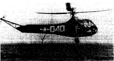
The Sikorsky S-55 (see Fig. 1.33) and the S-58 models made great advances in helicopter design. These aircraft sported a large cabin under the rotor and to give a wide allowable center of gravity position, the engine was placed in the nose. Westland also maintained their relationship with Sikorsky and built versions called the S-55 Whirlwind and S-58 Wessex. The 1960s saw the development of the Sikorsky S-61 Sea King, the HH-52 (S-62), the heavy-lift S-64 Sky Crane and the larger five – and seven-bladed CH-53 models. The HH-52 (S-62) is arguably one of the greatest lifesaving aircraft ever created – see Beard (1996). Later, the S-70 (UH-60) Blackhawk was to become the mainstay of the Sikorsky company and the machine is expected to remain in production well into the twenty-first century. The civilian S-76 has been successful in its role as an executive transport and air ambulance, amongst other roles. In the 1970s, Sikorsky and Boeing teamed to build the military RAH-66 Comanche (Fig. 1.34). While producing one of the most advanced combat helicopters ever built, this program was cancelled by the Pentagon in 2004. The latest Sikorsky machine, the civilian medium lift S-92 flew for the first time in 1998 and was certified in 2002. In 2005, Sikorsky proposed a series of coaxial rotor helicopters, ranging from small unmanned velicles to heavy-lifters. For more information, see Sikorsky Aircraft (2005).

The success with the Model-47 led Bell Helicopter to develop the UH-1 Huey, which was delivered starting in 1959. The Bell 212 was a two-engine development of the UH-1D and proved to be a successful military and civilian machine. The Huey-Cobra also grew out of the UH-1 series, retaining the same rotor components but having a more streamlined fuselage with the crew seated in tandem. First flown in 1966, the type was in production in 1999 as the AH-1W Super-Cobra, which uses an advanced composite four-bladed rotor. The “Z” model is the current state of the art. The Bell 412 is basically a 212 model, but with a four-bladed composite rotor replacing the two-bladed teetering rotor. Bell led the civilian market with its Model 206 Jet-Ranger and variants, which first flew in 1966 and has become one of the most widely used helicopters. The OH-58 military version was sold in considerable numbers and with sustained performance improvements over the years,
with the OH-58D having an advanced four-bladed rotor with a mast-mounted sight. One of most recent civil variants is the Bell 427, which is an eight-place light twin. See also Bell Helicopter Textron (2005).

Hughes Aircraft built the military TH-55 and later the Hughes 500 series, which has seen extensive civilian use in various models. However, the AH-64 Apache, which was designed in 1976, proved to be the biggest success story for the Hughes company, which became part of McDonnell-Douglas in 1984 and finally part of Boeing in the late 1990s. The AH-64D Longbow model (Fig. 1.35) is still in production. It was also produced under license in Britain by Agusta-Westland, with sixty-seven helicopters being delivered to the British Army by 2004. McDonnell-Douglas have produced a line of light commercial helicopters including the MD 500 and 600 series, and most recently have marketed the MD 900 Explorer. This aircraft uses a new bearingless rotor design and the “No Tail Rotor” (NOTAR) circulation control anti-torque concept (see Section 6.10.2). In 1999 Boeing sold the commercial helicopter line to MD Helicopters, a subsidiary of a European company.

Подпись: kVl 111UUOV1 '

Подпись: Figure 1.34 The Boeing-Sikorsky RAH-66 Comanche, which first flew in 1996. (By permission of the Boeing Company.)

Although most medium – and heavy-lift helicopters are produced for the military, the civil market still has a substantial market share. Several manufacturers produce training and light – utility helicopters or helicopters aimed at the general aviation market, including Robinson, Schweizer, Rotorway, Brantley, and Enstrom. Robinson produces the highly successful R-22 two-seat and R-44 four-seat helicopters. Both models are powered by piston engines and their success has done much tO tum the civil helicopter industry aw. qv from the. trend

toward turbine engines. In 2004, nearly 80% of all helicopters built in North America were made by Robinson, who has substantially lowered the economic barriers for entry into the light-utility market. Schweizer, which as of 2004 became part of Sikorsky, produces an updated version of the two-seat Hughes 300 for the training market and a larger derivative designated as the Model-330, has a turboshaft engine.

European manufactures such as Aerospatiale and Messerschmitt-Bolkow-Blohm (MBB) (together they are now Eurocopter), Agusta, and Westland have produced many success­ful helicopter designs since the 1960s. Agusta and Westland have also license-produced

Maturing Technology

Figure 1.35 A version of the McDonnell-Douglas (now Boeing) AH-64 Apache. (By permission of the Boeing Company.)

helicopters designed in the United States, such as those of Sikorsky and Bell. The Aerospa­tiale (Sud-Aviation) Alouette II/III was one of the most successful European helicopters and in 1955 it was one of the first machines to be powered by a turboshaft engine. The Djinn (Genie) was the only mass-produced helicopter using a tip-jet design. The Aerospa­tiale Super Frelon was a large transport helicopter, first flown in 1962. In the early 1970s the Aerospatiale/Westland SA330 Puma became Europe’s best selling transport helicopter. The Aerospatiale/Westland Gazelle was a successful successor to the Alouette, first flown in 1967 and it introduced the fenestron tail rotor. The fenestron is a ducted tail rotor design, fully integrated into the fuselage and vertical fin and, like the NOTAR, essentially eliminates the all-too-common problem of tail rotor strikes. The Dauphin, first flown in 1972, used an improved fenestron tail rotor and a composite main rotor hub. MBB introduced the BO 105 in 1967 with a hingeless rotor, with the larger and more capable BK 117 machine first flying in 1979. In the 1990s, Aerospatiale and MBB joined resources to form Eurocopter, which produces a large range of civil and military helicopter models – see Eurocopter (2005). A Eurocopter derivative of the BK 117, the EC 145, is a medium-weight, twin-engined multi-mission helicopter (Fig. 1.36).

In 1952, Agusta of Italy began to license build the Bell Model-47 and through 1965 it built several variants of the Bell machine to their own specifications. Agusta also began to design their own helicopters, with the large three-engined A-101 flying in 1964, but it never went into production. The Agusta A-109 was one of the most aerodynamically attractive

Подпись: іег nas oeen

Подпись: Figure 1.36 A version of the Eurocopter EC 145. (Photo by Wolfgang Obrusnik, with permission of Eurocopter.)

helicopters. First flown in 1971, this high-speed transport and multi-role he

very successful in both civilian and military roles. The A-129 Mangusta, first flown in 1983, is a military version of the A109 with a gunship fuselage.

Westland Helicopters (now Agusta-Westland) has been a key player in British aviation since the 1930s – see Mondey (1982). The earliest helicopters built by Westland were under license from Sikorsky, but these were significantly modified to meet British airworthiness standards. During 1959-1960, Westland took over the operation of the Bristol, Saunders – Roe, and Fairey companies. Saunders-Roe (SARO) had previously taken over the Cierva Company in 1951. The Westland/SARO/Cierva Skeeter was a small two-seat training he­licopter, which led to the bigger and relatively successful Wasp in 1962. The Westland Wessex was a development of the Sikorsky S-58, which was built in many specialized configurations through 1970. The Sea King and Commando were both derived from the S-61, which were steadily improved upon since the first models flew in the late 1960s. The latest versions of the Sea King have used composite rotor blades and various airframe im­provements. Westland designed its own line of helicopters, starting with the military Lynx, which first flew in 1971. The Westland WG 30 was a larger multirole transport version of the Lynx using a five-bladed hingeless rotor. Although this aircraft saw some civilian use, production was limited. New versions of the Lynx (Super Lynx) are fitted with the West – land/RAE British Experimental Rotor Program (BERP) blade, which has improved airfoil sections and special tip shapes (see Section 65). A Lynx with the BERP rotor currently holds the absolute straight line speed record for a single rotor helicopter at some 216 kts (240 mi/h; 400 km/hr). The BERP blade design is also used on the Agusta-Westland built EH Industries EH-101 (Fig. 1.1), which is a medium-lift helicopter that entered production in 1996 in both civilian and military variants. See also Agusta-Westland (2005) for more information on the current lineage.

Significant numbers of helicopters have also been built in the former Soviet Union, which deserves credit for being the nation that has most profited economically by the development of the modern helicopter. In the 1930s, the TsAGI Technical Institute in Moscow built a series of autogiros based on the Cierva designs. Everett-Heath (1988) gives a good account of early Russian work on both autogiros and helicopters. The TsAGI 1-EA was the most successful pre-Sikorsky single rotor helicopter. Later, work with the Focke Achgelis Flugzeugbau GmbH of Germany resulted in a number of prototype helicopter designs with a side-by – side rotor configuration. The Mil, Kamov, and Yak companies all went on to build successful helicopter lines. An overview of the early Soviet machines is given by Free (1970).

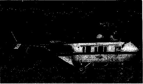
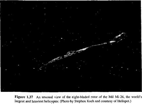
Mikhail Mil adopted the single main rotor and tail rotor helicopter configuration, with the Mi-1 flying in 1950. The Mi-2 was a turbine-powered version. The more efficient Mi-3 (a Mi-1 variant) and larger Mi-4 machines quickly followed. The Mi-4 looked very much like the Sikorsky S-55, but it was actually much bigger and had a greater payload and better performance. The Mi-2 was also built in significant numbers in Poland, with the Mi-4 being produced in China. The Mi-6 of 1957 was one of the largest helicopters ever built, with a rotor diameter of 115 ft (35 m) and a gross weight of over 93,700 lb (42,500 kg). This was followed by the smaller Mi-8 (similar to the Mi-4), which went into civilian service. The Mi-10 of 1961 was a flying crane development of the Mi-6, with a tall, wide, quadricycle landing gear. However, the credit for the world’s largest helicopter goes to the Mi-12, which was designed to carry nuclear missiles. This aircraft had a side-by-side rotor configuration, with the span of the aircraft from rotor tip to rotor tip, exceeding the wing span of the Boeing 747. Power was provided by four turboshaft engines, installed as pairs at the end of each wing pylon. The Mi-24 was designed in 1972 as an evolution of the Huey gunships, and it has been produced in large numbers. The Mi-26 entered service in 1982 and is the largest and heaviest helicopter currently flying (Fig 1.37). It has a rotor diameter of 105 feet

Maturing Technology

(32 m), with a useful payload of up to 44,092 lb (20,000 kg) and a maximum gross weight of 123,459 lb (56,000 kg). The Mi-28 is an attack helicopter, similar in configuration to the AH-64 Apache. The latest Mil design, the Mi-38, is planned as a successor to the Mi-8/17, which is similar in size and weight to the Agusta-Westland EH-101.

The Kamov company has built a series of very successful light – and medium-weight coaxial rotor helicopter designs, including the Ka-15 and Ka-18 in 1956 and the Ka-20 in 1961. Kamov has been the only company to ever put the coaxial helicopter design into mass production, although there have been many proposed and prototype coaxial rotor helicopter designs. Nikolai Kamov had built an autogiro as early as 1929, inspired by the success

A"P Til On rl a 10 r^tbrxro IT огплхг Ki nil onirat*o1 nth ar mnrlalr rvf оп1агм»*лг fKrAiirrK 1 0/1T TVi/a Ui «J It-CtJLl Vi-x-/ J. CI va. JL. VCU. JLIVJ V I_/U.11L L>V^VV^iai J± a. U.l. KJglLKJd tlllVJUgU JL y’-ru. ± IIV

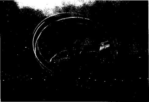
Kamov helicopter company was formed in 1945 and was at first a naval design bureau; the relatively compact coaxial rotor was the only configuration that allowed a helicopter to operate from the small deck of a ship. The Ka-8 and Ka-10 were small lightweight coaxial rotor designs, but they were underpowered. The first real success came with the Ka-15 and Ka-18 in the late 1950s. The Ka-26 used radial engines, but the Ka-126 and later models were all turboshaft powered. The Ka-27 and the civilian model Ka-32 (see Fig 1.38) have been in production since 1972. One of the most recent Kamov designs is the Ka-50, which is a lightweight attack helicopter of considerable performance. One exception to the Kamov coaxial line was the Ka-22 convertiplane of 1961. Another new design is the Kamov Ka-62, which is a conventional light-utility helicopter design incorporating a fenestron that in 2004 was in the prototype stage. See the Kamov Company (2004) for more information.

Another famous Russian designer, Alexander Yakolev, built many successful fixed-wing designs, but with the assistance of Mil designed the large tandem Yak-24 “Flying Boxcar” helicopter in the early 1950s. This helicopter was produced from about 1952 to 1959, but

Maturing Technology

Figure 1.38 A Kamov Ka-32 coaxial rotor helicopter revealing its dual rotor wake structure through natural condensation effects. (Photo courtesy of Dany Gaule and http://www. Airliners. net.)

it was not very successful with persistent vibration problems and relatively few of the type saw actual service. Further information on Russian helicopter developments is given by Anoschenko (1968) and Everett-Heath (1988).

Toward Mass Production

The immediate post-WW2 era is marked by a significant increase in the number of prototype helicopters, many of which went into scale production. It has already been mentioned how the development of the engine was an enabling technology for the helicopter, with rapid advancements in power output and reductions in engine weight taking place during the war. This was accompanied by simultaneous reductions in the empty airframe weight of the helicopter through the use of high-strength, lightweight construction materials such as aluminum and lighter alloys of steel, as well as developments in aerodynamics, flight control effectiveness and improved flight stability. This period represents a concrescence of various technologies and the onset of commercial success for the helicopter. This time period also coincides with the postwar economic recovery, which led to the maturation of helicopter technology and mass production, with increasing use of the helicopter in both military and civilian roles.

Before long, Sikorsky had refined his VS-300 machine and by 1941 he had started production of the R-4 (Fig. 1.26). In 1943 Sikorsky developed the R-6, which, although still only a two-seater helicopter, was larger and had notably better performance than the R-4. The R-6 was produced in substantial numbers and some of them saw action in the Pacific

Toward Mass Production

Figure 1.26 The Sikorsky R-4B (Navy/Coast Guard HNS-1) being flown by famed heli­copter pilot Frank Erickson, circa 1945.

during WW2. In 1946 Westland Helicopters in Britain obtained a license to build variants of the Sikorsky machines, the first being designated as the WS-51A after the S-51, which was a civilian development of the R-5D. This period was the start of a long relationship between the two companies, which continued for decades. Westland already had a history as a successful fixed-wing manufacturer and, as previously mentioned, they had briefly flirted with autogiros in the 1930s, but the company decided to specialize in helicopters in 1946 [see Mondey (1982)]. After significantly reengineering the Sikorsky machine, Westland called the aircraft the Dragonfly. The Widgeon later followed and this was a very modem looking and powerful version of the Dragonfly with a larger passenger cabin. However, it was the Bristol Aircraft Company that was to build the first fully British designed helicopter, with the Bristol-171 Sycamore (Fig. 1.27) taking to first flight in 1947.

Toward Mass Production

Figure 1.27 In 1947, the Bristol 171 Sycamore was Britain’s first certified helicopter. (Westland Helicopters photo.)

Design refinements and material advancements led to lighter weight water-cooled en­gines, with cylinders arranged in two banks in the form of a “V.” These engines saw considerable development up to and through WW2, with power-to-weight ratios of about

0. 75 hp/lb (1.23 kW/kg) in normally aspirated form and up to ratios of unity in supercharged form (see Fig. 1.17, shown previously). Air-cooled radial engines too underwent significant developments during this period. In 1925, the radial engine had a power-to-weight ratio of about 0.5 hp/lb (0.82 kW/kg), but ratios of 0.9 hp/lb (1.48 kW/kg) were more common­place by the mid-1930s. It was engines in this class that were to give the helicopter the performance that led to its first success as a practical and useful flight vehicle, although

nbll ufifliAiit пглКІотс T7or1; Inali/^rvntarc ІопЯаЯ Іл nfi 117a cfonrlorrl oimlonp nnti/pmlontc

51Ш uvh yyiLiiuui jjiuuivuu* і j uwiо iv/iiuL/u iv uuijlzjV отпиши Ull^lUUV ^/vn

turned vertically, which caused problems with oil fouling of the spark plugs. Also, because the engines had to operate at near to maximum rated power for nearly all of a flight, they had a far lower lifespan than was typical when the engine was used in airplanes. Cooling was also a serious concern, especially in hovering flight. WWII did see the development of purpose-built helicopter engines (derated, repositioned accessories, improved cooling and oil sumps, etc.) to overcome these challenges, but development delays prevented them from seeing much service until after the war. Simultaneous reductions in airframe weight that were brought about by advances in lighter materials saw very rapid improvements in overall performance and payload capability of the helicopter by the mid-1940s.

During 1942, the Cierva-Weir Company, prompted by the success of Sikorsky’s XR-4, proposed a relatively large single rotor machine called the W-9, which was unique in its use of jet thrust to counteract rotor torque reaction – see Everett-Heath (1986). The rotor lacked any collective pitch control and rotor thrust was controlled through changing rotor speed as in the pre-WW2 Weir W-5 and W-6 models. The machine demonstrated several

pAt* tllA АГО 1ПЛІ11/І1ПА Г/4гЛИІ1 АОІ 11 Г КаАПІА/^ fluT^f АЛТі^ГЛІР T-T АТТ7АЛ ТОГ*

i^uinivaji ішшуаишю iui uiv ua, uiviuuuig ujuiaunv/anj ukjkjoіл*лд wuuvio. iivwvyvjl, the W-9 crashed during a test flight in 1946 and the project was subsequently abandoned. The Weir and Cierva companies later went on to design the W-11 Air-Horse, which was a unorthodox three-rotor helicopter with considerable lifting capability – see Everett-Heath

(1986) and Leishman (2003). While successful, this machine also crashed during a test flight and further work was terminated. The final helicopter of the Cierva-Weir line was the W-14 Skeeter, which was a small two-seater training helicopter designed in 1948. This machine saw a production run through 1960, and was used by the British and German armed forces.

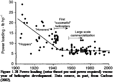
One measure of the lifting efficiency of a helicopter is its power loading, which is defined as the ratio of the weight of the machine to the power required for hovering flight (see Chapter 2). This can be further qualified by defining the power as that delivered to the rotor shaft and not the installed engine power. The higher the power loading, therefore, the more efficient the machine as a vertical lifter and hoverer. Figure 1.28 shows power loading as a function of year of helicopter development. Several points are worthy of note here.

TJirct ttAfina tliot aorlxr kalir*Anfarc Viosl о ralofurobr Vtmti гл«;аг іаоИішт о гаспіі г*лгіЬ*ог7 і 1X01} iivuw uiut wcuxj livuvvj^tvio iiuu u ivmuYVij m^ii pvtvva. rvuuiugf u – xv’uuxt wiiu. ш.у

to initial expectations, yet these machines were not successful other than making brief hops or hovers. This is because they were overweight (high empty weight fraction) and underpowered, and also because the rotors had poor aerodynamic efficiency. The point of initial “success” for the helicopter, which is about 1938-1940, represents the concrescence of engine, materials, and airframe construction technology, along with advances in the aerodynamic performance of the rotor. At this point, the values of power loading to enable basic hovering and forward flight with significant useful payload were first realized. This coincides with a significant increase in the number of prototype helicopters. Second, notice that there is a distinct “knee” in the curve in Fig. 1.28 in the late 1940s and early 1950s. This

Year of first development

Подпись: Figure 1.28 Power loading (rotor thrust per unit power required) versus year of helicopter development. Data source, in part, from Carlson (2002).

coincides with the postwar economic recovery, which led to the maturation of helicopter technology and mass production, with increasing use of the helicopter in both military and civilian roles. Finally, notice from Fig. 1.28 that after this period the values of power loading for later helicopters stay relatively constant at between 5 and 7 lb/hp (1.7 to 2.35 kg/kW), whereas one misht hav*1 tn «рр inrxp. asps in nnwe. r lnadinp as я result of further

О ^^ rw" ‘ О————- ————

technological advances and lightweight engines. While these advances have indeed taken place [e. g., Carlson (2002)], parallel increases in main rotor disk loading to reduce the size and cost of the helicopter have caused power loading values to stay relatively constant.

It is significant to note that while helicopters were becoming more and more successful, the development of the autogiro continued in Europe and the United States well into the 1950s. Considerable development work was undertaken by the Pitcairn [see Pitcairn (1930) and Smith (1985)] and Kellett aircraft companies in the United States. Harold Pitcairn patented many concepts in rotor blade design and rotor control, many of which were li­censed and used by various helicopter manufacturers. The unfortunate timing of autogiro development, however, led to its limited success with the military. The US Navy considered the autogiro for shipborne use in submarine detection and convoy defense. Initial trials of the Pitcairn XOP-1 autogiro, however, were less than impressive, with the Navy citing poor range, insufficient payload capability and limited center of gravity travel. While later mod­els of the autogiro had much improved capabilities, the Navy remained unconvinced. The. US Army later tested both the Kellett and Pitcairn machines in a variety of roles, including reconnaissance and battlefield observation. The low-speed loiter capability of the autogiro seemed particularly promising for artillery spotting roles, and the Army saw the autogiro as a promising start to a new class of aircraft. The Navy would continue to reject any rotating-wing aircraft concept out-of-hand (until ordered by Congress to desist in 1943) and did buy some autogiros built by Kellett. Other rotor design patents from the Weir and Cierva companies in Britain were transferred to the Pitcaim-Larsen Company (as it was later known) and then to the G&A (Gliders & Aircraft) Division of the Firestone Tire & Rubber Company. They subsequently built a small prototype helicopter, first flown in 1946, called the G&A XR-9, which was designed by Harold Pitcairn.

In Britain during the 1940s and 1950s, the autorotating rotor concept was pursued to some significant end by the Fairey Aviation Company. The Fairey Girodyne compound aircraft (or convertiplane) used a propeller set on the end of a stub wing to provide both propulsion and anti-torque – see Everett-Heath (1986). The Fairey Company went on to develop the Jet Girodyne in which the rotor system was driven by tip jets based on the von Doblhoff principle. This ultimately led to the Rotodyne, which was the world’s biggest gyroplane with a cabin big enough for forty passengers – see Hislop (1958) and the more detailed description Section 12.17. The aircraft set a world speed record for a convertiplane in 1959 before the project was canceled. Smaller single – and two-seat autogiros were later developed by various individuals and small companies for the private market.

Besides Igor Sikorsky, there were several other designers in the United States who were pioneering the helicopter during the 1940s. These included Arthur Young, Frank Piasecki, Stanley Hiller, and Charles Kaman. In the late 1930s, Arthur Young began a series of experiments with model helicopters that were ultimately to lead to the design of the renowned Bell Model 47 helicopter. After much research, Young invented the teetering rotor with a stabilizer bar; see Young (1948, 1979). This, bar had bob weights attached to each end and was directly linked to the rotor blades through the pitch control linkages. The idea was that if the rotor was disturbed in pitch or roll, the gyroscopic inertia of the bar could be used to introduce a compensating cyclic pitch into the main rotor system, increasing the effective damping to disturbances and giving stability to the rotor system – see also Kelly (1954).

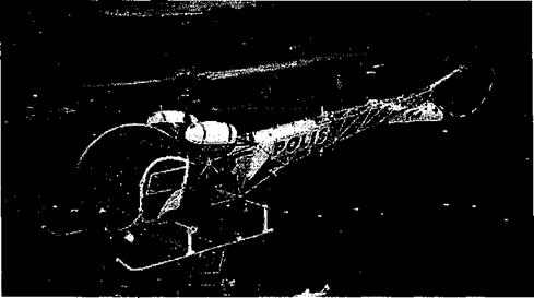
The prototype Bell Model 30 was built in 1942 and had a single main teetering rotor with Young’s stabilizer bar. The first untethered flights took place in 1943 and the machine was soon flying at speeds in excess of 70 mph (112 kph). The Bell Model 30 design led to the famous Bell Model 47 (Fig. 1.29), which was the world’s first commercially certified helicopter. During its nearly thirty-year manufacturing period over 5,000 were produced in the United States alone and many were also license built in more than twenty other countries. Tipton (1989), Brown (1995), and Spenser (1999) give a good historical overview of the

Toward Mass Production

Figure 1.29 A version of the Bell Model 47, which was the world’s first commercially certified helicopter. (By permission of Bell Helicopter Textron.)

Bell machines. Schneider (1995) gives a short biography of Arthur Young and his novel teetering rotor design.

In 1943, Frank Piasecki designed and flew a small helicopter that was called the PV-

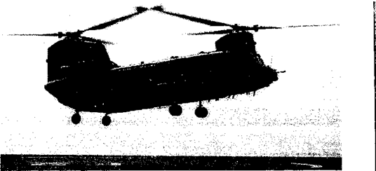
2. Piasecki, who had previously worked for Platt-LePage, developed the fourth heli­copter to fly in free-flight in the United States after the Platt-LePage XR-1 and Sikorsky’s VS-300, and the successful XR-4. Piasecki’s company was to develop the overlapping tan­dem rotor configuration, a concept patented by Gish Jovanovich and demonstrated as early as 1944. Piasecki immediately turned to larger helicopters and in 1945 his company, the P-V Engineering Forum, built a tandem rotor helicopter called the PV-3 Dogship. Details are given by The Piasecki Corporation (1967) and Spenser (1999). This aircraft was popu­larly called the “Flying Banana” because of its distinctive curved fuselage shape. Despite its unfortunate nickname, however, the aircraft was very successful and larger and more powerful versions quickly followed, including the H-16 and H-21 “Workhorse” models of 1952, which were built by the Piasecki Corporation. The Piasecki Corporation became the Vertol Company who developed the Model 107 (CH-46) in 1956 and a larger military tandem rotor model, the CH-47 (Fig. 1.30), was to be the mainstay product for the company. The Vertol Company finally became Boeing Helicopters. An overview of the Boeing-Vertol machines produced up to the mid-1970s is given by Grina (1975). In the late 1980s, the com­pany produced a demonstrator of an advanced technology tandem rotor helicopter called the Model 360. The only other company in the United States to build a tandem helicopter design was Bell, who manufactured the unsuccessful HSL-1 during the 1950s.8 In 1998, Boeing announced the launch of the CH-47F and the CH-47SD “Super-D” Chinook, with the latest model being the MH-47G. See The Boeing Company (2005).

The British company, Bristol Helicopters, had designed and built a single rotor helicopter and later tandem helicopter during the late 1940s under the leadership of the helicopter

Подпись: і
Toward Mass Production

The failure of the HSL-1 was partly responsible for the amazing success of Sikorsky’s S-58.

pioneer Raoul Hafner-see Hobbs (1984) andEverett-Heath (1986). The Type-171 Sycamore (Fig. 1.27) was the first British helicopter to be certified for civil use – see Hafner (1949) and Dowling (1992) for details. The Bristol Type-173 had a long, slim fuselage with two three-bladed rotors at each end, similar to the Piasecki machines. The Bristol Type-192 Belvedere was an improved tandem rotor design, which followed in 1958 with more pow­erful turboshaft engines. However, the Bristol company found it difficult to compete with helicopters being produced by Sikorsky and Westland, and more limited numbers of their helicopters were produced.

In the United. States, Charles Kaman adopted Anton Flettner’s synchropter rotor design. One of Kaman’s innovations was the use of torsionally compliant solid spar spruce rotor blades with servo-flaps. The servo-flaps were mounted at the three-quarter rotor radius, some distance behind the elastic axis of the blade. When these flaps were deflected cyclically, the aerodynamic moments caused the blades to twist, changing their angle of attack and thus in­troducing a cyclic pitch rotor control capability – a system first used by d’ Ascanio (Fig. 1.20). The first Kaman helicopter, the K-125A, flew in 1947. By the 1950s the turboshaft engine had almost entirely replaced the reciprocating engine in most aircraft, including the heli­copter. The Kaman K-225, became the first helicopter to fly powered by a turboshaft engine. A family of larger machines, known as the H-43 Huskie and its derivatives, were produced through 1964. While Kaman reverted to conventional single rotor helicopter designs in the later 1950s, the servo-flap concept continued to be a trademark of all of the Kaman helicopters. The H-2 Seasprite first flew in 1959 and has been produced in considerable numbers. Kaman has recently returned to the synchropter concept with the design of the К-Max (Fig. 1.31), which first flew in 1991. See Kaman Aircraft Corporation (2005) for further details of their helicopter lineage.

Toward Mass Production

Figure 1.31 A modem synchropter design, the Kaman К-Max. (By permission of Kaman Aircraft Corporation.)

Stanley Hiller is another American pioneer in the development of the modem helicopter – see Straubel (1964) and Spenser (1992, 1999). Hiller built several helicopter prototypes,

Подпись: 1*1 mil,

Подпись: Figure 1.32 A Hiller 360, showing the distinctive Rotor-Matic “paddles” to enhance flight stability.

including the coaxial ХЫ-44, which flew successfully in 194ч-. /iuiougn пшеї pmsueu

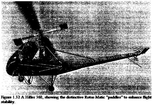
other coaxial and tip-jet driven rotor machines, his later helicopters used a conventional main rotor and tail rotor configuration. His main breakthrough was the development of the “Rotor-Matic” main rotor design, where the cyclic pitch controls were connected to a set of small auxiliary blades set at 90° to the main rotor blades. These auxiliary blades or “paddles” worked in a similar manner to the Bell stabilizer bar, providing compensating cyclic pitch inputs and effecting damping in pitch and roll helping to augment the hovering stability of the machine. The basic theory of both stabilizing concepts are nicely explained by Sissingh (1948). It is significant to note that both Hiller and Young designed stability – producing mechanisms for their helicopters, whereas the Sikorsky machines had none and so they had a reputation for being harder to fly. While the Hiller machines are probably less well known than those of Sikorsky or Bell, the Hiller Company went on to build thousands of helicopters, including the 360 model (Fig. 1.32) and its further evolutions – the UH-12A and H-23.

The First Successes

During the period 1930-1936, the famous French aviation pioneers Louis Breguet and Rene Dorand made notable advances in helicopter development. Figure 1.22 shows their machine of 1935, which was relatively large with coaxial rotors. Boulet (1984) and Kretz (1987) give an excellent account of the work. Each rotor had two tapered blades that were mounted with flap and lag hinges and were controlled in cyclic pitch using a swashplate design. Yaw control was achieved by differential torque on one rotor with respect to the other. Horizontal and vertical tails were used for increased stability. For its time, the aircraft held several flight records, including a duration of 62 minutes and distance flown (27 mi, 44 km). This was arguably the first successful helicopter because, not only did it demonstrate a remarkable new level of performance, but it had a good level of flight safety in that it could autorotate to the ground – see page 6. Clearly, all aircraft must possess safe flight characteristics after a loss of power. While a fixed-wing aircraft can glide, the helicopter can take advantage of autorotation with the rotor unpowered as a means of maintaining rotor rpm, lift, and control in the event of engine failure. In this mode, the helicopter behaves very much like an autogiro so that the relative wind comes upward through the rotor disk. The pilot, in effect, gives up altitude (potential energy) at a controlled rate for kinetic energy to drive the rotor and, with skill, can autorotate the aircraft safely onto the ground.[9] However, with the higher disk loadings found on helicopters compared to autogiros, to get the rotor to autorotate the helicopter must descend at a relatively high rate. While autorotations were

The First Successes

Figure 1.22 The technically successful Breguet-Dorand coaxial helicopter, circa 1936. (Courtesy NASM, Smithsonian Institution, SI Neg. No. A-42078-C.)

attempted with the Breguet-Dorand machine, some moderately successful, the aircraft crashed, and further work stopped prior to the outbreak of WW2.

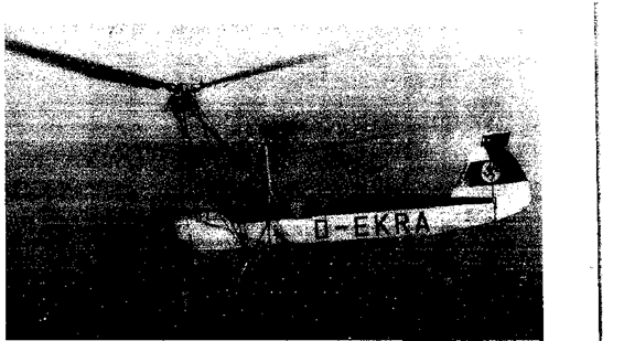
Henrich Focke of the Focke Wulf Company began his work on rotating-wing aircraft as early as 1923. He acquired a license to build Cierva’s autogiros and successfully manufac­tured the C-19 and the C-30 models. From the experience he gained and after many wind tunnel tests, Focke began developing the Fw 61 helicopter as a private venture in 1934. Focke was later to state in a RAeS lecture [see Focke (1965)] that “I was brought to the task of making the first practical helicopter because Cierva did not do it himself.” In 1937, Henrich Focke finally built and demonstrated a successful side-by-side, two-rotor machine, called the Fw 61. The details of the machine are described by Focke (1938, 1947, 1965), Boulet (1984), and Coates (2002). Figure 1.23 shows that the rotors were mounted on outriggers and were inclined slightly inward to provide lateral stability. The blades were tapered in planform and were attached to the rotor hub by both flapping and lagging hinges. Longitu­dinal control was achieved by tilting the rotors forward and aft by means of a swashplate mechanism, whereas yaw control was gained by tilting the rotors differentially. The rotors had no variable collective pitch, instead using a slow and clumsy system of changing rotor speed to change the rotor thrust. A vertical rudder and horizontal tail provided additional directional stability.

Focke’s Fw 61 machine is significant in that besides demonstrating fully controlled flight, it was the first helicopter to repeatedly demonstrate successful autorotations to the ground. Provision was made in the design for a fixed low collective pitch setting to keep the rotor from stalling during the descent. It also set records at the time for duration, climb to altitude (11,427 ft, 3,427 m), forward speed (76 mph, 122 km/h), and distance flown in a straight line (143 miles, 230 km). The machine gained considerable publicity prior to the outbreak of WW2 when the famous test-pilot Hanna Reitsch flew it inside a Berlin sports

arena. While apparently portrayed as a well-mannered helicopter, Reitsch reported that it was not an easy machine to fly and it had some concerning handling defects. The Fw 61 was developed further in collaboration with Gerd Achgelis (which was known in some circles as the Fa 61) and was used as a basis to develop the Fa 266 (Fa 233E), which first flew in 1940. This was a fairly large helicopter, with two three-bladed rotors and could carry up to four crew. It went into limited production during WW2. Boulet (1984) and Coates (2002) give good accounts of the later helicopter work of Focke.

A few examples of the Fa 233 survived WW2 and were taken to Britain, France, and Russia for further evaluation. The French developed the SE 3000 from the Fa 233, which flew in 1948 but it did not go into service. Some the German machines were used as a basis to develop helicopters in Russia, a good account being given by Everett-Heath (1988). The Platt-Le Page XR-1 (see page 32), which was built in the United States after WW2 was based on the Fa 233 design. Yet, despite the apparent success of the side-by- side rotor design, it suffered from a serious lateral instability while hovering in ground effect.

With the assistance of Cierva, the Weir Company had formed an aircraft department in Scotland in 1932. The W-5 was their first true helicopter design, the W-l through W-4

Подпись:Подпись: UWUViJV VSJLThe First Successes
batrinrr oil Кррп QiitAmmo TnirialK; tbp W_^ лі/qo о paoviqI НаоІггп іілхігрх/рг

UUTlll^ Ull UVVli UUW^Xl ) U1V Y Y «_/ YYUO U WUAim UVUlgJU) UV/VTVT vi)

various technical concerns, Weir instead capitalized on the success and apparent flight stability of the German Fw 61 and adopted the side-by-side rotor configuration with the rotors on outriggers. The resulting W-5 incorporated the engine and rotors from the W-4 autogiro and was a rather diminutive machine overall. The two rotors used two untwisted blades with full articulation using flapping and lead-lag hinges, and were given cyclic pitch capability by using a swashplate mechanism. Pitch and yaw control was obtained by tilting the rotor disks, with roll control being obtained by a differential pitch input to the rotors. There was no direct collective pitch, with rotor thrust changes being effected by changes in rotor rpm, a rather slow and unresponsive procedure that was to remain a feature of the

The First Successes

Figure 1.24 The Weir W-6 was Britain’s third helicopter and in 1939 was the first heli­copter to carry a pilot and a passenger.

later Weir-Cierva helicopter designs. The first free hovering flights of the W-5 were made in June of 1938.

The Weir W-6 retained the side-by-side rotor concept of the successful W-5, but used two, three-bladed rotors, each of 26 ft (7.93 m) in diameter. The blades were fully articulated with flapping and lead-lag hinges, with a feathering capability. As shown in Fig. 1.24, a skeletal airframe (of welded steel and light alloy tubing) formed the primary structure. Rotor control was achieved using cyclic and differential collective pitch, with the same method of changing rotor rpm used on the W-5 to effect changes in rotor thrust. The first flights of the W-6 were conducted during October of 1939 and the machine demonstrated good control and performance with speeds in forward flight of over 80 mph and rates of climb in excess of 600 ft/min (3.05 m/s) being attained. See Everett-Heath (1986) and Leishman (2002b, 2004) for further information on the Weir machines.

The imminent outbreak of WW2 ended all research and development on British rotor – craft. The Government’s effective moratorium on British rotorcraft developments in favor of the American Sikorsky designs, albeit only for a few years, was to be a serious blow to the Cierva, Weir, and Hafner companies. It was not to be until 1943, in response to the first official British government design specification for a helicopter, that British rotorcraft development was to start again. By that time, the US had accelerated into the technical lead. With the rapid advances by Igor Sikorsky in 1939 and early 1940s, engineers in the US were to shelve any further technical development of the autogiro and were to focus all new work on helicopters. Much of the future technical work on rotorcraft, both experimental and theoretical, took up where the autogiro had left off. In Britain, this saw the revival of the Cierva Company in 1944 and the development of the Cierva W-9, which was a single rotor helicopter.

During the period 1938-1943, Anton Flettner of Germany developed several helicopter designs. His FI 184 was an autogiro but like the Hafner AR. III it used cyclic pitch control, allowing the pilot to tilt the rotor. This machine was modified to a single rotor shaft driven helicopter (the FI 185), with the addition of collective pitch control and two smaller differ­entially thrusting propellers on outriggers for anti-torque. While the FI 185 flew, Flettner’s big success came with using a side-by-side intermeshing rotor configuration, which became known as a synchropter – see Braun (2003). This intermeshing design was first patented by Bourcart in 1903 and by Mees in 1910. In the synchropter design, the rotor shafts are close

together but arranged so that they are at a significant outward angle with the overlapping rotors turning in opposite directions [see Fig. 1.3(e)]. A gearing system ensured the exact phasing of the rotors. In 1939, Flettner’s FI 265 synchropter was the first helicopter to demonstrate transition into autorotation and then back again into powered flight. Flettner built several other machines, including the FI 282 Hummingbird. The FI 282 was probably one of the first helicopters to be produced in quantity and saw some limited use (but no operational service) during WW2 – see Coates (2002). In the United States, the Kellett Aircraft Company (which also built autogiros as a licensee to Pitcairn) also developed a synchropter configuration and built the XR-8 in 1944 using three-bladed intermeshing rotors. The aircraft flew successfully, but it never went into production. The synchropter concept was also adopted by Charles Kaman, but this time the Kaman Aircraft Corp. was to put the type into quantity production for the US military.

In the early 1940s Friedrich von Doblhoff of Germany began investigating the application of the tip-jet principle to a helicopter and by 1942 had built the first helicopter to take off using tip jets. A conventional piston engine drove a compressor, and the compressed air was mixed with fuel before passing through hollow rotor blades to combustion chambers situated at the blade tips. Because of their high specific fuel consumption, tip jets can be used economically only for takeoff, hovering and landing. For forward flight, the tip jets were shut off and the rotor operated in autorotation like an autogiro. After WW2, von Doblhoff was involved in the development of the McDonnell XV-1 compound helicopter – see Section 12.17.

The Americans too were working on helicopter designs. As described earlier, Igor Sikorsky had experimented in Czarist Russia with primitive vertical lift aircraft as early as 1907 – see Sikorsky (1938) and Finne (1987). After Sikorsky had emigrated to the United States, he went on to design and build flying boats. A 1935 Sikorsky patent (No. 1,994,488) shows a relatively modem-looking single rotor/tail rotor helicopter design with flapping hinges and a form of cyclic pitch control. Although Sikorsky encountered many technical challenges, he tackled them systematically and carefully. To some the machine was known as “Igor’s folly,” an unjustified designation by those who did not believe in the future of rotating-wing aircraft, but it also reflected the relative mechanical complexity and difficult flying characteristics of the early helicopter prototypes. Sikorsky’s first helicopter, the VS – 300, was flying in free, untethered flight by May 1940. A good summary of the technical design is given by Sikorsky (1941, 1942,1943).

Sikorsky’s first machine (Fig. 1.25) had one main rotor and three auxiliary tail rotors, with longitudinal and lateral control being obtained by means of pitch variations on the two vertically thrusting horizontal tail rotors. The machine could hover, fly sidewards and backwards, yet it could not fly forward very well, exhibiting a sudden nose-up pitching characteristic at a low forward airspeeds. This was because of the downwash of the main rotor wake, which as airspeed built, blew back onto the two vertically thrusting tail rotors and destroyed their lift. The main lifting rotor of the VS-300 was used in the later VS-300A, but now only the vertical (sideward thrusting) tail rotor was retained out of the original three auxiliary rotors. In this configuration, longitudinal and lateral control was achieved by tilting the main rotor by means of cyclic pitch inputs; the single tail rotor was used for anti-torque and directional (yaw) control purposes. This configuration was to become the standard for most later helicopters.

In June of 1941, the Platt-LePage XR-1 helicopter was to make its first free flights. Developed by two American engineers, W. Laurence LePage and Havilland H. Platt, the XR-1 was funded by a government contract under the Dorsey-Logan Act (see page 713). W. Laurence LePage had previously worked the Pitcairn and Kellett companies. The XR-1 followed the lead of the Focke Fw 61 by using a side-by-side rotor configuration. The

The First Successes

Figure 1.25 Sikorsky’s VS-300 helicopter flew in 1940 and pioneered the single rotor con­figuration, but it followed several European helicopter designs. (Photo courtesy of Sikorsky Aircraft.)

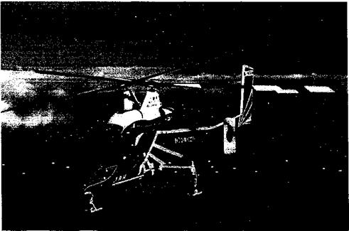
XR-1 was found to be difficult to fly, with high vibrations and control problems. Several years of development followed, although its capabilities were soon eclipsed by the Sikorsky machines and the XR-1 was never to go into production. After WWII, McDonnell continued to develop the side-by-side rotor concept under contract to the US Navy. The McDonnell XHJD-1 Whirlaway was a similar but larger and heavier helicopter than the XR-1, using a separate engine to drive each rotor. Like the XR-1, the XHJD-1 was to suffer from a host of technical problems and McDonnell quickly fell behind the Sikorsky and Piasecki Companies in helicopter development. While the side-by-side rotor configuration proved to be a bad design choice for helicopters, it is perhaps significant to note that the configuration was later adopted for use in tilt-rotors – see Section 1.13.

On the Verge of Success

In 1922, under contract to the US Army, a Russian emigre to the United States by the name of Georges de Bothezat built one of the largest helicopters of the time. De Bothezat had been a student of Professor Joukowski) in Russia (see previously) and had written one of the first technical manuscripts on rotating-wing aerodynamics – see de Bothezat (1919). De Bothezat’s machine was a quadrotor with a rotor located at each end of a truss structure of intersecting beams, placed in the shape of a cross (see Fig. 1.18). Ivan Jerome was the codesigner. Each rotor had six wide chord blades. Control of the machine was achieved by collective, differential collective, and cyclic blade pitch variations. The blade control design likely derived directly from those of Yuriev. A set of four smaller rotors served to help control the machine. In 1922, the ungainly Jerome-de Bothezat quadrotor or “Flying Octopus” flew many times, albeit at low altitudes and slow forward speeds. It was not very controllable and its “forward motion” was really a result of wind drift. Because of insufficient performance and the increasing military interest in autogiros at the time, the

On the Verge of Success

Figure 1.18 The Jerome-de Bothezat helicopter, which made limited controlled flights in 1922. (Courtesy NASM, Smithsonian Institution, SI Neg. No. 87-6022.)

project was soon to be canceled. But it was to be twenty or more years before a helicopter was again to fly again in the United States and better de Bothezat’s accomplishments.

In 1921, Etienne (Ehmichen of France built a quadrotor machine in a similar style to that of de Bothezat, but with eight additional smaller rotors for control and propulsion. (Ehmichen conducted many rotor experiments, including tests made in a wind tunnel of his own design. His quadrotor machine (Fig. 1.19), however, typified the cumbrous mechanical complexity of several other helicopters of this era. His initial design was underpowered and it was fitted with a hydrogen balloon to provide additional lift and stability during the initial period of development. (Ehmichen’s No. 2 machine was flown between 1923 and 1924. By 1924, (Ehmichen was making reasonable flights and his machine proved

On the Verge of Success

Figure 1.19 The (Ehmichen quadrotor machine typified the mechanical complexity and impracticality of most early helicopters.

On the Verge of Success

Figure 1.20 Corradino d’Ascanio’s coaxial machine, circa 1930, which used servo-tabs to twist the blades and cyclically change their lift. (Courtesy of John Schnieder.)

“perfectly maneuverable and stable.” In May 1924 he was awarded a prize by the FAI for demonstrating the first helicopter to fly a standard closed 1 km circuit with a 410 lb (200 kg) payload, which took 7 minutes 40 seconds. The machine, however, was largely impractical. CEhmichen was to build other forms of rotorcraft, including a helicostat, which was developed and flown through 1935. See also NACA (1921) and CEhmichen (1923).

In 1930, Corradino d’Ascanio of Italy built a coaxial helicopter. Figure 1.20 shows that this relatively large machine had two, two-bladed, contrarotating rotors. Following the work of Cierva, the blades had mechanical hinges that allowed for flapping but a feathering capability was added to change blade pitch. Control was achieved by auxiliary wings or servo-tabs on the trailing edges of the blades, a concept that was later adopted by others, including Bleecker and Kaman in the United States. D’Ascanio designed these servo-tabs so that they could be deflected periodically by a system of cables and pulleys, thereby cyclically twisting the blades and changing their lift. For vertical flight, the tabs on all the blades moved collectively to increase the rotor thrust. Three small propellers mounted to the airframe were used for additional pitch, roll and yaw control. This machine held modest speed and altitude records for the time, including altitude (57 ft, 17.4 m), duration (8 minutes 45 seconds) and distance flown (3,589 ft, 1,078 m). D’Ascanio later developed a single rotor helicopter in Italy during WW2, but it was destroyed during a bombing raid.

In 1930, Maitland Bleecker of the United States followed Brennan’s approach to the torque reaction problem by delivering power to propellers that were mounted on each rotor blade. The machine was made by the Curtiss Company. Power was supplied through a system of chains and gears from an engine mounted at the center of the machine. Like d’Ascanio’s machine, Bleecker’s helicopter was controlled by auxiliary aerodynamic surfaces he called “stabovators,” which were fastened to the trailing edges of each blade (see Fig. 1.21). Both collective and cyclic blade pitch were incorporated into the design. Bleecker’s machine accomplished numerous short hops and hovers, but high vibrations and various control problems caused the project to be abandoned in 1933. Liberatore (1998) gives one of the best accounts of the project.

On the Verge of Success

Figure 1.21 The Curtiss-Bleecker helicopter photographed at NACA Langley Research Center in 1930. (NASA photo.)

During 1929-1930, the Russian bom engineer Nicolas Florine built a tandem rotor helicopter in Belgium. The rotors turned in the same direction but were tilted in opposite directions to cancel torque reaction. This idea was later used on the Cierva-Weir W-11 tri­rotor helicopter. Boulet (1984) describes the mechanical aspects of the machine. Florine’s first aircraft was destroyed in 1930, but he had a second design flying successfully by 1933, which made a flight of over 9 minutes to an altitude of 15 ft (4.57 m), exceeding d’Ascanio’s flight duration record of the time. Yet, Florine’s designs suffered many setbacks and work was discontinued in the mid-1930s.

Engines: A Key Enabling Technology

The development of the engine (powerplant) is fundamental to any form of flight. While airplanes could fly with engines of relatively lower power, the success of the he­licopter had to wait until aircraft engine technology could be refined to the point that much more powerful and lightweight engines could be built. A look at the historical record
(Fig. 1.17) shows that the need for engines of sufficient power-to-weight ratio was really a key enabling technology for the success of the helicopter.

Подпись:

Подпись: Figure 1.17 Even after airplanes were flying, engines were to need another twenty years of development before helicopters were to be successful. The advent of the turboshaft engine led to dramatic increases in overall power-to-weight ratio such that it was finally to give the helicopter the performance and payload that made it a commercial success.

‘ I V fVia anfltг ІІлa і*отііі*лг1 ТґЛТ’ оПЛі »-v v ■ і ■ ■

xu tills taujf tilt/ puwvi ivvjuiitu ivi ouvwoutui quantity and an understanding of the problem proceeded mostly on a trial and error basis. The early rotor systems had extremely poor aerodynamic performance, with efficiencies (figures of merit) of no more than 50%. This is reflected in the engines used in some of the helicopter concepts designed in the early 1900s, which were significantly overpowered and very overweight. Prior to 1870, the steam engine was the only powerplant available for use in most mechanical devices. The steam engine is an external combustion engine and, relatively speaking, it is quite a primitive form of powerplant. It requires a separate boiler, combustor, recirculating pump, condenser, power producing piston and cylinder, as well as fuel and an ample supply of water. All of these components would make it very difficult to raise the power-to-weight ratio of a steam engine to a level suitable for aeronautical use. Nonetheless, until the internal combustion engine was developed, the performance of steam engines was to be steadily improved upon, being brought to a high level of practicality by the innovations of James Watt.

The state of the art of aeronautical steam engine technology in the mid-nineteenth cen­tury is reflected in the works of British engineers Stringfellow and Hensen and also the American, Charles Manly. The Hensen steam engine weighed about 16 lb (7.26 kg) and produced about 1 hp (0.746 kW), giving a power-to-weight ratio of about 0.06, which as about three times that of a traditional steam plant of the era. Fueled by methyl alcohol, this was also a more practical fuel for use in aeronautical applications. However, to save weight the engine lacked a condenser and so ran on a fixed supply of water. With a representative steam consumption of 30 lb/hp/hr (18.25 kg/kW/hr) this was too high for aircraft use. A steam engine of this type was also used by Enrico Forlanini of Italy in about 1878 for his experiments with coaxial helicopter rotor models.

In the United States, Charles Manly built a relatively sophisticated five cylinder steam engine for use on Langley’s Aerodrome. The cylinders were arranged radially around the crankcase, a form of construction that was later to become a basis for the popular air-cooled radial reciprocating internal combustion aircraft engine. Manly’s engine produced about 52 hp (36.76 kW) and weighed about 151 lb (68.5 kg), giving a power-to-weight ratio of

0. 34 hp/lb (0.56 kW/kg). The Australian, Lawrence Hargreve, worked on many different engine concepts, including those powered by steam and gasoline. Hargreve, along with the Berliners, was one of the first to devise the concept of a rotary engine, where the cylinders rotated about a fixed crankshaft, another popular design that was later to be used on many different types of aircraft, including helicopters.

The internal combustion engine came about toward the end of the nineteenth century and was a result of the scientific contributions from many individuals. Realizing the limitations of the steam engine, there was gradual accumulation of knowledge in thermodynamics, mechanics, materials, and liquid fuels science. One of the earliest studies of the thermody­namic principles was by Sadi Carnot in 1824 in his famous paper “Reflections on the Motive Power of Heat.” In 1862, Alphose Beau de Rochas published the first theory describing the four-stroke combustion cycle. In 1876, Nikolaus Otto was to use Rochas’s theory to design an engine that was to form the basis for the modem gasoline-powered reciprocating engine. The development of the internal combustion engine eliminated many parts, simplified the overall powerplant system and for the first time enabled the construction of a compact powerplant of relatively high power-to-weight ratio suitable for an aircraft.

The earliest successful gasoline-powered aircraft engines were of the air-cooled rotary type. The popular French “Gnome” and “Le Rhone” rotary engines had power-to-weight ratios of 0.35 hp/lb (0.58 kW/kg) and were probably the most advanced lightweight engines of their time.[8] This type of engine was used by many helicopter pioneers of the era, including Igor Sikorsky in his test rig of 1910. The rotary engine suffered from inherent disadvantages, but compared to other types of engines that were available at the time, they were smooth running and sufficiently lightweight to be suitable for aircraft use. One major technology to enable vertical flight, the powerplant, was now finally at hand.

Not Quite a Helicopter

The Spanish engineer Juan de la Cierva had built and flown another type of rotating – wing aircraft as early as 1923 – see Juan de la Cierva (1926, 1930). This aircraft looked like a hybrid between a fixed-wing airplane and a helicopter, with a set of conventional wings and a tail, but with a rotor mounted on a vertical shaft above the fuselage. However, unlike a helicopter, this rotor was not powered directly and was completely free to turn on its shaft. Cierva found that when the rotor disk was inclined backward at a small angle of attack and as the machine was pulled forward by a propeller, the rotor was turned by the action of the airflow on the blades. This aerodynamic self-rotation of the rotor is called “autorotation,” and had been understood by Crocco and Yuriev before 1910. Yet the idea of pulling the rotor horizontally through the air to generate lift was clearly that of Cierva. He called his rotating-wing aircraft an “Autogiro.” The name “Autogiro” (with an “A” and an “i”) was later to be coined by Cierva as a proprietary trademarked name for his machines, but when spelled starting with a small “a” and using a “y” it is normally used as a generic name for this class of aircraft. Today, “gyroplane” is the official term used to describe such an aircraft, although the names “autogiro,” “autogyro,” and “gyroplane” are often used synonymously.

Cierva’s first Autogiro was a coaxial design, the airframe being from a converted WW1 fixed-wing aircraft. The problem of asymmetric lift was well known to Cierva and his first idea of using a contrarotating coaxial design was that the lower rotor would counteract the asymmetry of lift produced on the upper rotor, thereby balancing the net rolling moment on the autogiro. It is the subject of Spanish patent No. 74,322 “Nuevo Aparato de Aviacion” of June 1920. However, the aerodynamic interference produced between the rotors resulted in different rotor speeds, spoiling the required aerodynamic roil balance ana the aircraft crashed. Undeterred, Cierva conducted basic wind tunnel experiments on model rotors, and he was one of the first to establish a scientific understanding of their aerodynamic behav­ior, especially in autorotation. He built two more full-scale machines with single rotors before he achieved final success in January 1923 with the C-4. Based on his tests with small models, this fourth machine incorporated blades with mechanical “flapping” hinges at the root, which Cierva used as a means of equalizing the lift on the two sides of the rotor in forward flight – see Cierva & Rose (1931). This novel solution allowed the blades to flap up or down about these hinges, responding to the changing airloads during each revolution of the blades and providing a means of equalizing the lift between the advancing and retreating sides of the rotor disk. The development of the flapping hinge was to be one key to the future success of the helicopter.

The principle of flapping blades had actually first been suggested for the application to propellers [see Rosen (1984)] apparently by Charles Renard, but the idea of hinged blades was formally patented by Louis Breguet in 1908 and then by Max Bartha & Josef Madzer in 1913 – see Liberatore (1998) for details. Juan de la Cierva, however, must be credited with the first successful practical application of the flapping hinge to a rotor. Cierva noticed that the incorporation of the flapping hinge eliminated any adverse gyroscopic effects and also allowed the lift forces on the two sides of the rotor to become more equalized in forward flight. Metal ties with tumbuckles located near the mid-span linked each of the blades together in an attempt to reduce the in-plane or lead-lag motion of the blades (see Chapters 4 and 12 for details). Cierva’s initial avoidance of using a lead-lag hinge to alleviate the in­plane blade drag and Coriolis forces (resulting from the flapping motion) was an oversight that was rectified on later models of his Autogiro.

In all of Cierva’s Autogiros, the engine drove only the propeller. Clearly this makes the autogiro mechanically simpler than a shaft driven helicopter because the engine gearbox and rotor transmission can be dispensed with. Furthermore, it is not necessary to develop a separate means of countering torque reaction, as on the helicopter. This all significantly reduces weight and also reduces design, production, and capital costs. Starting the rotor, however, required a team of helpers to pull a rope wound around the rotor shaft, or taxiing around on the ground could also get the rotor spinning. Later models used a mechanical prerotator – see Section 12.6. Thereafter, the pilot opened the throttle and the thrusting propeller pulled the machine forward until it quickly lifted off into flight. The freely spinning rotor turned relatively slowly in flight compared to a helicopter, about 100-150 rpm.

With the success of his Autogiros, in 1925 Cierva was invited to Britain by the Weir Company. His C-6 Autogiro was demonstrated at the Royal Aircraft Establishment (RAE) and these flights stimulated early theoretical work on rotating-wing aerodynamics by H. Glauert and C. Lock in Britain, and M. Munk in the United States. Cierva was to write two books for the fledgling rotorcraft industry, albeit formally unpublished – see page 701. In later models of his Autogiro, the first of which was the C-8 (Fig. 1.16), Cierva added a lag hinge to each of the blades, which alleviated stresses caused by in-plane drag and Coriolis forces and completed the development of the articulated rotor hub. In later models, a control stick was connected to the rotor hub, which allowed the rotor disk to be tilted for control purposes (orientable direct rotor control). While this allowed the ailerons to be dispensed with, the rudder and elevator on the machine were retained. The Cierva Autogiro Company and its licensees went on to build many more versions of the Autogiro through 1938.

Although the autogiro was still not a direct-lift machine and could not hover, it required only minimal forward airspeed to maintain flight. Cierva proved that his autogiros were very safe and because of their low-speed handling capability, they could be landed in confined areas. Takeoffs required a short runway, but this problem was solved with the advent of the “jump” and “towering” takeoff techniques, although this required a lot of piloting skill – see Section 12.14. For a jump takeoff the blades are set to flat pitch and the rotor rpm is increased above the normal flight rpm using the engine. This is followed by the rapid application of collective blade pitch, while simultaneously declutching the rotor and thereby avoiding any torque reaction on the fuselage. This technique lifts the aircraft rapidly off the ground, powered only by the stored kinetic energy in the rotor system. As forward speed builds, the rotor settles into its normal autorotative state – see Prewitt (1938) for a technical description. To achieve jump takeoffs, in 1935 Cierva introduced a pitch change mechanism into the rotor desigp, which was installed in later production versions of the

Not Quite a Helicopter

Figure 1.16 A version of Cierva’s C-8 Autogiro, circa 1928. The Autogiro was the first successful rotating-wing aircraft and the first type of aircraft to fly successfully after the conventional airplane.

C-30. These machines saw some service with the British Royal Air Force during WW2 for radar calibration missions.

About the same time, Raul Hafner introduced the “spider” cyclic pitch control system to his design of autogiro – see Fay (1987) and Hobbs (1984). This provided a means of increasing collective pitch and also tilting the rotor disk without tilting the rotor shaft with a control stick as in Cierva’s direct control system, giving the pilot better control with lower control forces. Hafner used this design in his AR. III autogiro, which flew in 1935. About the same time, another autogiro using lateral cyclic control was built by W. R. Kay in Scotland. With its nearly vertical towering takeoff capability, low handling speeds and short landing run, this form of the autogiro was to closely rival the soon to be successful helicopter in terms of its performance capability.

Several other British companies, including Weir, A. V. Roe (Avro), Pamall, de Havilland and Westland went on to build variants of the Cierva Autogiro designs. The first Weir designs were developments of Cierva’s models and used the orientable direct rotor control system. The Weir W-l through W-4 models were all autogiros and were some of the first machines to use a prerotator to help bring up the rotor rpm prior to takeoff (see Section 12.6). The de Havilland and Westland company built a few larger prototype autogiros. The Westland C-29 was a five-seat cabin autogiro built in 1934. The aircraft was never flown because it exhibited serious ground resonance problems and the project was canceled with the untimely death of Juan de la Cierva in 1936. However, Cierva’s work was carried on by designers from Weir and another Westland designed autogiro called the CL-20 was flown just before WW2 although it did not show sufficient performance – see Mondey (1982).

The Kellett and Pitcairn companies entered into licensing agreements with Cierva, re­sulting in the first flight of an autogiro in the United States in 1928. Harold Pitcairn went on

to design and patent many improvements into the Cierva rotor system [see Smith (1985)], but it became clear that it was a true helicopter with power delivered to the rotor shaft that was required. The autogiro was extensively tested in the United States by the NACA. Gustafson (1971) gives an authoritative account of the early NACA technical work on autogiros and helicopters.[7] In Russia, the TsAGI built autogiros derived from the Cierva designs. Kuznetsov and Mil built the 2-EA, which was derived from the Cierva C-19 – see Everett-Heath (1986). Later developments of this design led to the first Russian helicopters built with the assistance of Vittorio Isacco, who had earlier led basic helicopter develop­ments in Italy, Spain, and France during the 1920s. The Japanese even made copies of the Cierva and Kellett autogiro designs, combining some of their best attributes and used them as submarine spotters during WW2 – see Gablehouse (1967).

During WW2 the Focke Achelis company built the Fa 330 Kite. This aircraft was a pure autogiro with a relatively simple lightweight construction and was designed as observation platform for one man while being towed behind a surfaced submarine. It was attached to the submarine by a steel cable wound out from a winch on the deck. When returning to the submarine, the winch wound in the cable and pulled the Fa 330 onto the deck. The Hafner Rotachute [see Everett-Heath (1986)] was a skeletal autogiro designed to replace a conventional parachute, but it never saw operational use. The simplicity of both these platforms later formed the inspiration for inexpensive amateur homebuilt autogiros, many of which are still popular today.

While the autogiro did see some commercial success, mainly in the United States, it was never on a large scale. During the 1930s and 1940s it was used by the US Post Office for regular mail service between Washington DC and Philadelphia, as well as in other cities, including Chicago and New Orleans. The 1920s and 1930s were an exciting and adventurous time for aviation despite the Great Depression and the autogiro was widely popularized as a super-safe, easy-to-fly aircraft, which it was for the most part. The autogiro subsequently found its way into the private market, where it gained good popularity with pilots and some level of public acceptance for a somewhat unusual aircraft. It was also used for aerial photography and advertising, the latter role giving it good public exposure. The Buhl Aircraft Corporation of Detroit, Michigan, was another company involved in autogiros. They designed and built a small two-seater autogiro with a pusher propeller, the first of its kind, which had no fixed aerodynamic surfaces other than a tail.

Despite the ultimate demise of the autogiro in the post-WW2 era, it got the public, government and the aircraft industry used to seeing a practical rotorcraft. When serious helicopter proposals started to appear in the early 1940s, they were not rejected out of hand but instead received more respect and consideration than most nascent aircraft technologies receive at that early stage of development. See also Chapter 12 for further details on the technical development of autogiros and modem gyroplanes.

. The First Hoverers

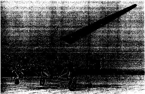
During 1919-1926 Louis Brennan worked on a helicopter concept with a large single two-bladed rotor of 60 ft (18.3 m) in diameter. Graham (1973), Everett-Heath (1986), and Fay (1987) give good accounts of Brennan’s work. Brennan, an affluent scientist who had previously invented the modem torpedo and a monorail system, had a different approach to solving the problem of torque reaction by powering the rotor with propellers mounted on the blades (Fig. 1.13). These were driven by drive shafts running along the blades to gearboxes. Control was achieved by the use of “ailerons” inboard of the propellers, which were actuated by means of compressed air. The machine was powered by a 230-hp Bentley rotary. While Brennan’s work was initially carried out with considerable secrecy, in 1921 the machine was officially being tested at the Royal Aircraft Establishment at Farnborough. In 1922, the machine flew successfully inside a hangar, apparently at one point carrying four “passengers.” Further flights outdoors were undertaken through 1926, where the machine made flights at low altitude and was able to fly about 600 ft (182 m) forward. Lack of stability and control caused the machine to crash on its seventh flight, even with the addition of stability enhancing devices. By 1928 the Air Ministry ordered a concept called a “Helicogyre” designed by the Italian Vittorio Isacco to be built in Britain. The machine made only a few tethered flights. British interest in helicopters quickly faded because of concurrent interest in the autogiro (see Section 1.7).

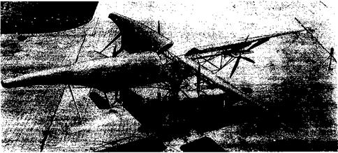
During the early 1920s, Raul Pescara, an Argentinean living and working in Spain and France, was building and attempting to fly a coaxial helicopter with biplane-type rotor blades (Fig. 1.14). On his first machine, each rotor had six sets of blades that were mounted rigidly to the rotor shaft and this was later decreased to four sets per rotor. As described by Boulet (1984), Pescara’s work focused on the need for proper control of the machine, which

. The First Hoverers

was achieved through cyclic pitch changes that could be obtained by warping (twisting) the blades periodically as they rotated. This was one of the first successful applications of a cyclic pitch concept to a helicopter. Yaw was controlled by differential collective pitch between the two rotors. Early versions of Pescara’s machine were underpowered, which

. The First Hoverers

Figure 1.15 Between 1924 and 1930, A. G. von Baumhaeur made attempts to fly a single main rotor helicopter with a separately powered tail rotor. (Courtesy NASM, Smithsonian Institution, SI Neg. No. 77-721.)

may not be surprising considering the large number of blades and high profile drag of the bracing wires of his rotor, and the aircraft did not fly. With a later version of his helicopter using a more powerful engine, some successful flights were accomplished. This attempt reflects much early thinking on helicopters, where more powerful (and heavier) engines were often used rather than trying to make the rotors more efficient. However, as might be expected, these flights were not very successful and with the limited control available they resulted in damage or serious crashes followed by long periods of rebuilding. By 1925 Pescara had finally abandoned his helicopter projects.

Between 1924 and 1930, a Dutchman named A. G. von Baumhaeur designed and built one of the first single rotor helicopters with a tail rotor to counteract torque reaction. Boulet (1984) gives a good description of the machine. Figure 1.15 shows that the fuselage of the von Baumhaeur machine consisted essentially of a tubular truss, with an engine mounted on one end. The other end carried a smaller engine, which turned a conventional propeller to provide a side force and so countering the main rotor torque reaction. The main rotor had two blades, which were restrained by cables so that the blades flapped about a hinge like a seesaw or teeter board. Control was achieved by a swashplate mechanism, which was another early application of this device that was later to provide one standard means of providing blade feathering for collective and cyclic pitch control on the modem helicopter.[6] Unfortunately, von Baumhaeur did not interconnect the main and tail rotors with a transmission, so this caused considerable difficulties in balancing torque and giving proper directional control. Nevertheless, the machine was reported to have made numerous short, hovering flights. It was, however, considerably less capable than the Pescara machine.

In the late 1920s, the Austrians Raoul Hafner and Bruno Nagler designed and built a single-seat helicopter – see Everett-Heath (1986) and Fay (1987). The two variants, the R. I and R. II, used a single rotor configuration with a pair of fixed wings located in the rotor downwash to provide anti-torque. The flights were mostly unsuccessful despite some brief tethered hovering flights of up to a minute. For rotor control, Hafner’s machine in notable in that it used a continuously variable blade pitch change mechanism using a large diameter bearing or swashplate – see Nagler & Hafner (1932). In 1932 Hafner emigrated to Britain, where he and Juan de la Cierva independently continued work on blade articulation for autogiros and later for helicopters. A later variant of the Hafner R. II used flapping blades, which gave’the machine improved control capability. In 1938 Nagler joined Franz Rolz in Germany to form the Nagler Rolz Flugzeugbau, who continued to develop small lightweight helicopter concepts. Hafner was to stay in Britain and became a prolific and forward-thinking rotorcraft designer for Bristol Helicopters [see Hafner (1954)] and later at Westland Helicopters.

The Hoppers

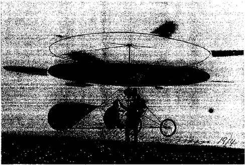
Tn 1 QfY7 dhrviit fmir t/Aare aftpr fliA X/n rrbf РгліКрґє’ firet eiiAPPecfnl плп/агаН fli rrVitc

J. U X S J / 9 UOVVH JLVtU J VU1 О UltVJ. 111V П 1 iglll JJ JL J lllC/1 О 111. Ol OUWVOOl U1 JJV vr V1VU lll^llto

in fixed-wing airplanes at Kitty Hawk in the United States, Paul Cornu of France constructed a helicopter that is reported to have carried a human off the ground for the first time. Boulet (1984) gives a good account of the work. Although Cornu had conducted experiments with small rotor models, he lacked the necessary theoretical understanding of rotor aerodynamics and performance to enable these results to be properly scaled to a full-size helicopter. Such theoretical analyses were not to be widely understood and used until the 1920s. Cornu’s machine (Fig. 1.7) used a skeletal airframe of very simple construction and relatively light weight, being constructed of a 20 ft (6.1 m) length of steel beam bent into a wide U-shape, with six “star” frames all tied together with cables. A rotor was mounted at each end of the main structural beam. The rotors rotated in opposite directions, a necessary requirement to cancel torque reaction. The inner hub part of each rotor looked like large bicycle wheels. At the periphery of each rotor, there were two light, wide-chord and fabric-covered blades. Power was supplied to the rotors by a 24 hp (17.9 kW) Antoinette gasoline motor through a driving belt and pulley transmission, a mechanism that it seems caused Cornu many

пглЫргпс onH тплЬ fmctrofmn толіітл cof лп – Рглпг Кютгліа urVtApIo Л пмтіНігл

иичд 111UVU АХ UJ LA UtiV/ll. 1 UV VV UU1V lliaVllillt’ oai V/ll 1VU1 VYllC’t/lO. n pilllliLl w

means of control was achieved by placing a “plane” or a wing in the slipstream below each of the rotors; the inclination and force on the these wings was controlled by the pilot with two hand operated levers. On November 13, 1907, at Normandy in France, Cornu’s “flying bicycle” was reported to have made several tethered flights of a few minutes at low altitude. In Cornu’s own words, “… the aircraft left the ground with four wheels all together….”

The Hoppers

Figure 1.7 The Cornu helicopter, circa 1907. (Courtesy NASM, Smithsonian Institution, SI Neg. No. 74-8533). ■

The Hoppers

Figure 1.8 The Breguet Gyroplane No. 1, looking somewhat like an assemblage of ladders, made some uncontrolled hops off the ground in 1907.

However, no supporting photographs or eyewitness accounts of his flights have ever been produced. See Boulet (1984) and Leishman (2001a) for further details.

In 1904, the French scientist Charles Richet built a small unpiloted helicopter. Even then, Richet was well-known for work in aerodynamics and had given many lectures on the subject at the French Academie des Sciences. One of Richet’s students, Louis Breguet, was soon to become a famous aviation pioneer. During the latter part of 1906, the Breguet Brothers had begun to conduct helicopter experiments under the guidance of Richet. In 1907 the Breguet Brothers made experiments with a rotary-winged test rig with a force-balance [see Breguet (1936)] and shortly thereafter they built their first helicopter. Their ungainly quadrotor Gyroplane No. 1 consisted of four long girders made of steel tubes and arranged in the form of a horizontal cross (Fig. 1.8). A rotor consisting of four biplane blades was placed at each of the four comers of the cross, giving a total of 32 separate lifting surfaces. The pilot sat in the center of the cross next to the 40 hp (29.8 kW) engine. The machine is reported to have carried a pilot off of the ground into free flight, albeit briefly. These claims may have been exaggerated because photographs show the assistance of several men stabilizing and lifting the machine. Clearly, the machine could never have flown completely freely because, like the Comu machine, it lacked flight stability and a proper means of control. However, the Breguet machine was probably closer to achieving vertical flight than the one made by Paul Cornu – see Boulet (1984) and Leishman (2001b).

Aldridge (1954) describes a helicopter that was built by the designer Edwin Mumford at the William Denny & Brothers’ shipyard in Scotland during 1905. This helicopter consisted of six two-bladed rotors, which were mounted on each side of a skeletal frame. The rotors looked much like ship propellers and could not have been efficient for use in air. Control was provided for by tilting the rotor shafts, with a rudder at the tail for directional control. It is claimed that tethered and free flights of the helicopter were made during 1909, where the craft apparently reached altitudes of 10 ft (3.05 m) and forward speeds of 20 mph (32.2 km/h). Tests apparently continued through to 1914, when the machine was destroyed in a storm. Further work on the project was abandoned because of the start of WW1. See Rees (1990) for further details.

In the early 1900s, Igor Sikorsky and Boris Yuriev independently began to design and build vertical-lift machines in Czarist Russia. By 1909, inspired by the work of Comu,

Breguet, and other French aviators, Sikorsky had built an unpiloted coaxial helicopter prototype. This machine did not fly because of vibration problems and the lack of a powerful enough engine. Sikorsky (1938) stated that he had to await “better engines, lighter materials, and experienced mechanics.” His first design was unable to lift its own weight and the second in 1910, even with a more powerful engine, only made short (nonpiloted) hops. Discouraged, Sikorsky abandoned the helicopter idea and devoted his skills to fixed-wing (conventional airplane) designs at which he was very successful. Although Sikorsky never gave up his vision of the helicopter, it was not until the 1930s after he had emigrated to the United States that he pursued his ideas again (see later). Good accounts of the life and work of Igor Sikorsky are documented by Bartlett (1947), Delear (1969), Sikorsky (1964, 1971), Sikorsky & Andrews (1984), Finne (1987), and Cochrane et al. (1989).

The famous Russian aeronautical engineer Konstantine Antonov had also built a proto­type coaxial rotor helicopter about 1910. A propeller was used for forward propulsion. The rotors were about 20 ft (6.1 m) in diameter and consisted of many triangular shaped blades. A collective pitch mechanism was used to change the pitch of the blades, which could be set into flat pitch forming a flat disk. The machine did not fly. Unbeknown to Sikorsky, Boris Yuriev had also tried to build a helicopter in Russia around 1912, but with a somewhat modem looking single rotor and tail rotor configuration (Fig. 1.9). This was a revolutionary concept for the time compared to all of the multirotor machines being built, and the con­cept was patented in 1911. Like Sikorsky’s machine, however, Yuriev’s helicopter lacked a powerful enough engine. Good accounts of Yuriev’s machine are given by Gablehouse

(1967) , Everett-Heath (1988), and Liberatore (1998). Yuriev was to guide Soviet helicopter development and trained a number of leading Soviet designers, including Mikhail Mil. He was also to author a book, The Aerodynamic Design of Helicopters, which was published in Russian in the early 1950s.

Besides being one of the first to use a tail rotor design, Yuriev was another one of several firsts to propose the concept of cyclic pitch for rotor control using a form of swashplate. However, he did not actually use the cyclic mechanism on his 1912 machine. Another early cyclic pitch concept was patented by Gaetano A. Crocco of Italy in 1906. Crocco, who was an engineer and prolific inventor, recognized that if a helicopter was to work properly, a means of changing the pitch on the blades would be needed to account for the

The Hoppers

Figure 1.9 In 1912 Boris Yuriev of Russia built helicopter using a single rotor and tail rotor for anti-torque, but it did not fly for want of a suitable engine.

dissymmetry in the airflow between the side of the rotor advancing into the relative wind and the side retreating away from the wind when in forward flight. The concept of cyclic pitch was one key to attaining full control of the helicopter, although the successful mechanical implementation of this concept was not to occur for many more years until it was properly married with the flapping hinge.

Professor Zhukovskii (Joukowski) and his students constructed a primitive coaxial heli­copter at Moscow University in 1910 – see Gablehouse (1967) and Everett-Heath (1988). Joukowski is well known for his theoretical contributions to aerodynamics and he published several papers on the subject of rotating wings and helicopters – see also Margoulis (1922) and Tokaty (1971). While Rankine and Froude had already established the general theory of propellers and rotors using momentum theory prior to 1890 (see Chapter 2), there were a number of other notable developments in the basic aerodynamic theory. The Frenchman Drzewiecky had developed a hybrid momentum-blade element concept as early as 1900 and in 1909 he published a book on rotors titled “Des Helices Aeriennes Theorie Generale des Propulseurs.” In 1904, Joukowski published a paper titled “On the Useful Load Lifted by a Helicopter.” In 1906, Joukowski’s better known work “About Connected Vortices” was published. A year later a paper titled “A Multi-Bladed Propeller-Screw” appeared. In 1909 Joukowski investigated the theory of the effects of forward flight speed on a rotor. This paper was titled “Experiments on the Theoretical Determination of the Effect of the Airflow on the Surface of a Propeller.” Here Joukowski proved that because of the nonaxisymmetric distribution of velocity and airloads, asymmetric forces and moments act on a propeller in edgewise flight. Of course, this implied that to control a helicopter such that it could fly forward would be a difficult task indeed. Although this problem was later solved with the invention of cyclic blade pitch control and the incorporation of blade flapping hinges, Joukowski offered no method of solution in his paper.
About 1912, the Danish aviation pioneer Jacob C. Ellehammer designed a coaxial rotor helicopter. Boulet (1984) gives a good description of the machine, which is shown in Fig. 1.10. The rotor blades themselves were very short; six of these were attached to the periphery of each of two large circular rings of about 20 ft (6.1 m) in diameter, with the blades extending out about another 5 ft (1.52 m). The lower disk was covered with fabric and was actually intended to serve as a parachute in the event the blades or the engine failed. A cyclic pitch mechanism was used to change the pitch of the rotating blades and provide control, this being another one of many early applications of the cyclic pitch concept. The pilot was supported in a seat that could be moved forward and sideways below the rotor, allowing for additional kinesthetic control. This helicopter made many short hops into the air but it never made a properly controlled free flight. It was finally destroyed in a crash, although it carries the distinction of being one of the first early helicopters to be photographed in free-flight.

An Austrian, Stephan Petroczy, with the assistance of the well-known aerodynamicist Theodore von Karman, built and flew a coaxial rotor helicopter (Fig. 1.11) during the period 1917-1920. Interesting design features of this machine included a pilot/observer position above the rotors, inflated bags for landing gear and a quick-opening parachute. The ma­chine was powered by three rotary engines, a good example of redundancy in the event of an engine failure. Although the machine never flew freely, it accomplished numerous tethered vertical flights restrained by cables. It was actually used for military observation, and was a more economical and easily recovered alternative to observation balloons. The work is summarized in a report by von Karman (1921) and published by NACA. It is sig­nificant that von Karman also gives results of laboratory tests on the rotors, which were really oversize propellers. The results (see Fig. 1.11) agree with elementary rotor theory

The Hoppers

Figure 1.10 Danish aviation pioneer Jacob Ellehammer flew a coaxial rotor helicopter design in 1912.

in that the thrust and power should increase with the square and cube of rotor rpm, respec­tively (see page 54), and had a decent hovering efficiency of 60% (i. e., a figure of merit of 0.6 – see discussion in Section 28).

By the end of the nineteenth century there is more evidence that scientific means were being used to understand the lifting capability of rotors and the power required for vertical flight, especially in Britain and France. In the 1860s, F. H. Wenham had made experiments with a two-bladed airscrew in an attempt to measure the forces produced. He was able to conclude that the laws governing the behavior of a propeller in air were the same as for water.

The Hoppers

Rotor rpm

Figure 1.11 The rotor performance of the Petroczy helicopter was measured by Theodore von Karman, which was one of the first scientific studies of rotor performance.

During the period 1900-1905, W. G. Walker [see Walker (1900,1905)] was to conduct some of the first scientific studies of the lifting capability of multi-bladed rotors. The experiments were made on rotors with blades constructed of tubular steel frames covered with stretched canvas. The rotor was powered by a steam engine and connected to a spring balance. In the period 1908-1911, H. Chatley developed one of the first mathematical analyses for a lifting rotor [Chatley (1908)]. However, these theories were woefully inadequate to explain the principles of vertical flight and development of the helicopter still proceeded mostly along inventive rather than scientific lines. In 1906, Louis and Jacques Breguet of France built a w. hiriing-arm device called a “Balance Aerodynametrique,” which allowed a means of measuring the performance of rotating-wings – see Breguet (1936). They made meticulous tests of airfoil shapes and rotors, and had begun to understand the essential aerodynamic theory of the helicopter. The works of von Karman (1921) and William F. Durand [see Warner (1920) and the analysis by Munk (1923)] were also some of the first attempts to scientifically study rotor performance and the power required for vertical flight. Oscar de Asboth conducted similar experiments with propellers, the results of which were published by NACA – see Asboth (1923). In the period 1928-1930, Asboth was also to build four helicopter prototypes, one of which flew in 1930 although it was not a successful design.
In the United States, Emile and Henry Berliner (a father and son) were interested in vertical flight aircraft. As early as 1909, they had designed and built a helicopter based on pioneering forward-flight experiments with a wheeled test rig called an Aeromobile. The machine used a 55 hp (41 kW) gasoline engine of Emile Berliner’s own design and it was to be one of the first rotary piston engines used for aeronautical purposes. The Berliners were also among the first to notice that the power required for flight with a helicopter is initially lower as it moves from hover into forward flight. Berliner (1908) stated: “It is an accepted theory, which has been proven by practical tests, that a propeller moving forward is more efficient than moored fast in one position. Hence, the lifting power of the Aeromobile would increase in free-flight.” This novel experiment confirmed the earlier observations of Maxim (1897) and Riabouchinsky (1906).

In 1918 the Berliners patented a single rotor helicopter design, but there is no record that this machine was actually built. Instead, by about 1919, Henry Berliner had built a contrarotating coaxial rotor machine, which made brief uncontrolled hops into the air and reached a height of about 4 ft (1.22 m). By the early 1920s at the College Park Airport in Maryland, the Berliners were flying a helicopter with side-by-side rotors (Fig. 1.12). The rotors were oversized wooden propellers, but made with special airfoil profiles and blade twist distributions. Differential longitudinal tilt of the rotor shafts provided yaw control. Lateral control was aided by cascades of wings located in the slipstream of the rotors. All variants used a conventional elevator and rudder assembly at the tail. A small, variable-pitch vertically thrusting auxiliary rotor on the rear of the fuselage was used as the primary means of pitch control.

Because the performance of their helicopter was very limited, and they were concerned about engine failure, the Berliners soon abandoned the pure helicopter in favor of another hybrid machine. This machine still used the rotors for vertical lift but incorporated a set of triplane wings and a larger oversized rudder. This variant was more successful but it was not a helicopter. The Berliner’s final hybrid machine of 1924 was a biplane wing configuration with side-by-side rotors called a “Helicoplane,” but it did not fly out of ground effect. However, the Berliner’s early flights with the coaxial rotor and side-by-side rptor machines are credited as some of the first rudimentary piloted helicopter developments in the United States. See also Berliner (1908,1915) and Leishman (2002a) for further details.

The Berliners subsequently went on to form the Erco Company in Riverdale, Maryland, which became a manufacturer of light airplanes and propellers.

Early Thinking

A timeline documenting the evolution of some key rotating-wing aircraft through 1950 is shown in Fig. 1.4, the year 1950 being the onset of large-scale commercial success for the helicopter. The ideas of vertical flight can be traced back to early Chinese tops, a toy first used about 400 BC. Everett-Heath (1986) and Liberatore (1998) give a detailed

Early Thinking

Figure 1.4 Timeline showing the development of helicopters and autogiros up to 1950.

history of such devices. The earliest versions of the Chinese top consisted of feathers at the end of a stick, which was rapidly spun between the hands to generate lift and then released into free flight. These toys were probably inspired by observations of the seeds of trees such as the maple and sycamore, whose whirling, autorotating seeds carry far on the breeze. While the Chinese top was no more than a toy, it is perhaps the first tangible device of what we may understand as a helicopter. The Chinese top is still a popular toy today.

Early Thinking

Figure 1.5 A facsimile of the “Chinese Top” built by Launoy & Bienvenu in 1783.

More than two millennia later, about 1754, Mikhail Lomonosov of Russia had developed a small coaxial rotor modeled after the Chinese top but powered by a wound-up spring device. In 1783, the French naturalist Launoy, with the assistance of a mechanic named Bienvenu, used a coaxial version of the Chinese top in a model consisting of a contrarotating set of turkey feathers. Their device was powered by a string wound around the rotor shaft that was tensioned by a crossbow (Fig. 1.5). When the tension was released, the rotor spun and the device climbed high into the air. Launoy & Bienvenu’s invention flew well and its success even created quite a stir in scientific circles. Inspired by the early success with these whirling tops, in 1786 the French mathematician A. J. R Paucton (1768) published a scientific paper titled “Theorie de la vis D’Archimede,” where he proposed one of the first concepts of a human-carrying helicopter.

Among his many hundreds of intricate drawings, the Renaissance visionary Leonardo da Vinci shows what is a basic human-carrying helicopter-like machine, which was an obvious elaboration of an Archemedes water-screw. His sketch of the “aerial-screw” or “air gyroscope” device (Fig. 1.6) is dated to 1483, but it was not published until the end of the eighteenth century. The device comprises a helical surface formed out of iron wire, with linen surfaces made “airtight with starch.” Da Vinci describes that the machine should be “rotated with speed that said screw bores through the air and climbs high ” He realized that the density of air was much less than that of water and so da Vinci describes how the device

Early Thinking

Figure 1.6 Leonardo da Vinci’s aerial screw machine, dated to 1483. Original drawing is MS 2173 of Manuscript (codex) B, folio 83 verso, in the collection of the Biblotheque L’Institute de France (Paris).

needed to be relatively large to produce enough lift to accomplish this feat – the number ‘8’ in his backward mirror image script and to the left of the sketch (Fig. 1.6) indicates that the size of the rotor is 8 braccia,[4] [5] which translates into a rotor of up to 26 ft (7.9 m) in diameter. Da Vinci clearly did not build his proposed machine except perhaps for some small models, but his idea was far ahead of its time. Although da Vinci worked on various concepts for engines, turbines, and gears, he did not seem to unite the ideas of his aerial-screw machine with an engine, nor did he seem to appreciate the concept of torque-reaction? Therefore, a torque applied to the rotor shaft will result in a reaction torque tending to rotate the platform from which the torque is applied. See Hart (1961) or Giacomelli (1930) for further details of da Vinci’s aeronautical inventions.

The great polymath, Sir George Cayley, is famous for his work on the basic principles of flight, which dates from the 1790s – see Pritchard (1961). As a young boy, Cayley had been fascinated by the Chinese top and by the end of the eighteenth century he had constructed several successful vertical-flight models with rotors made of sheets of tin and driven by wound-up clock springs. His fascination with flight led him to design and construct a whirling-arm device in 1804, which was probably one of the first scientific attempts to study the aerodynamic forces produced by lifting wings. Cayley (1809-1910) published
a three-part paper that was to lay down the scientific principles of aerodynamics – see Anderson (1997). In a later paper, published in 1843, Cayley gives details of a relatively large vertical flight aircraft design that he called an “Aerial Carriage.” The machine had two pairs of rotors, arranged side by side, to provide lift. However, the device remained an idea because the only powerplants available at the time were steam engines and these were much too heavy to allow for successful powered flight. Cayley’s convertiplane is, nevertheless, an interesting concept. The issue of torque reaction was solved by using contrarotating rotors and two propellers provided horizontal thrust to push the aircraft through the air. The design of the rotors was such that they flattened down to become solid disks and act as wings in forward flight, an idea possibly gleaned from the American Robert Taylor – see Liberatore (1998). Cayley suggested that an engine with considerable power would be needed to accomplish this feat and he even mentioned in his paper that “very great power, in proportion to the weight of the engine, is necessary.” While Cayley worked on engine concepts, it is not clear, however, if he ever actually attempted to establish the power requirements for vertical flight by means of theoretical calculations.

The lack of a suitable powerplant continued to stifle aeronautical progress, but the use of miniature, lightweight steam engines met with some success in powering smaller free-flying model helicopters. In the 1840s, another Englishman, W. H. Phillips, constructed a steam – driven vertical flight machine, where steam generated by boiling water in a miniature boiler was ejected out of the blade tips. Although impractical on a larger scale, Phillips’s machine was significant in that it marked the first time that a model helicopter had flown under the power of an engine rather than stored energy devices such as bowstrings or other types of wound-up springs. In the early 1860s, Ponton d’Amecourt of France attempted to fly a number of small steam-powered helicopter models. He called his machines helicopteres, which is a word derived from the Greek adjective elikoeioas, meaning spiral or winding, and the noun pteron, meaning feather or wing – see Wolf (1974) and Liberatore (1998). The novelist Jules Verne was impressed with d’Amecourt’s attempts at vertical flight and in 1886 he wrote “Robur le Conquerant” (later published in English as “The Clipper of the Clouds”) where the hero cruised around the skies in a giant helicopter-like machine that was lifted by thirty-seven small coaxial rotors and pulled through the air by two propellers. It was probably Jules Verne rather than d’Amecourt who is responsible for the word helicopter entering the standard lexicon.

Other notable vertical flight models that were constructed at about this time include Bright’s coaxial design in 1861 and Dieuaide’s twin-rotor steam-driven model in 1877. In 1865 Sir Charles Parsons of England built another type of helicopter model driven by a steam engine. Wilheim von Achenbach of Germany built a single rotor model in 1874, and he was probably the first to use the idea of a tail rotor to counteract the torque reaction from the main rotor. About 1869, a Russian helicopter concept was developed by Lodygin using a rotor for lift and a propeller for propulsion and control. Around 1878, Enrico Forlanini of Italy also built a flying steam-driven helicopter model. This model had dual contrarotating rotors, and it flew freely at heights of over 40 ft (12.2 m) for as much as twenty seconds.

Подпись: к

In the 1880s, Thomas Alva Edison experimented with small helicopter models in the United States. He tested several rotor configurations driven by a guncotton engine, which was an early form of internal combustion engine. Later, Edison used an electric motor for power and he was one of the first to realize from his experiments the need for a large diameter rotor with low blade area to give good hovering efficiency [see Liberatore (1998)]. Edison was to say: “I got the motor and put it on the scales and tried a number of different things and contrivances [rotors] connected to the motor to see how it would lighten itself on the scale. I got some data and made up my mind that what was needed was a very powerful

engine for its weight.” Unlike other experimenters of the times, Edison’s more scientific approach to the problem proved that both high aerodynamic efficiency of the rotor and high power from an engine were required if successful vertical flight was ever to be achieved. In 1910, Edison patented a rather cumbersome looking full-scale helicopter concept with very nonaerodynamic looking boxkite blades, but there is no record that it was ever constructed – see Liberatore (1998) for further details.

Key Technical Problems in Attaining Vertical Flight

There are many authoritative sources that record the development of helicopters and other rotating-wing aircraft such as autogiros. These include Gregory (1944), Lambermont

(1958) , Gablehouse (1967), Gunston (1983), Apostolo (1984), Boulet (1984), Lopez & Boyne (1984), Taylor (1984), Everett-Heath (1986), Fay (1987), and Spenser (1999), among others. Boulet (1984) takes a unique approach in that he-gives a first-hand account of the early helicopter developments though interviews with the pioneers, constructors, and pilots of the machines. A remarkably detailed history of early helicopter developments is given by Liberatore (1950, 1988, 1998). For original publications documenting early technical developments of the autogiro and helicopter, see Warner (1920), von Karman (1921), Balaban (1923), Moreno-Caracciolo (1923), Klemin (1925), Wimperis (1926), and Seiferth (1927).

As Liberatore (1998) described, the early work on the development of the helicopter can be placed into two distinct categories: inventive and scientific. The former is one where intu­ition is used in lieu of formal technical training, and the latter is one where a trained, system­atic approach is used. Prior to the nineteenth century there were few scientific investigations of flight or the science of aerodynamics. The inherent mechanical and aerodynamic com­plexities in building a practical helicopter that had adequate power and control and did not vibrate itself to pieces, resisted many ambitious efforts. The history of flight documents literally hundreds of failed helicopter projects, which at most made only brief uncontrolled hops into the air. Clearly, some designs provided a contribution to new knowledge that ultimately led to the successful development of the modem helicopter. Yet, it was not until the more scientific contributions of engineers such as Juan de la Cierva, Henrich Focke, Raoul Hafner, Harold Pitcairn, Igor Sikorsky, Arthur Young, and others did the design of a truly safe and practical helicopter become a reality.

Seven fundamental technical problems can be identified that limited early experiments with helicopters. These problems are described by Sikorsky (1938 and various editions) and in many other sources. In summary, these problems were: [2] [3]

combustion engines with sufficient power-to-weight ratios suitable for use on a helicopter did not occur until the 1920s.

3. Keeping structural weight and engine weight down so the machine could lift a pilot and a payload. Early power plants were made of cast iron and were heavy. Aluminum was not available commercially until about 1890 and was inordinately expensive, it not being used as a construction material for airframes and aircraft engines until about 1915.

4. Counteracting rotor-torque reaction. The relatively simple idea of a tail rotor to counter torque reaction was not used on most early helicopter designs, these machines were either coaxial or side-by-side rotor configurations. Yet, building and controlling two or more primary lifting rotors was even more difficult than controlling one rotor, a fact that seemed to evade many inventors and constructors.

5. Providing stability and properly controlling the machine, including a means of defeating the unequal lift produced on the blades advancing into and retreating from the relative wind when in forward flight. These were problems that were only to be fully overcome with the use of blade articulation, ideas that were pioneered by Cierva, Breguet, and others, and with the development of practical forms of cyclic blade pitch control by Hafner and others.

6. Conquering the problem of vibrations. This was a source of many mechanical failures of the rotor and airframe because of an insufficient understanding of the dynamic and aerodynamic behavior of rotating wings. It was to be many years before such problems could be reduced to the thresholds where the helicopter was to become as reliable as a fixed-wing aircraft.

7. The capability to recover safely to the ground in the event of engine failure (i. e., a “gliding55 or autorotational requirement – see page 28). It is fair to say that this capability is critical to the success of any practical helicopter or other type of rotorcraft because it would simply not be accepted otherwise.

The relatively high weight of the structure, engine, and transmission was mainly respon­sible for the painfully slow initial development of the helicopter. In particular, the success of the helicopter had to wait until aircraft engine technology could be refined to the point that lightweight engines with considerable power could be built. By 1920, gasoline-powered reciprocating engines with higher power-to-weight ratios were more widely available and the anti-torque and control problems of achieving successful vertical flight were at the fore­front. This resulted in the development of a vast number of prototype helicopters. Many of the early designs were built in Britain, France, Germany, and Italy, which led the field in several technical areas. However, with all the various incremental improvements that had been made to the basic helicopter concept during the pre-WW2 years, it was not until the late interwar period that significant technical advances were made and more practical

Іллі ir»rrfat* Яаппгпс Клп-пп чпплпг Лпл nf flia mnct пгїггоплос’ nf oil tiroc

iit’UWjjiV’i u^oigno uvgaii tu vsuv v/i iuv iiiv/ot uu^ujl uun auvmivvo v/jl сил vr uc technology, with powerful reciprocating and gas turbine (turboshaft) engines, the latter of which revolutionized both fixed-wing and rotating-wing borne flight.