Category Principles of Helicopter Aerodynamics Second Edition

Tip Losses and Other Viscous Losses

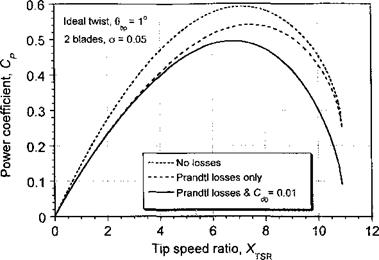
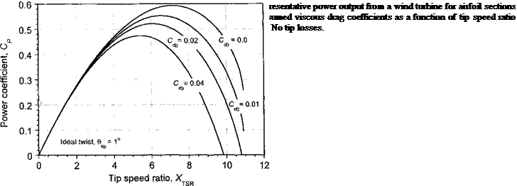
The separate effects of viscous drag and Prandtl tip losses on the turbine power output is shown in Fig. 13.15. Notice that both types of nonideal losses tend to decrease power output (decrease turbine efficiency). Taken together they comprise about a 15% loss of efficiency, which is fairly close to the results obtained in practice for operating conditions that do not involve any blade stall (see Fig. 13.6).

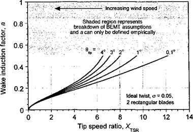
Of interest is the induced velocity or axial induction factor a as a function of tip-speed ratio. In the ideal case (hyperbolic blade twist) the induction factor is uniform over the disk. The behavior of the induction factor is shown in Fig. 13.16 for several blade pitch

Tip Losses and Other Viscous Losses

Figure 13.15 Turbine power output as a function of TSR showing the separate effects of viscous drag and Prandtl tip losses.

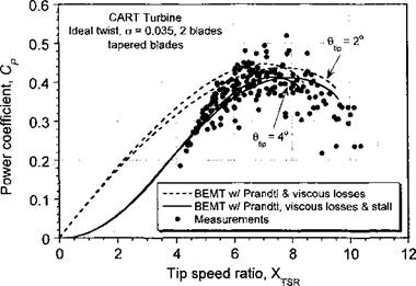
angles. Notice that the largest induction factors arc obtained at the highest tip speed ratios (lowest wind speeds). This is because the induced velocity is a relatively high fraction of the wind speed at low wind speeds (high values of Xtsr) and becomes an increasingly smaller fraction as wind speed builds (low values of Xtsr)- Furthermore, at low wind speeds there is a possibility of two flow directions existing at the rotor disk, which can only be represented, albeit approximately, using an empirical relationship between Cj and a, as previously discussed. Another factor that limits the applicability of the BEMT is that at higher wind speeds there is the possibility of blade stall, which also needs to be considered if the induction factor is to be predicted accurately.

Tip Losses and Other Viscous Losses

Figure 13.16 Variation of axial induction factor as a function of TSR for a wind turbine with ideally twisted blades giving uniform induction factor.

Tip Losses and Other Viscous Losses

Figure 13.17 Turbine power output as a function of TSR showing the effects of blade

stall. Data source: Measurements from two-bladed wind turbine, courtesy of NREL.

Tip-Loss Effects

The induced nature of the vortical wake and its effects on the spanwise loading on the blades can be approximated using Prandtl’s tip-loss function as shown previously for the helicopter rotor in Section 3.3.10. Because the basis of the BEMT is a strictly “2-D” theory, 3-D effects such as the physical roll-off in the lift as the blade tip is approached must be treated using corrections, although the better approach is to use lifting-line and vortex theory (see Section 13.11). The Prandtl correction can account approximately for a finite number of blades and also for variations of blade planform and twist through the effect on the inflow angle.

Prandtl’s “tip-loss” result can be expressed in terms of a correction factor F to the change in momentum over the annulus of the disk in Eq. 13.55 such that

dCj = 8F(1 — a)ar dr where F = (— j arccos (exp(—/)), (13.55) where the exponent / is given in terms of the number of blades and the radial position of the blade element r by

Подпись: (13.56)z r<p / z л — a J

If root losses are also to be modeled, then it will be apparent that the corresponding equation for / is

Tip-Loss Effects

Tip-Loss Effects

(13.57)

where ro represents a root cut-out distance, which represents the lack of aerodynamic lift – producing surfaces close to the hub. With the incorporation of tip – and root-loss effects into
the BEMT the induction factor becomes

Подпись:O^TSR Q, , 12 _ aXTSRClg(XTSRer + l)

16 F + 2J 8 F

Подпись:Tip-Loss Effects(13.58)

Because F is not known a priori, in the first instance Eq. 13.58 is calculated from the inflow angle (or induction factor) after assuming that F = 1. Repeating the calculation for a and F using Eqs. 13.58 and 13.55 shows rapid convergence, normally within 3 to 10 iterations.

Подпись: oXTSRCia(XTSR6r + 1) 8 F Подпись: > Подпись: 12 16F 2/ Подпись: (13.59)

The numerical process for including the Prandtl tip-loss function will fail, however, if the square-root term in Eq. 13.58 produces an imaginary result, that is, if

This means that the inclusion of the Prandtl tip-loss factor can limit the range of wind speeds and operating conditions over which numerical solutions can be found using the BEMT simply because the governing equation breaks down numerically as a becomes greater than 0.5. This problem can be circumvented if the relationship between induction ratio and thrust is represented using the empirical branch of the curve for a > 0.5, say when using Eq. 13.15 because of its simple analytic form (see also Fig. 13.4). While this assumes that the induction ratio is constant (or almost so) over the disk, for any values of a approaching 0.5 this means that multiple flow directions are possible and so there is a decreasing validity of the momentum theory, in general. In this case, the fundamental equation for a must be rederived, such as using Eq. 13.15. In this case, equating the momentum and blade element results gives

(8(a – l)a + 4) F = oX^Qr = (Хта0г + (1 – o)), (13.60)

which after manipulation can be expressed in the analytic form

а2 + – Л a + (1 – + ])) = 0. (13.61)

8 F ) 2 8 F )

This has the solution

iy /1 oXTSIQ.(X„„er+l)

a(.r, XTsl, F) = ^-1^–J —————- — ————

_ /O^tsrQ, _ i

A 16F ?/’

—— — /

This modified equation is valid for the extended range 0.5 < a < 1.0, where it should be understood that it is based on an underlying empirical assumption and an extension of the Prandtl tip-losses concept to flow conditions where the assumptions inherent in the BEMT become increasingly questionable. Nevertheless, in light of the results obtained (see next section) its use seems appropriate for engineering purposes because it allows the BEMT to be used for wind turbine analysis over a wider range of practical operating conditions.

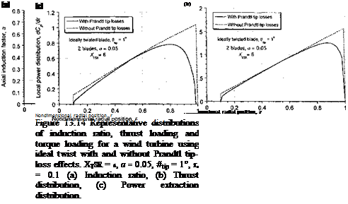
Representative calculations of the spanwise distribution of induction ratio, thrust distri­bution and distribution of power extraction on a wind turbine as predicted using the BEMT

Tip-Loss Effects

are plotted in Fig. 13.14. The results are shown with and without the Prandtl tip and root losses and for a case where locally near the tip a is greater than 0.5. Notice that the tip – (and root-) loss function serves to increase the induction ratio over much of the blade, in part because the blade in this case is not of particularly high aspect ratio (R jc = 10). These “tip losses” decrease the thrust on the turbine and also decrease its power output. Because most of the net airpower generated by the turbine comes from stations toward the blade tip, it is apparent from Fig. 13.14(c) that tip effects are really a very substantial source of aerodynamic losses and modeling the effects accurately is of fundamental importance. The use of vortex theory, such as with the use of a lifting line and a trailed vortex wake, is a more physically pleasing way of modeling such losses (see Section 13.11).

Effect of Number of Blades

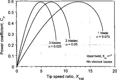
The variation in power output with TSR from a wind turbine is affected by the number of blades. If there are no nonideal losses to consider, the resulting behavior is typified by Fig. 13.12. Notice that increasing the number of blades (or increasing solidity) does not affect the maximum efficiency of the turbine, but it does affect the tip speed ratio (or wind speed) where maximum efficiency is obtained. Increasing the number of blades or solidity also reduces the range of tip speed ratios over which high power coefficients can be obtained. Too many blades or too much solidity gives a steep power curve that peaks at low tip speed ratios. This is not very useful in practice, besides the fact that the blades will also be approaching stall at these conditions (high wind speeds). The addition of viscous drag (see Section 13.8.2) changes the situation somewhat and the efficiency will decrease with increasing numbers of blades (increasing solidity). There is no effect on efficiency if the solidity is kept constant and only viscous drag is assumed. However, consideration of tip losses (see Section 13.8.3) will tend to favor turbines with larger numbers of blades (for a given overall solidity) because this will minimize tip-loss effects (i. e., induced losses will be minimized and the turbine will be closer to an ideal actuator disk).

Figure 13.13 shows how the power output from a wind turbine depends on the viscous drag of the airfoils that comprise the blades of the turbine. Clearly maximum efficiency favors airfoils with lower drag coefficients, all other factors being held constant, but this is rather obvious. At the Reynolds numbers encountered on wind turbines most airfoils tend to have drag coefficients in the range 0.01 < < 0.02 unless surface finish

is degraded by erosion, dead insects, frost, or ice. Some airfoil sections are more sensitive to these effects than others. The absence of specific information on the airfoil section characteristics from measurements would suggest the use of Cd0 = 0.01 as an initial assumption for preliminary design studies.

Blade Element Momentum Theory for a Wind Turbine

The blade element momentum theory (BEMT) is a hybrid method that exploits the fundamental equivalence between the circulation and momentum theories of lift. With certain assumptions, the BEMT allows the induction factor along the blade to be estimated. Thereafter, all the other airloads can be determined. The BEMT allows a clear examination of the principal design factors that influence wind turbine performance and design. How-

pvp. r the. RFMT яппгпягЬ ap. np. rallv crivp. fi яггрпїяКір яппгпуітягігтс tn tbp яуіс/ттМлр

~ —>—**-.* C?- * Trv^*«lUVIVlIU W liUUWUXV

distribution of inflow and loads found under conditions where the wind is normal to the plane of the turbine (i. e., the turbine is unyawed with respect to the oncoming wind).

The BEMT allows for the turbine inflow to be solved for based on satisfying a combina­tion of a momentum balance on successive annuli of the turbine disk and a blade element representation of the sectional aerodynamics. The underlying principle is, of course, that each section behaves as a 2-D airfoil, which implies that the spanwise loading gradients are small. This is a reasonable assumption to make in light of the good comparisons shown previously in Fig. 3.19 between the BEMT and the vortex theory for the helicopter problem. Fundamentally, the limitations of BEMT soon become clear, but the value of BEMT to the engineer is determined by how well it really works in practice. The additional value of BEMT is that it allows a fundamental understanding of the effects of varying geometri­cal and aerodynamic parameters on the performance of a wind turbine (or on a rotor, in general).

On the basis of the differential momentum theory developed in Section 3.2, we may compute the incremental thrust on an annulus of the turbine disk. In this case the mass flow rate through an annulus of the disk is

dm = pdA(Voo – = 2np{VO0 – v()y dy, (13.41)

so that, using the differential form of Eq. 13.12, the incremental thrust on the annulus is

dT = 2p (Voo – Vi) VidA = 4жр (Voo – Vi) v(y dy. (13.42)

Blade Element Momentum Theory for a Wind Turbine

In coefficient form (again with r = y/R) this is simply

Blade Element Momentum Theory for a Wind Turbine Подпись: afar dr Подпись: (13.51)

should be apparent. After the induction factor is obtained, the rotor thrust and power may then be found by integration across the rotor disk using

Blade Element Momentum Theory for a Wind Turbine Подпись: (13.52)

and

Blade Element Momentum Theory for a Wind Turbine Подпись: (13.53)

Notice that the power can be expanded to show the separate components produced by the forward inclination of the lift components on each blade element less the profile losses from viscous shear, giving

In the ideal case where a is uniformly distributed over the disk, and it is assumed that Cd — Cda, then

Подпись: 3 drCp — oX3 f фС[Г3 dr — oX3 f Cdr3

r TSR I ^ 1 TSR / a

Blade Element Momentum Theory for a Wind Turbine Подпись: (13.54)

Jo Jo

where the first term is the correct result for the induced power based on the simple momentum theory. The second term depends on the blade area (solidity) and the drag coefficient of the airfoil sections and is analogous to the profile power term that appears in the helicopter case. It is significant that this term also depends on the tip speed ratio.

There are two points of interest in Eq. 13.50. The first is the distribution of blade twist that results in uniform inflow (uniform value of induction factor) over the turbine disk. It will be apparent that for a given tip speed ratio this can only be obtained if the product Or — constant, which, by analogy with the helicopter result (Section 3.3.3), is known as ideal twist, that is, 6(r) = 6tp/r. This form of blade twist is identical to the distribution necessary for the efficient operation of a helicopter in hovering flight and will also give the lowest induced losses on the wind turbine (i. e., the most efficient energy extraction). Notice that the form of the distribution of blade twist for maximum efficiency is independent of tip speed ratio but that the magnitude of the blade twist will be dependent on the tip speed ratio (i. e., the amount of twist will affect the range of tip speed ratios over which the turbine can operate efficiently). Second, it has already been shown by means of the simple momentum theory that a = 1/3 in the condition for the maximum energy extraction from the wind. For variable pitch turbine blades this allows Eq. 13.50 to be solved for the blade pitch at a given tip speed ratio (or wind speed for a given rpm) to yield maximum aerodynamic efficiency, and thus maximum energy extraction from the wind.

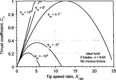
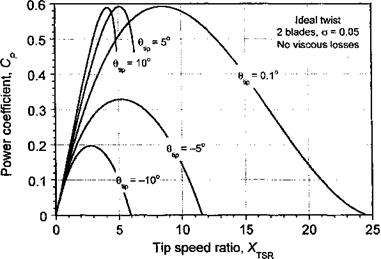
Representative results from the BEMT are shown in Figs. 13.10and 13.11 for a rotor with ideal blade twist operating at different blade pitch angles. No nonideal losses are assumed in this case, (i. e., only ideal-induced losses are present). From results such as these, the power coefficient at a fixed rotor speed can be derived for different wind speeds. For variable pitch

Blade Element Momentum Theory for a Wind Turbine

Figure 13.10 Representative thrust produced on a wind turbine as a function of tip speed ratio using the BEMT for various pitch angles. No nonideal losses.

turbine blades, the power coefficient can be determined over a range of pitch angles and wind speeds. It is seen that a shallow blade pitch allows for energy extraction over a wide range of wind speeds; neither large positive nor negative pitch angles allow for efficient operation. Recall that the BEMT is valid only for values of 0 < a < 0.5, so the curves cannot be defined for all wind speeds and all pitch angles unless empirical corrections are used (see Section 13.8.3).

Blade Element Momentum Theory for a Wind Turbine

Figure 13.11 Representative power output produced from a wind turbine as a function of ’ tip speed ratio using the BEMT for various pitch angles. No nonideal losses.

Blade Element Momentum Theory for a Wind Turbine

Figure 13.12 Representative power output produced from a wind turbine for different numbers of blades as a function of tip speed ratio using the BEMT. No nonideal losses.

Blade Element Model for the Wind Turbine

The aerodynamic analysis of the wind turbine can be approached readily from the perspective of the blade element model, which has been discussed previously in Chapter 3 for the helicopter. In this case, the flow model is similar to the helicopter rotor in a descending flight condition (discussed in Section 2.13.2), with the flow upward toward the plane of the


Blade Element Model for the Wind TurbineBlade Element Model for the Wind Turbine

Blade Element Model for the Wind Turbine

Подпись:Подпись: ІПодпись: У(a) Front view

Blade Element Model for the Wind Turbine

Qy

R

У

z®———— ►x

Blade Element Model for the Wind Turbine

Figure 13.9 Blade element model for a wind turbine operating in axial (unyawed) flow.

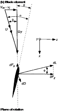
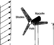
rotating blades, as shown in Fig. 13.9. The local pitch angle of the blade element is в so that the AoA at the blade element[47] is a = в + ф. The inflow modifies the direction of the relative flow velocity vector and, therefore, alters the AoA at each blade element from its 2-D value. It will be apparent that it is the forward inclination of the lift vector that provides a component of force to overcome the drag (profile and induced) on each element and so produces the net in-plane force that will drive the turbine and produce power at the shaft. This is analogous to the autorotational condition for the helicopter.

Assume that the swirl component in the flow near the turbine and its wake is small and can be neglected. The resultant incremental lift dL and drag dD per unit span on the blade element are

1 9 1 „ ___________________________________________________

dL = – pU cCi dy and dD = – pU*cCd dy, (13.26)

where Ci and Cd are the lift and drag coefficients, respectively, and the resultant flow velocity U ^ Qy. Wake swirl may be included into U, however, based on a knowledge of the helicopter flow field, swirl is small at lower thrust coefficients and/or higher tip speed ratios (see page 69). The lift dL and drag dD act perpendicular and parallel to the resultant flow velocity, respectively. Notice that the quantity c is the local blade chord. From Fig. 13.9

it is apparent that these forces can be resolved perpendicular and parallel to the rotor disk plane giving

dFz = dL cos ф + dDsiiup and dFx = dL sin0 — dDcoscp. (13.27)

The contributions to the thrust, torque, and power of the rotor are thus

dT = Nb dFz, dQ = Nby dFx and dP = NbQy dFx, (13.28)

where Nb is the number of blades comprising the turbine rotor. This also assumes no precone on the blades, which can be significant for wind turbines. Such effects can be approximately incorporated by multiplying dCT by cos fP, where f>p is the precone angle. Furthermore, notice that unless the turbine is yawed with respect to the wind, the aerodynamic environment is (ideally) axisymmetric, and the airloads are independent of the blade azimuth angle and that there is no wind shear. Substituting the results for dFx and dFz from Eq. 13.27 gives

dT = Nb(dL cos ф + dD sirup), (13.29)

dQ = Nb{dL sixuf) — dD cos ф)у, (13.30)

dP = Nb(dL sin0 — dDcos(f>)Qy. (13.31)

Applying small angle simplifications to the preceding equations (see page 118) gives

dT = Nb{dL + <f>dD), (13.32)

dQ = Nb(4>dL – dD)y, (13.33)

dP = NbQ((f>dL – dD)y. (13.34)

me incremental thrust coefficient on the turbine then

Подпись: (13.35) (13.36) _ NbdL _ Nb(jp(Qy)2c(Ci +.pCd) dy)

T ~ {pAVl ~ p^R2)V^

= (Q + фСа) dr = oX2(Q + фСа) dr,

where r = у/R,(7 = Nbc/irR is the local or chord solidity of the rotor and X — Qy/Voo is the local section speed ratio. It will be apparent that the local section speed ratio can be written as

Подпись:у _ Qy _ QR Ґ Qy _ _

Voo Voo S2R)

Therefore, the incremental thrust coefficient becomes simply

ИГг = гтУ2 (Г. 4- ЛГ Лг2 Иг

——- ± TSRV“‘ ‘ ^———————–

Proceeding in a similar manner to find the incremental power coefficient dCp leads to

Подпись: (13.39)dCp = о(фСі — Cd)r3 dr.

Подпись: ф = tan Подпись: Poo Vi Qy
Blade Element Model for the Wind Turbine Blade Element Model for the Wind Turbine

It will also be apparent that the inflow angle can be written as

(13.40)

The fundamental equations for the analysis of the wind turbine by means of the blade element theory have now been established. However, to evaluate Cp and Cp it is necessary to predict the spanwise variation in the induced inflow u, (or the induction ratio a) as well as the sectional aerodynamic force coefficients, Q and Cd – Also, a = «(Voo, 0, u,), and Vi = vfr). As for the helicopter, clearly a fundamental problem for the wind turbine is to determine the induced velocity Vi (or a), which has its origin for the most part in the physics of the downstream wake. This aside for now, if 2-D aerodynamics are assumed, then Q = Ci(a, Re)mdCd = Q(a, Re), where Re is the local Reynolds number.[48] See Tangier (2002) and Coton et al. (2002) for a discussion of how 2-D airfoil measurements can he integrated into the blade element approach and the various practical problems associated with this. Because these airfoil section characteristics cannot, in general, be expressed as simple analytic results it is usually necessary to use table look-up approaches (Section 7.11.3) and to solve the integrals for CT and Cp by numerical integration. However, it is possible to proceed further by assuming linear aerodynamics and by invoking the principles of the blade element momentum theory. This has been discussed in Section 3.3 for the helicopter.

Elementary Wind Models

Primary aerodynamic factors affecting power output from the wind turbine are the wind speed, the equivalent density altitude at which the turbine operates, and the tower height, that is, the height of the turbine (measured by its shaft position) off the ground in the ground surface boundary layer. Additional factors include the likelihood of large amplitude fluctuations in wind speed (gusts) and the associated turbulence in the wind. Altitude and temperature affects the density of the air flowing through the turbine, and the effect on power output can be calculated using the standard atmospheric model given in Section 5.2. The height of the tower, h, is important because the turbine operates within the atmospheric boundary layer at the ground, which can have a substantial velocity gradient depending on the upstream terrain – see Fig. 13.8. The effect of this boundary layer is to reduce the mass flow through the turbine and so reduce its power output. The consideration of this effect is very important for choosing the site for the wind turbine. To size the rotor it is necessary to know the energy content of the winds at the proposed site and at the proposed height of the

Figure 13.8 A wind turbine operates in an atmospheric boundary layer.

turbine off the ground. Such data must be acquired over many years to establish confidence that the proposed site will indeed provide the average power desired from the turbine (or wind farm). Wind data is often measured in advance at proposed sites or is obtained by using historical wind data published in handbooks such as that compiled by Frost et al. (1978). So-called wind maps are often prepared using both measured data and statistical models.

In practice, two models are most often used to represent the variation of wind speed characteristics with height: the power law and the logarithmic law. The power law is written as

Elementary Wind Models

Подпись: I Tower Wind gradient Подпись: Wind Подпись: Tower
Elementary Wind Models
Подпись: JL.

(13.20)

Elementary Wind Models

where ftref is a defined reference height, which is usually taken to be 10 m (32.8 ft) above the ground. It seems common to assume either that m = 1/6 or m = 1/7, so it will be apparent that the average power output from the turbine will increase with h1/2 or ft3/7, respectively. The logarithmic law also includes a roughness length zo representing the character of the terrain upstream of the turbine such that

Подпись: (13.21)

These results are valid only for flat sites and where the atmosphere is not subjected to strong convection or thermal stratification effects. There are other types of models used for hill sites.

In addition to the effects on the mean wind speed there are also stochastic variations in wind speed, because of turbulence, which will affect the power output from the wind turbine. Such variations have been measured using anemometers and the data have been developed into statistical models. It is usual to represent the wind speed as an average (or mean) component U plus a temporal or fluctuating component u, that is,

Подпись: (13.22)Voo(f) = U + u(t).

Table 13.1. Coefficients of Atmospheric Boundary Layer Model

Type of terrain

го (m)

m

Open country

0.02

0.12

Rural with few trees

0.05

0.16

Rural with trees and towns

0.3

0.928

Open water

0.001

0.01


I


The turbulence intensity Iu is written as a root-mean-square of the fluctuating wind speed and is defined by


Elementary Wind Models

(13.23)


Iи =


where T is the time interval over which the turbulence is measured. While various standards are used, T =10 minutes is common. It is found that in practice Iu varies between 0.1(7 and 0.2(7 with the higher values being typical of rough upstream terrain. The value of Iu also varies with height h and decreases away from the surface. Furthermore, lu is generally larger at low wind speeds than at high wind speeds. Custom turbulence spectra are often used to model the wind turbulence characteristics at specific wind farms. The mean wind speed, U, is modeled statistically using either the Weibull or Raleigh statistical distribu­tions – see Eggleston & Stoddard (1987). Here, the wind speed is expressed in terms of a probability distribution, p(Voo). When combined with the wind flow statistics model, the average airpower P generated by the wind turbine is


P =


(13.24)


РІУаоЖУоо) dV, oo


This average power is then used to derive a capacity factor


Capacity factor =—————— ,

Rated power


(13.25)


which is normally less than 50% for most wind sites. The accurate prediction of the capacity factor is particularly important jn evaluating the overall economics of a wind farm.

It is clear from the published literature, however, that further work needs to be done to better describe wind characteristics by mathematical models and to integrate them into turbine design methods. Premature failure of commercial wind turbines is, in part, traceable to uncertainties in wind estimation and underprediction of structural loads on the blades, shaft, and so on. Some wind models use only the turbulent component normal to the disk and this is a concern in wind turbine design because lateral and vertical wind gradients are also a source of unsteady loads – see Hansen & Butterfield (1993). Walker et al. (1989) give a review of the various practical issues in the use of wind models.


Representative Power Curve for a Wind Hirbine

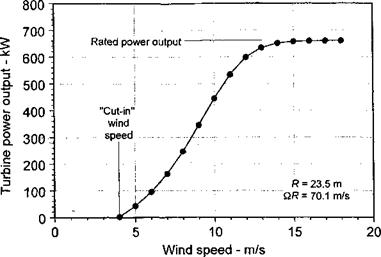
The amount of power produced by a wind turbine as a function of wind speed is obviously of primary importance for design. A representative power curve is shown in Fig. 13.5 for a large 47 m (154.2 ft) diameter turbine that has a rated electrical power output of 0.66 MW (885 hp) at 28.5 rpm. First, notice that there is a “cut-in” wind speed below which the turbine produces no power. This is, in part, because of the need to overcome mechanical friction in the system, which will require some minimum wind speed before the turbine starts to produce useful power. Also, there are aerodynamic losses to overcome that have their origin in viscous effects. This is because the turbine first starts to operate at high angles of attack with stall on the blades and the net wake flow is also in the turbulent wake state where there are rotational energy losses in the flow. Therefore, a minimum wind speed is required to overcome these losses. Second, notice from Fig. 13.5 that, after power is being produced, the output increases rapidly and is essentially proportional to V^, as would be expected based on Eq. 13.1.

Third, as a certain wind speed is reached, it will be noted that the power output levels out and approaches a limit known as the rated power output. This power limiting is done using one of a variety of strategies to ensure that the turbine does not absorb more power from the wind than could be absorbed by the electrical generator operating at its maximum continuous rating. One strategy is to use blade pitch control, where the blade pitch angle is adjusted automatically to match the power output to the wind speed. At higher wind speeds, the blades can be feathered to stall the blades and thus to prevent a runaway condition. At very high wind speeds or in storms, the blades can be feathered into a parked position, slowing or stopping the turbine and cutting its power output completely. Alternatively a mechanical or aerodynamic brake (such as spoilers) can be used instead of pitch regulation. For small wind turbines another technique is used to turn the rotor out of the wind to cut its energy production. This is known as furling – see Muljadi et al. (1998) and Eggers et al. (2000) for a discussion of furling and approaches to its aerodynamic modeling.

Representative Power Curve for a Wind Hirbine Подпись: turbine tip speed SIR wind speed Voo Подпись: (13.19)

The power curve for a wind turbine may be plotted as a power coefficient CP versus wind speed or more usually as CP versus tip-speed ratio (TSR). For a wind turbine the tip speed ratio XTSR is defined as

This parameter is essentially the reciprocal of the rotor advance ratio used in helicopter work and it is important that the two parameters are not confused. For the results shown

Representative Power Curve for a Wind Hirbine

Figure 13.5 Power output from a representative constant tip-speed wind turbine as a function of wind speed.

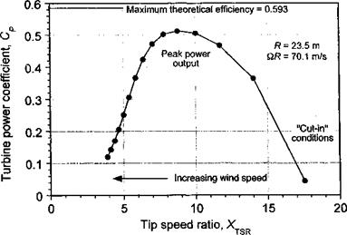
in Fig. 13.5 the corresponding airpower Cp versus XTSR curve is shown in Fig. 13.6 when al­lowing for a 90% electrical-mechanical conversion efficiency in the measurements. Notice also that the aerodynamic efficiency reaches a peak of almost 85% of the theoretical max­imum when the turbine is operating at its rated speed. This suggests a very well-designed turbine in this case, but will generally be typical of large modem designs.

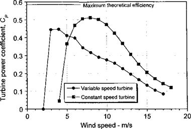
However, it will be apparent from Fig. 13.6 that peak efficiency for a constant speed (rpm) turbine is obtained only over a very narrow range of wind speeds (i. e., at a single TSR). This means that, conversely, this type of wind turbine does not operate at peak aerodynamic

Representative Power Curve for a Wind Hirbine

Figure 13.6 Representative power coefficient versus tip-speed ratio curve for a constant speed (rpm) horizontal axis wind turbine.

Representative Power Curve for a Wind Hirbine

Figure 13.7 Representative power coefficient versus wind speed curves for constant speed and variable speed types of horizontal axis wind turbines.

efficiency over a very wide range of wind speeds.[46] This is a disadvantage of the constant speed type of wind turbine, despite its mechanical simplicity. However, not all wind turbines are designed to operate at constant tip speed or with constant blade pitch. Smaller wind turbines are often designed to run over a range of tip speeds and can exhibit more efficient energy extraction at lower wind speeds, as shown in Fig. 13.7. The disadvantage, however, is that the aerodynamic efficiency of a variable speed turbine drops off quickly at higher wind speeds. Yet at high wind speeds the loss of efficiency also serves to regulate the turbine’s power output. The most common type of wind turbine in use today is the large variable speed turbine, where the power efficiency is fixed below the rated wind speed by electrically controlling the generator torque.

Theoretical Maximum Efficiency

Because both the thrust and power coefficients are functions of the induction factor, a, it is useful to seek the condition that corresponds to the maximum power output from the wind turbine. Differentiating Eq. 13.11 with respect to a gives

I /П

—- = 4(1 — 4a + 3a2) = 0 for a maximum. (13.17)

da

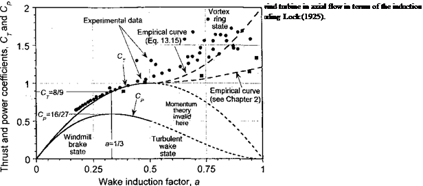
By inspection it is apparent that this condition is met when the wake induction factor a = 1/3 and the corresponding values of Ct and Cp are 8/9 and 16/27, respectively (see Fig. 13.4).

In summary, this means that at the most efficient operating condition then 1 8 16

a = -, CT = – = 0.89 and CP = — = 0.59. (13.18)

3 9 27

This operating condition is known as the Betz-Lanchester limit – see Glauert (1935,1983) and Bergy (1979). This condition gives the upper theoretical limit to the aerodynamic power (or airpower) that can be extracted by a conventional wind turbine, assuming no viscous or other losses. In practice it is found that airpower values of Cp of between 0.4 and 0.5 are typical of a modern wind turbine when at its design operating state. This suggests that a wind turbine has a maximum possible aerodynamic efficiency of between 66% and 83% (when compared to the maximum possible airpower extraction based on the simple momentum theory) and is comparable to the aerodynamic efficiency of a helicopter rotor in producing thrust for a given shaft power input.

Power and Thrust Coefficients for a Wind Turbine

Using Eq. 13.7 with Eq. 13.3 and expanding out gives

P = 2pA (Vqc — Vi)2 Vi. (13.9)

Подпись: CP Power and Thrust Coefficients for a Wind Turbine Подпись: (13.10)

We now define a power coefficient (different to that used for a helicopter) in terms of the wind speed as a reference such that

Подпись: CP Подпись: 2pA(Vo0 - v,) = 4(Уос - Vjfv, 'jpAV^ VI Подпись: 4(1 - of a. Подпись: (13.11)

so that

The relationship in Eq. 13.11 is shown graphically in Fig. 13.4 and can strictly be valid only for 0 < a < 1/2 to avoid violating the assumed flow model by having the possibility of both downstream and upstream flow directions. We can also find the thrust coefficient acting on the turbine. Using Eq. 13.3 then the thrust is

Подпись: (13.12)T — mw = pA(V, oo – vi)w = 2pA(Voo – vfivi

Now, defining the corresponding thrust coefficient as

Подпись: Cp =Подпись: 2 pAfVoo ^i)^i JPAVIPower and Thrust Coefficients for a Wind Turbine(13.13)

Power and Thrust Coefficients for a Wind Turbine Power and Thrust Coefficients for a Wind Turbine

means that

which is also shown in Fig. 13.4 but again the result is valid only for 0 < a < 1/2. Notice further that Cp = (1 — a)Cp in this case. Also shown in Fig. 13.4 is an empirical result for Cp in the range 1/2 < a < 1 (i. e., turbulent wake region) often attributed to the analysis of Glauert (1926), but see also Lock et al. (1925). Another fit based on the results described in Section 2.13.3 and shown in Fig. 2.18 is also given. Eggleston & Stoddard (1987) suggest

replacing Eq. 13.14 by Cj = 4a 1 — a for a > 0.5 but this is obviously incorrect. A more satisfying approximation to use is

CT =4(a-)a+2, (13.15) although various other empirical equations seem to have been used [see Burton et al. (2001) and Buhl (2004)]. While this and other such equations mimic the results that have been measured (or estimated from measurements) in this regime, they are not based on any physical rationalization of the flow state associated with the increased thrust in the turbulent wake or vortex ring state (VRS). Some other results in this region can be deduced from the complete induced velocity curve shown previously in Fig. 2.18, where it will be apparent that Ct and a in the wind turbine case are related to the climb and induced velocity of the rotor using

Подпись:Подпись: CT =4Подпись: -і

Power and Thrust Coefficients for a Wind Turbine

(13.16)

Therefore, the Ct versus a curve given by Eq. 13.15 is simply an alternative empirical realization of the portion of the complete induced velocity curve that cannot be defined theoretically using momentum theory.

Momentum Theory Analysis for a Wind Turbine

The aerodynamic modeling of wind turbines has spanned the entire range of meth­ods used for helicopter rotors, from engineering models based on blade element-momentum theories, through traditional blade element models combined with inflow or vortex wake theories, to computational fluid dynamics (CFD) methods that solve numerically the Euler or Navier-Stokes equations from first principles. The most fundamental level of analysis of the wind turbine is by means of the classical momentum theory, first developed by Betz & Lock [see Glauert (1935, 1983)]. This one-dimensional approach is very similar to the descending helicopter problem examined in Section 2.13.2. In this case, however, the thrust from the wind turbine is not known a priori and will be a function of the wind speed, rotor speed (rpm), and blade pitch. This means that the problem cannot be solved uniquely using momentum theory by itself and, at a minimum, the blade element theory combined with the circulation theory of lift must be used. The momentum analysis of a wind turbine allows for a first level analysis of the power produced for a given wind speed, however, and can be used to determine the conditions under which the maximum energy conversion from the wind can be obtained.

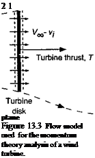
A 1-D model of the control volume surrounding a wind turbine is shown in Fig. 13.3. The wind speed is V^, with the induced velocity in the plane of the turbine being v, . Notice that, to avoid any ambiguity, it is assumed that the velocity is measured as positive when in a downstream direction. At the plane of the turbine, the net velocity is Vqo — vt. In the far wake (well downstream of the turbine) the velocity is Vqq — w. Notice also that because a wind turbine extracts energy from the flow, the velocity decreases downstream of the turbine, From continuity considerations the slipstream boundary (wake) must, therefore, expand. By the application of the, principle of the conservation of mass, the fluid mass flow

rate, m, through the turbine disk is

m = рАІУоо – ы). (13.3)

The change in the momentum of the flow across the disk can be related to the thrust by

T – mVoc-m (Voo – w) ■ (13.4)

Expanding out this equation gives a relationship for the thrust on the turbine in terms of the velocity deficit in the turbine wake, that is,

Подпись: /1 о r- уи.Э) ru V 00 “T Г ft W — rriuu.

The power output from the turbine can be obtained by conducting an energy balance for the system. Basically the work done on the flow to change its kinetic energy must be extracted by the turbine, assuming no viscous or other “nonideal” losses at this stage. The work done on the air by the turbine per unit time, W, is given by

l,1,1 1

W = – m (Voo – w)2 – – mV£ = ^rnw{w – 2УЖ) = –mw {2У(у0 – w).

(13.6)

Notice that the turbine does negative work on the air (i. e., it decreases its kinetic energy). Therefore, the turbine extracts power from the airstream and this operating condition is known as the windmill state, for obvious reasons. More usually this state is referred to as the windmill brake state because the turbine in this condition decreases or “brakes” the wind velocity. This means that the power output from the turbine is positive and so

P = T (Voo – ^mw (2Voo – w). (13.7)

Substituting Eq. 13.5 into Eq. 13.7 gives

T (Voo ~ Vi) = іmw (2Voo ~ w) — mw (V» – vt), (13.8)

from which it is apparent that w = 2d,- or u, = w/2. This is the same relationship found for the helicopter in axial flight, as discussed in Section 2.13.2, and so in this case from

Direction

Подпись:of positive———————— ►

velocity

Подпись:00

Free-stream

flow

Far downstream

continuity considerations the wake expands downstream of the turbine. It is also apparent that, for the assumed flow model in Fig. 13.3 to be valid, then Vqo — ш > 0 or alternatively that Voo > |w| > 2|i)j|. If this is not satisfied then there is the possibility of two flow directions in the flow near the turbine disk and a unique control volume encompassing only the limits of the disk cannot be defined. This is equivalent to helicopter rotor operation in the turbulent wake and vortex ring state (see Section 2.13.6), for which no exact solution can be found by means of the momentum theory.

In the case of the wind turbine, its thrust is not known (or defined) a priori like in the heli­copter problem. Therefore, it is not possible to find the performance of the turbine as a func-

Подпись: 711-1/4 cnoorlПодпись:Подпись:IV* nr»,a /o1n#a rxf ІпгЬіГ’АґІ /аі r»r*i t; ‘TbArAfrvtv*

rviviviiw VU1UV Vi. XUUUWU T ViWl LJ. JLliVi V1V1W)

in the analysis of a wind turbine it is usual to define an induction ratio a as the independent parameter such that a = Uj/ Voo or that и,- = a Vqq. The thrust and power output can then be established as a function of a, if this value can be found (calculated). It will be apparent that the larger the value of a the more the flow is slowed as it passes through the turbine.