Category Principles of Helicopter Aerodynamics Second Edition

Power in the Wind

Power in the Wind Power in the Wind Подпись: (13.1)

The purpose of a wind turbine is to capture the energy of the wind and convert it into useful energy, usually in the form of electrical energy. Consider the kinetic energy of a wind of velocity Vqo as it passes through a disk of area A in the atmosphere. If the disk is normal to the wind vector, then the mass flow rate through the disk will be m = pAVoo and so the kinetic energy per unit time contained in the wind that flows through this disk is

This is equivalent to the power that could be extracted from the wind assuming the energy conversion process was 100% efficient. A modem turbine may extract only half of this potential energy because of aerodynamic and mechanical losses (see Section 13.4). Notice from Eq. 13.1 that the potential power output from the turbine is proportional to the square of its size (diameter) and cube of the wind speed.

For example, consider a wind turbine of 5 m (16.4 ft) in diameter with a net efficiency of 50% that operates with its disk properly pointed perpendicular to a wind of speed of 10 m/s (32.8 ft/s) at standard sea level conditions. The potential power output will be

P = (0.5) x A і Tool3 = 0.25 x 1.225 х(7г2.52)х(і0)3 «okWorBhp. (13.2)

This example shows why wind turbines have to be very large in size (diameter) and have to be located where the wind blows on average at relatively high speeds. Wind turbines are often situated in groups or farms with many tens or hundreds of turbines to produce a sufficiently useful and economically attractive net power output.

Notice that if the turbine is not pointed into the wind then it will be apparent that the velocity normal to the disk will be reduced by a factor cos у, where у is the yaw angle. In

such a case, according to Eq. 13.2 the power output drops by cos3 */ and so the importance of accurately controlling the orientation of the turbine relative to the wind direction becomes immediately clear. This must be done by design or by some sort of mechanical control device that senses wind direction and automatically points the turbine accurately into the wind.

History of Wind Thrbine Development

The power of the wind has been used by humankind for millennia (e. g., sailing ships). Wind turbines are more recent machines, but the basic concept dates back many centuries with primitive forms being used in Babylonian times – see Shepherd (1990). More advanced wind turbines were used by the Persians in the seventh century and had become more widespread in Europe by the fifteenth century. The most common machine was the tower mill, which was used for grinding and milling grain. These windmill machines underwent systematic improvements by trial and error and, by the seventeenth century, had evolved into a surprisingly high level of sophistication, to the point of using twisted blades with tapered planforms and control devices to point the windmill into the wind automatically. This suggests a good empirical knowledge of aerodynamics that was well in advance of the contemporary scientific understanding. Dutch settlers brought the windmill to the Americas in the eighteenth century. Another common windmill variant, the American fan mill, saw widespread use throughout the nineteenth and twentieth century for pumping water on ranches. By the beginning of the twentieth century, wind turbines were being used commercially to generate electrical power, although on a relatively small scale. The last century has seen considerable development in wind turbine technology, especially in Europe where energy costs are relatively high compared to the United States. The oil crisis during

History of Wind Thrbine Development

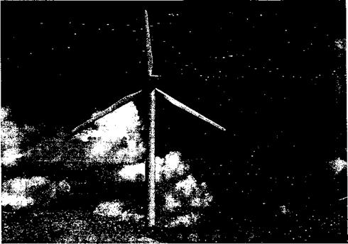
Figure 13.1 A modem three-bladed wind turbine. Source: Photo courtesy of Sandia Na­tional Laboratories.

the 1970s saw some new efforts to develop renewable energy resources in the United States, including wind energy. Today wind turbines are playing an increasing role in the generation of electrical power worldwide; concerns about global warming and the storage of waste from nuclear power plants have placed an increased emphasis on wind energy. As of 2005, the estimated global capacity for the creation of electrical power from wind energy was in excess of 25 GW, representing about 2% of total energy demands; see Thresher (2002).

An example of a modem horizontal axis wind turbine (HAWT) is shown in Fig. 13.1. Wind turbines are distinguished according to the orientation of the rotor shaft axis; in this case the shaft is parallel to the ground. This is the most common type of wind turbine and is also often referred to as a “lift machine” (as opposed to a “drag machine”) because the power output comes from the generation of lift forces on the rotating blades. The HAWT sits on a tall tower, which may be either upstream or downstream of the turbine. In the downwind type the turbine axis naturally tries to align itself parallel to the wind, but these turbines do not always track the wind accurately. The tower also produces a wake (a tower “shadow”) in this configuration and this affects the aerodynamic AoA and airloads on the turbine blades, making them unsteady. The vertical axis wind turbine (VAWT) or Darrieus turbine [Darrieus (1931)] has seen less extensive use, although this machine has the advantage that it will generate power with the wind from any direction and a means of controlling yaw is not required. Another type of VAWT is the Savonius turbine [see Savonius (1931)], which is a drag machine. However, VAWTs tend to be less efficient compared to HAWTs but, more importantly, they are not easily scaled up to the large size required for commercial power production because of structural design difficulties and aeroelastic problems.

A modem commercial wind turbine (see Fig. 13.1) may range from as little as 5 m (16.4 ft) in diameter up to over 100 m (328 ft) in diameter. Small turbines produce power in

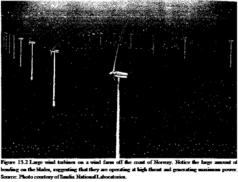
Подпись: Figure 13.2 Large wind turbines on a wind farm off the coast of Norway. Notice the large amount of bending on the blades, suggesting that they are operating at high thrust and generating maximum power. Source: Photo courtesy of Sandia National Laboratories.

the range from a few kilowatts, with the larger ones being in the megawatts capacity. Modem utility-scale wind turbines all have diameters greater than 50 m (164 ft). Many wind turbines are often seen together in a group known as a wind farm (see Fig. 13.2). Even in farms, however, the net cost of energy generated by wind turbines has historically been greater than that for power produced from fossil or nuclear fuels. Their unique aerodynamic and mechanical problems and overall difficulties in predicting the performance and structural loads on wind turbines has led to high capital investment, as well as to high operating and maintenance costs. Until recently, this has made it difficult for wind energy devices to compete with other forms of renewable and nonrenewable energy sources – see Hansen (1993). Today the costs of fossil fuels are increasing and wind energy costs are decreasing. The ever-increasing global emphasis on environmental issues also favors the use of wind turbines compared to more traditional forms of power generation.

Aerodynamics of Wind Turbines

It is some sort of tragedy that many get caught up in the idea of generating power from the wind and attempt to build machines before they have mastered the disciplines required.

D. M. Eggleston & F. S. Stoddard (1987)

13.1 Introduction

This chapter reviews some basic concepts associated with wind turbines and de­scribes their general operation and performance, focusing primarily on the aerodynamic issues. The overlap of fundamental problem areas between the helicopter rotor and the wind turbine is considerable. Clearly, the extraction of power from the wind using a tur­bine depends on its efficient performance and aerodynamic design, and in many ways the underlying principles of efficient design parallel those for helicopter rotors. In this respect, specialist engineers in both helicopters and wind energy can benefit from an appreciation of the particular technical issues found on both types of machines. This chapter, however, is not meant to be an all-encompassing treatise on wind energy or the aerodynamic principles of wind turbines. For this, the reader is referred to specialist books such as Walker & Jenkins

(1997) , Spera (1994), Burton et al. (2001), and Manwell et al. (2002).

While complicated in detail, the basic principle of a wind turbine is fairly simple. The wind blows through the turbine and turns the blades, converting the kinetic energy of the wind into rotational energy of the turbine. This rotational energy can be harnessed to produce useful work, usually in the form of electric power from a generator connected to the turbine shaft. The classic aerodynamic analysis of a rotor operating as a wind turbine was developed by Lock et al. (1925) [see review by Glauert (1935, 1983)]. Problems of the wind turbine that are common to the helicopter include understanding and predicting the unsteady blade airloads and turbine performance in both attached and stalled flows, as well as predicting the resulting structural loads and aeroelastic response of the rotating blades. However, there are unique differences as well. Wind turbines are subjected to complicated environmental effects that are not found on helicopter rotors. This includes ground boundary layer effects, atmospheric turbulence and large turbulent eddies, temporal and spatial variations in wind shear, thermal convection or stratifications, the possible effects of an upstream unsteady wake from a support structure (tower shadow) or even the effects of another wind turbine if situated in groups. The net effect is that wind turbines operate in an adverse, 3-D, unsteady (aperiodic) aerodynamic environment that is both hard to define using measurements and also to predict using mathematical models. This has led to difficulties in designing wind turbines that can operate reliably and economically over long periods of time.

The aerodynamic analysis of a wind turbine can be approached using classical momentum theory, the principles of which have been previously introduced in Chapters 2 and 3 for the helicopter. Although the helicopter rotor thrust can be defined uniquely a priori and the

momentum theory then used directly to determine the induced velocity, it will be shown that the classical momentum theory allows only the maximum (ideal) performance limits to be defined for wind turbines. This is rectified to a large extent by the use of blade element momentum theories and blade element methods coupled with inflow models. These types of models have formed the mainstay of the predictive methods used by the wind energy community. The blade element momentum theory allows us to examine the effects of the primary design variables (blade twist, blade planform, number of blades, etc.) as a function of wind speed and blade pitch on energy extraction. However, there are several important nonideal and nonlinear aerodynamic effects to consider that have important effects on wind turbine performance, including the effects of airfoil section. The blade loads and the performance of a wind turbine is directly determined by aerodynamic forces generated on the airfoils. Therefore, a better understanding of the underlying flow physics on the blades is essential if accurate modeling of the turbine aerodynamics and acceptable predictions of the loads and power output are to be made. In this regard, airfoil design philosophy used for wind turbines can be quite different to that used to design helicopter rotors.

The second part of this chapter focuses on more advanced topics associated with wind turbines, including vortex wake theories and unsteady aerodynamic effects. While these top­ics are also common to helicopter rotors (see Chapter 8, 9, and 10), there are unique aspects of the aerodynamic problems associated with wind turbines that require special attention. These include the presence of unsteady variations in wind speed, yawed flow operation and tower wake or “shadow” effects. While all of these problems have been addressed by wind energy analysts to a lesser or greater extent, it seems that many of the resulting models are rooted deeply in empiricism and often do not offer today’s analysts the flexibility needed to embark confidently on new and improved wind turbine designs. This problem can be rectified only by further research at a fundamental level using both experimental and analyti­cal approaches and also by careful and systematic validation against measurements of the mathematical models used to predict wind turbine loads and performance. In this regard, additional high-quality measurements in both the wind tunnel and in the field are sorely required.

Chapter Review

This chapter has summarized the unique technical characteristics of the autogiro or gyroplane. A truly innovative form of rotorcraft, in 1923 it was the first powered, heavier – than-air aircraft other than a conventional airplane to fly successfully. It was also the very first type of successful rotating-wing aircraft and was really the genesis of the helicopter. While the early autogiros certainly had many shortcomings and encountered many technical hurdles, the developers adopted a systematic, step-by-step approach and made many engi­neering contributions to rotorcraft technology on both practical and theoretical fronts. The most significant was clearly the development of the articulated rotor hub, with the incorpo­ration of flap and lead-lag hinges and later the complete control of the aircraft by tilting the rotor plane by using cyclic blade pitch. The autogiro era also produced the first theories of rotor aerodynamics, rotating blade dynamics, structural dynamics, and aeroelasticity and provided the foundation for many of the rotating-wing analyses that are used today.

While the autogiro has not yet become a commercial success, today its principles are being combined with current technology and innovative forward thinking to create ambitious new autogiro designs. If the innovations of the autogiro can be combined successfully with the capabilities of the helicopter and also the speed and range attributes of a fixed-wing aircraft, then modem gyroplanes could be used to meet a wide variety of military missions and civil applications. Clearly, significant gains in the performance of the autogiro are possible using optimized airfoil sections, blade shapes and planforms, composite structures, advanced flight controls, and efficient new engines. However, to achieve the flight speeds necessary to operate effectively in military applications or as a short-range transport will require load sharing with a conventional fixed wing. Only time will tell, but a renaissance of interest in the unique capabilities of the autogiro and gyroplane can only but benefit from both the technical knowledge and the powerful mathematical design tools that have evolved over the last fifty years of helicopter development.

Renaissance of the Autogiro?

In the 1950s, there was some revival of interest in the gyroplane and convertiplane or gyrodyne concepts, with a series of prototypes being designed by the Fairey Company in Britain and McDonnell in the United States. These machines were designed to help overcome the inherent forward flight speed limitations of a conventional helicopter by off­loading the rotor with a conventional fixed-wing, and so reducing rotor thrust and the high inherent drag of the rotor in forward flight. Gyroplanes can takeoff vertically and hover with the rotor powered, for instance, by tip jets, but the rotor is then off-loaded (for the most part) by a conventional wing in forward flight. When the shaft torque is removed from the rotor, it can be made to enter into the autorotative state by With the assistance of tip-jet pioneer Friedrich von Doblhoff, McDonnell developed the XV-1 [see Hickey (1956) and Harris (2003)] but its performance was disappointing. Two Fairey Gyrodyne prototypes

le. d to the. Rntorlvne. which was the wnrld’s hitrocsf avrnnlanp with я с. я-hin hio cnrmoh fnr

—- – ‘-j -? .. " “ v‘oo’,v/v О О

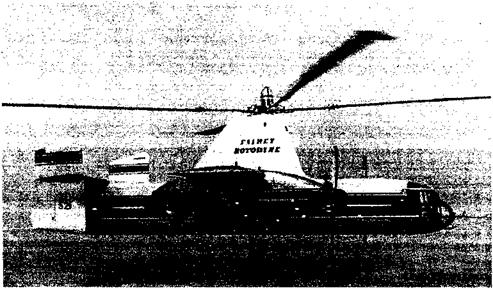
40 passengers – see Fig. 12.17. The program has been discussed by Hislop (1958) and

Renaissance of the Autogiro?

Figure 12.17 The Fairey Rotodyne was the world’s biggest gyroplane but it did not go into production. Source: Photo courtesy of Agusta-Westland.

McKenzie (1959). For takeoff and landing the rotor was driven by tip jets. The aircraft was a technical success and set a world speed record for a convertiplane in 1959 before the project was cancelled – see Boulet (1984) for a detailed discussion.

During the late 1950s and early 1960s, small commercial autogiros were developed in North America for the private aviation market by three companies: Umbaugh (later known as Air & Space), Avian, and McCulloch. While Umbaugh and McCulloch delivered over 100 machines, these had limited performance and the lack of sustained orders put the companies out of business. Single and two-seat autogiros were also built in Britain – see Wallis (1963). In the 1950s, Igor Bensen developed a homebuilt autogiro with an open airframe, based to some extent on the simplicity of the German Fa-330 “Kite” and Hafner “Rotachute.” A thriving amateur homebuilt autogiro market is still active today, many of these designs stemming from the Bensen designs. As of 2005, there were at least a dozen manufacturers in business catering to the homebuilt market – see the Popular Rotorcraft Association’s web site (2005), http://www. pra. org.

From a scientific perspective, there have been few recent studies of autogiros. However, work by Houston and colleagues (1998a, 1998b, 2000, 2001) has begun to reexamine the stability, control, and handling qualities of autogiros, mainly from a flight safety and certification standpoint. Advanced mathematical models of the autogiro were developed and validated by flight test measurements conducted on a specially instrumented two-seater autogiro. This work represents the first significant scientific interest in autogiros in over five decades and perhaps points the way forward toward improved future autogiro and gyroplane designs. While the autogiro led the development of the helicopter and there are clearly many similarities between the autogiro and the helicopter, it is perhaps ironic that fifty years hence the confidence levels in the design of a new autogiro are lower than for a new helicopter.

Recently, two companies in the United States have resurrected the idea of the autogiro or gyroplane and have begun to exploit its capabilities using modem technologies. These companies are Carter Aviation Technologies and Groen Bothers Aviation (GBA), Inc. The Carter test platform incorporates both a rotor and a large, relatively high aspect ratio fixed – wing. It is a hybrid aircraft using some of the underlying principles of the compound or convertiplane machines of the 1950s. While the rotor provides nearly all of the lift during takeoff and landing, the wing produces most of the lift at higher airspeeds, with the rotor almost completely offloaded and operating in its autorotational state. The high inertia rotor has a bearingless hub, with a tilting spindle to control the orientation of the rotor disk (much like in the original Cierva designs) and collective pitch to control rotor rpm. The machine is made almost entirely of composite materials and is powered by a lightweight propeller driven by a reciprocating engine. Conventional flight control surfaces (ailerons, elevator, and rudder) are used, again much as on the original Cierva Autogiro designs.

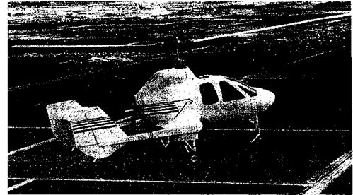
Groen Bothers Aviation (GBA) have developed a turboshaft powered gyroplane called the Hawk 4 (Fig. 12.18). The GBA machine provides all of the short takeoff and nearly vertical landing capabilities of the helicopter, with a demonstrated level flight speed of 148 mph (238 kph). Among other innovations, the two-bladed articulated rotor incorporates a cone-pitch coupling for improved rotor rpm stability. It uses a swashplate with collective and cyclic pitch, which gives the aircraft good maneuverability and also allows for short takeoffs. The all-metal blades use advanced airfoil sections that are designed specifically to meet the unique aerodynamic requirements of sustained autorotational flight. Unlike the Carter machine, there are no conventional flight control surfaces for roll or pitch, this all being achieved through rotor control, with rudder for directional (yaw) control.

Renaissance of the Autogiro?

Figure 12.18 Groen Bothers Aviation Hawk 4 is a modem turboshaft-powered gyroplane. Source: Photo courtesy of GBA.

Ground and Air Resonance

It has already been mentioned that, on the first autogiros, the in-plane Coriolis and drag forces on the blades were balanced by interconnected sets of wires between the blades. The blades were also restrained in flap by cables so that they could not “droop” when the rotor was stopped. Cierva found this interim solution rather unsatisfactory because the cables created high parasitic drag, reducing the overall performance of his Autogiros. Eventually, Cierva incorporated support stops instead of suspension cables and friction disks at the drag hinges to damp out any in-plane blade motion. He called these “cantilevered” blades, although the name is a misnomer because the blades were still articulated with mechanical hinges in the conventional sense.

While these ideas seemed to work fine on the lighter weight autogiros, a crop of new problems arose when they were applied to the bigger and heavier machines. These problems included lead-lag forces from Coriolis effects, high vibrations in the control system, large control forces, and a susceptibility to a destructive aeromechanical problem known as ground resonance – see Section 4.10 and Fig. 4.18. There were some limited technical efforts to understand the ground resonance problem on autogiros, but the “trial-and-error” approach meant that it was never satisfactorily resolved until much later when the same problems occurred on helicopters. In the 1930s, NACA made an attempt to study the ground resonance problem by mounting a camera high above the autogiro while the rotor was spun up on the ground. Another camera was mounted on the rotating hub to study the motion of a single blade. The NACA was to have a special interest in the phenomenon. Because of resonance on the mounting hardware, a specially instrumented autogiro that was being tested in the Langley full-scale wind tunnel was completely destroyed; see Gustafson (1971). In later years, helicopters were to suffer similar “resonance” problems, which were cured for the most part by the addition of mechanical dampers to the in-plane blade motion and changes to the undercarriage design. Coleman & Fiengold (1958) developed the first mathematical theory to predict and resolve the problem of ground resonance.

12.5 Helicopters Eclipse Autogiros

One practical limitation (and often the most popularized reason for the loss of interest in the autogiro) is that the autogiro cannot hover stationary in the air. Chamov (2003), however, explains that the reasons compounding its limitations may have been other than technical. While the efficient hovering flight capability of the helicopter is certainly a very desirable attribute, the autogiro still has the ability to take off vertically using the “jump” technique and can land almost vertically, especially into a wind. The autogiro is an efficient machine at low to moderate airspeeds and can outperform both the airplane and the helicopter under these conditions in terms of economics and also safety of flight. Unlike a helicopter, the autogiro has no “deadman’s curve” (see Section 5.6.2) and so can operate much more safely at lower altitudes and airspeeds. However, several early flying mishaps with the autogiro in the hands of inexperienced pilots led initially to a poor perception of the machine. Flight control was drastically improved by the use of “orientable” rotors. While efficient at low speeds, autogiros did not have the higher speed capability of airplanes designed in same time period, mainly because of its high parasitic drag. While much was done on later models of autogiros to increase streamlining and reduce rotor profile drag, especially by eliminating blade bracing wires, they were never to match the higher speed capabilities of airplanes. Furthermore, autogiros were mostly single or dual-seater aircraft, at a time when airplanes in the same weight and engine class could carry several passengers (and for a significantly lower cost). As alluded to earlier, scaling up the machine led to ground resonance and other problems, and these were not completely understood at the time.

While the autogiro was well-engineered, the high cyclic stresses imposed on rotating components meant that mechanical failures of the rotor system were not uncommon. Yet, it would be unfair to overemphasize any mechanical shortcomings of the autogiro at a time when all types of aircraft structural analysis was in its infancy. Autogiro designers worked steadily to improve the mechanical reliability and efficiency of the rotor design and the later designs were extremely robust and reliable. These technical accomplishments were to serve well the future designers of helicopters. By the early 1930s, helicopter pioneers, who for the most part were working independently of those developing the autogiro, suddenly realized that the autogiro had served to help work out all the problems of achieving proper control with helicopters. Thereafter, progress with the helicopter accelerated rapidly and interest in the autogiro dwindled.

Подпись:

Подпись: Jr'1'

Подпись: VUV11In December 1936, Juan de la Cierva was killed (at the age of only 41 years) in the crash of an airliner. This was a serious blow to the further development of the Autogiro. Shortly thereafter, the British government attempted to centralize rotating-wing research and engineering by trying to get the Cierva and Hafner companies to merge, but this initiative was unsuccessful. Raoul Hafner saw the autogiro only as an interim step toward the development of the helicopter; Juan de la Cierva did not and saw the autogiro я« th« nmfp. rrp. H яппгпягЬ

to rotor-borne flight. Nevertheless, both Cierva and Hafner saw the important future role of rotating-wing aircraft in both military and civil aviation. At the end of a lecture to the RAeS, Hafner (1938) stated: “We cannot afford to disregard the clear indications towards progress offered by the rotative wing. We can see the limitations with fixed wings – we must be aware of the limitation of fixed ideas; and if are to avoid flying and thinking in circles we must make the wing rotate.”

There were several other factors contributing to the loss of interest in the autogiro in the 1940s – see Chamov (2003). In the United States, military interest in the helicopter increased initially, and in 1938 the Congress passed the Dorsey Bill [see Smith (1985)],

which in part made possible the Rotating-Wing Aircraft Conference at The Franklin Institute in Philadelphia [see Institute of the Aeronautical Sciences (1938)]. This brought together most of the forward-thinking pioneers and technical specialists in the rotating-wing field, such as Hafner, Pitcairn, Kellett, and Sikorsky. Igor Sikorsky was already working toward the first flight of his VS-300 and in his paper [Sikorsky (1939)] at the subsequent Rotating – Wing Aircraft Conference in 1939, he was to extol the future potential of the helicopter. The imminent success of Sikorsky and his VS-300, funding from the Dorsey Bill and the technological advances made possible during wartime, eventually led to the successful development of a military helicopter in the United States.

Improving Performance: Jump and Towering Takeoffs

In a lecture given in Italy in 1929, Cierva first alluded to the idea of a giving his Autogiros a vertical takeoff capability. Initially introduced on a version of the Weir W-3 autogiro, the first advance made was that the rotor could be clutched to the engine through a lightweight transmission and spun up to a higher than normal rpm when the autogiro was on the ground. The second advance made was in the hub design to give it a blade pitch – change capability. While this hub went through many different changes, finally an ingenious kinematic blade pitch—lag coupling device was used to give a change in blade pitch between a low (zero thrust) setting and the normal flight pitch. This design was eventually to become the Cierva—Weir autodynamic rotor. Bennett (1961) explains how fifteen different hinge assemblies were tried before success was achieved.

The idea was that while the rotor rpm was over-sped on the ground up to a higher than normal flight rpm, the drag on the blades caused them to lag onto mechanical stops. Under this condition, the blade pitch was reduced to the low value by the coupling device. The rotor produced little lift in this condition. When the rotor was declutched from the engine, the blades snapped out of the stops and back to the original pitch. The resulting sudden surge of rotor lift caused the autogiro to “jump” into the air and climb rapidly off the ground (Fig. 12.16). While this jump takeoff capability comes about partially a result of the excess thrust produced by stored kinetic energy in the rotor system at the higher rpm, there are also aerodynamic benefits of a rapid change in blade pitch. This benefit gives a lag in the inflow development through the rotor and so a sudden thrust overshoot is produced — see Carpenter & Friedovich (1953) and discussion in Section 10.9. This excess or “dynamic”

Подпись: —30 ft
Improving Performance: Jump and Towering Takeoffs Подпись: (b) Towering takeoff
Improving Performance: Jump and Towering Takeoffs

Figure 12.16 The jump (a) and towering (b) takeoff capability gave the autogiro a capa­bility rivaling a helicopter.

thrust, however, decreases quickly (within a few rotor revolutions). Applying full engine power, as the machine climbs after the initial jump, accelerates it into forward flight, after which the rotor rpm decays to its lower flight value and the autogiro flies away normally.

However, there was always some loss of altitude with this jump takeoff technique (Fig. 12.16), the drag from the unpowered blades slows down the rotor rpm and con­tributes to a decrease in the initial dynamic thrust. Because the rotor also had a substantial backward tilt to aid in normal autorotation, there was a tendency for it to jump off slightly backwards. This increased the overall difficulty of the maneuver for the pilot. Good piloting technique, however, made the vertical jump takeoff technique consistently successful and the autogiro often rose quickly to more than 30 ft (10 m) into the air. The autodynamic rotor system was installed on a modified C-30 and was demonstrated successfully in 1935. By this time the Breguet-Dorand helicopter had made its first flights (see Chapter 1) and this significant advance in the performance of the autogiro received less attention than it might have done otherwise.

Raoul Hafner was to develop another type of jump takeoff system on his AR. III autogiro in 1935, which is described by Hafner (1938). This fixed hub, three-armed “spider” blade control system allowed the pitch of the blades to be continuously variable and to have both cyclic and collective capability. The spider sat atop the rotor and was actuated by a control rod supported on a spherical bearing inside the hollow rotor shaft. This design was technically superior to the Cierva-Weir “binary” blade pitch change system. To perform a takeoff with Hafner’s system, the pilot first over-sped the rotor with the blades in flat pitch while holding the machine firmly on the brakes (as with the Cierva jump takeoff system), and then rapidly applied pitch with a collective lever while simultaneously de-clutching the rotor, gunning the engine and applying forward cyclic. Hafner’s “spider” control system allowed the pilot to make continuous pitch control adjustments, allowing precise “towering” takeoffs with no loss in altitude as rotor rpm decayed (Fig. 12.16). Combined with a somewhat more exacting landing capability that was now possible with the “spider” hub, this version of the autogiro had a takeoff and landing flight capability that was to match future helicopters. The autogiro still could not hover, despite being able to make nearly vertical takeoffs and landings. However, Hafner’s spider blade pitch control system was soon to become the standard for early British-designed helicopters – see Hafner (1954, 1963).

The Americans too were also introducing the ideas of blade pitch control to autogiros to enhance its capabilities, with the Autogiro Company of America (its licensees were Pitcairn and Kellett) developing a jump takeoff system starting in 1933. Pitcairn had designed and patented many improvements into the Cierva rotor system [see Smith (1985)], and in 1931

Harold Pitcairn received the highly prized Collier Trophy for his technical contributions to aviation. See Pitcairn (1930) for a summary of activities, and Prewitt (1938) gives a technical discussion of the jump takeoff technique. The jump takeoff was also studied experimentally by Wheatley & Bioletti (1936) at NACA using model rotors and later by means of aerodynamic theory by Carpenter & Friedovich (1953). The mechanical systems used by the Americans were different to those of Cierva-Weir, but used the same principle of producing a jump takeoff by increasing rotor rpm followed by a sudden change in blade pitch. The American system was first tested on the PA-22 test bed and later on the enclosed cabin PA-36 with good success. Slowly, as the pilots gained experience, the jumps became higher and eventually Pitcairn pilots demonstrated an ability for the PA-36 to take off, translate into forward flight, and clear a 30-foot high obstacle without losing any altitude. Both Pitcairn and Kellett were later to compete for funding under the Dorsey-Logan Act of 1937 [see Smith (1985)] that specified a “rotary-wing military aircraft” capable of a vertical takeoff to clear a 50-foot obstacle. This goal was too unrealistic for the PA-36 to meet and it lost out on funding to LePage’s XR-1 side-by-side rotor helicopter (page 32), a machine that itself proved ultimately to be unsuccessful. Pitcairn’s PA-36 later made many successful jump takeoff demonstration flights to military and government officials, however, taking off and landing vertically and doing nearly everything a helicopter could do except hover. The jump takeoff worked, but it was never easy on the pilot or the aircraft.

Giving Better Control: Orientable Rotors

Peck (1934) conducted landing tests with the autogiro to help to quantify the poor roll control response that pilots found when autogiros with conventional airplane control surfaces flew at very low airspeed. Because the autogiro could be landed at almost zero ground speed, especially into a wind, the ineffectiveness of the ailerons under these conditions was a serious deficiency in the machine’s handling qualities and several crashes occurred. This gave the machine a less than desirable reputation amongst pilots and it was clear that the problem needed to be rectified by using some form of rotor control. While Cierva had initially investigated a disk tilting mechanism on the C-4 to provide roll control, the system was not viable at that time.

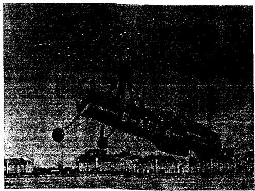
By 1931, Cierva had introduced the directly orientable rotor control. This “rocking head” design placed the rotor on a Universal joint or gimbal and essentially solved the control problem by allowing the entire rotor shaft to be tilted in any direction and so inclining the rotor lift force. This innovation allowed Cierva to dispense finally with the stub wings and the elevator: the rotor had enough control capability now for both roll and pitch. The rudder was retained for directional control. During 1932, the new device was tested on a C-19, which had no conventional airplane features except for a vertical tail and a rudder. The controls for the original tilting shaft design were shortly thereafter replaced by a “hanging stick” from the rotor hub to the cockpit, which gave the pilot both good control authority and also relatively light control forces in both roll and pitch. The device quickly became the new standard and was incorporated on all Cierva Autogiros manufactured after 1932, including the C-30 (Fig. 12.15), which became one of the most famous autogiros with nearly 200 being built in Britain, the United States, and France. However, the rotor vibrations were also transmitted through the control stick and this made the machines tiring to fly.

Giving Better Control: Orientable Rotors

Figure 12.15 A version of the Cierva C-30 showing for the first time the absence of conventional wings and ailerons and “hanging stick” design for “direct” rotor control.

NACA Research on Autogiros

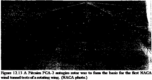
While the RAE in Britain had conducted experiments with autogiros, and had developed a theoretical basis for their analysis as early as 1926, it was not until the early 1930s that the extensive resources of the NACA were turned toward the science of rotating wings. Over the next ten or more years, the autogiro was to be tested extensively, with the work forming a solid foundation for later work on helicopters. In 1931, the NACA purchased a PCA-2 autogiro and this aircraft became the basis for extensive night and wind tunnel testing (see Fig. 12.13) for almost 8 years, until the helicopter appeared. Gustafson

(197І) gives a first hand summary of the early NACA technical work on both autogiros and helicopters, and Gessow (1948) gives a complete technical bibliography.

The first published NACA report on the autogiro was by Wheatley (1933a), which provided an authoritative baseline measurements on the performance of the PCA-2 autogiro. Measurements of rates of descents and glide angles were obtained (see Fig. 12.2), along with estimates of rotor lift-to-drag ratio. Separate tests of the rotor were also conducted in the wind-tunnel [see Fig. 12.13 and Wheatley (1934)] allowing quantification of the rotor

Подпись: Figure 12.13 A Pitcairn PCA-2 autogiro rotor was to form the basis for the first NACA wind tunnel tests of a rotating wing. (NACA photo.)

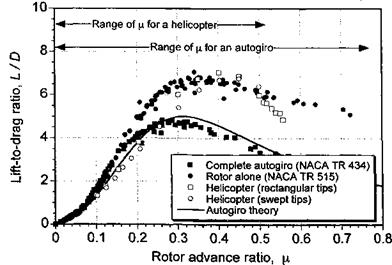
performance alone compared to the complete PCA-2 aircraft. As shown in Fig. 12.14, the aerodynamic efficiency of the autogiro was relatively poor compared to most airplanes, with a maximum L/D ratio of only about 4.5. The differences between the rotor alone and the complete aircraft reflects the high parasitic drag of the airframe. However, to put the results in perspective, the performance of the rotor alone, which had a maximum L/D ratio of about 7, is comparable to that of a modem helicopter rotor. Notice that for higher advance ratios (or tip speed ratio) the helicopter rotor L/D ratio drops off markedly, in part because of retreating blade stall and advancing blade compressibility effects, whereas because the

NACA Research on Autogiros

Figure 12.14 Lift-to-drag ratio in autorotation for complete autogiro (PCA-2) versus the rotor alone. The lift-to-drag ratio of a rotor in autorotation is comparable to that of a modem helicopter rotor. Data source: Wheatley (1933a) and Wheatley & Hood (1934).

autogiro rotor has a relatively low rpm and low disk loading it retains its L/D ratio to as high as /л = 0.7 (although not necessarily to a higher airspeed).

Wheatley (1933b) studied the load sharing between the rotor and the wing and also examined the maneuver characteristics of the autogiro. One of the most remarkable findings in this work was a sustained maximum maneuver load factor of 4.3, which is high for any kind of rotorcraft and rarely obtained even on modern combat helicopters during transient maneuvers – see Section 5.9. The main reason for this large value was the relatively low blade loading and low mean lift coefficients of the autogiro rotor, which lead to good stall margins. The role of the wing was also important in off-loading the rotor at higher airspeeds and during maneuvers. Flight tests with the PCA-2 demonstrated forward speeds of 140 mph, with an advance ratio in excess of p = 0.70. This is a very high advance ratio for a rotor, but is possible on an autogiro if the rotor is offloaded by a wing.

The earliest theoretical studies of the autogiro at NACA resulted in one of the first thorough aerodynamic analyses of the rotor – see Wheatley (1934b) & Bioletti (1935). Later, a now classic report by Bailey (1941) extended the earlier work of Glauert (1926, 1928) and Lock (1928) and included the treatment of blade twist, reverse flow, nonuniform inflow, and tip-loss effects on the aerodynamics of the rotor. The predictions were shown to be in good agreement with both flight and wind tunnel measurements. The NACA worked extensively on several other technical problems (both from an experimental and a theoretical perspective) that w ere to occur during the maturation process of the autogiro. This included work on rotor dynamics, vibration, airfoil sections, jump takeoffs, and ground resonance – see Gustafson (1971).

Airfoils for Autogiros

Cierva was well aware of the importance of airfoil shape in improving the per­formance of his autogiros [see Cierva (1930c) and Cierva & Rose (1931)]. He wrote in reference to the twisting moment produced on autogiro blades by the use of a cambered airfoil versus a symmetric airfoil: “It [the Gottingen-429] is a reasonably efficient airfoil, although others give greater lift and a great many different curves are used for designing [fixed-wing] airplanes. But, the important advantage of this particular type is that its center cf lift or pressure is approximately the same at all angles which it may assume in flight. This is not true of other types of airfoil, so that center of pressure travel is a factor to be reckoned with in using them.” In essence, Cierva is referring here to the connection between aerodynamic performance (better maximum lift coefficient and improved lift-to-drag ratios) through the use of camber and the corresponding increase in pitching moments caused by that camber – see Section 7.7.3. Compressibility issues on the advancing blade can be an issue for an autogiro, although somewhat less so than for a helicopter because the autogiro operates at lower mean lift coefficients, but there is still a need to use airfoils with good aerodynamic characteristics at high subsonic Mach numbers.

Cierva had many airfoil sections to choose from, but the aerodynamic characteristics of most were not well documented. On the C-4, Cierva used the Eiffel 106 airfoil section, later

Airfoils for Autogiros

Figure 12.12 Two types of airfoils that were used on the Cierva Autogiros: (a) the sym­metric Gottingen-429, (b) the reflexed cambered RAF-34.

switching to the Gottingen-429 airfoil. Some years later, Cierva was again to reconsider the choice of the airfoil section for his Autogiros, but, limiting his study to ten candidate airfoil sections, he decided to replace the symmetric Gottingen-429 airfoil, which had “abrupt stalling” characteristics with the reflexed-cambered RAF-34 airfoil of 17% thickness-to – chord ratio (see Fig. 12.12). The new blades were first tested on the C-19 Mk-IV, which became one of the most successful Cierva Autogiro designs. On the C-30 Autogiro, Cierva switched the airfoil again, this time to the cambered Gottingen-606 airfoil. In some flight conditions, mainly at high airspeeds, the higher pitching moments resulted in the blades twisting elastically and so this produced control problems. These aeroelastic effects arose because of the generally low torsional stiffness of early wood and fabric covered rotor blades. A crash of a C-30 Autogiro was tied to the use of this cambered airfoil sec­tion – see Beavan & Lock (1939). The NACA had also noticed such aeroelastic problems and had analyzed the effects of blade twisting – see Wheatley (1937a, b). On the Kellett YG-1 (which also used the Gottingen-606 airfoil) but with an upward deflected trailing edge tab, the NACA eventually replaced the blades with a reflexed airfoil based on the NACA 230 series. Yet, these airfoils were not successful and were found to have relatively poor characteristics at high lift and at high speeds – see Bailey & Gustafson (1939) and Gustafson (1971).