Autorotation has been defined in Chapter 2 as a self-sustained rotation of the rotor without the application of any shaft torque (i. e., Q = 0 at the rotor shaft). In autorotation the energy to drive the rotor comes from the relative airstream, which is directed upward through the rotor. To see why, the problem can first be approached from momentum theory applied to a powered rotor in vertical descent, a method introduced in Chapter 2. In vertical climb or descent at a given rotor rpm, the torque ratio (the torque, <2, that is required to produce a given rotor thrust relative to the torque required for a shaft driven rotor to hover,
Qh) is
Q QQ F VC’
Qh QQh Fh Vh Vh
where Vc is the climb velocity, u, is the induced velocity through the rotor and Vh is the induced velocity in shaft-powered hovering flight (generally this is always used as a reference). The two terms on the right-hand side of this equation represent the torque associated with any change the potential energy of the rotor and the aerodynamic (induced) losses, respectively. The solution for Vi/vh can be calculated using momentum theory as a basis (see Section 2.13.4), although vertical autorotation actually occurs in a condition where momentum theory offers no exact solution for the induced velocity – see Fig. 2.20.
In practice, there are also profile losses to overcome. Therefore, in an actual autorotational condition then
 Q — — (Ус + vi) + Qo — 0.
where T is the rotor thrust and Qo represents the torque to overcome blade profile losses.
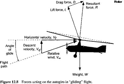
Clearly Vc must be negative to produce autorotation (i. e., the aircraft must give up potential energy). When in a stable “gliding” autorotation with a constant airspeed and constant rotor rpm, there is an energy balance where the decrease in potential energy of the rotor, —TVC, just balances the sum of the induced and the profile losses of the rotor at that rpm. The ideas of an energy balance in autorotation were first explored by Cierva [see Cierva (1926)]. Using Eq. 12.2, this condition is achieved when
 Ye. —
Ye. —
vh vh T vh
The second term on the right-hand side of Eq. 12.3 depends on the profile drag of the rotor blades (i. e., on the rotor solidity and the average drag coefficients of the airfoil sections used on the blades). However, compared to the induced part, which is defined by the curve that has been shown in Fig. 2.20, the extra rate of descent required to overcome profile losses is small. In practice, in a vertical autorotation the nondimensional rate of descent, Vc/vh, is found to be between —1.8 and —1.9. For the larger value, this is equivalent to a vertical rate of descent


 1.9 [f [T
—j=J — = 27.55J — in units of ft/s V2pV A V A at sea level atmospheric conditions. Equation 12.4 shows that the autorotational descent rate is proportional to the square-root of the rotor disk loading, T/ A(= WJ A). Cierva’s early Autogiros all had disk loadings of about 2 lb/ft2 (96 N/m2), which is also typical of modem autogiro designs. This would give a vertical autorotative rate of descent at sea level of about 39 ft/s (12 m/s) or 2,340 ft/min (713 m/min).
Unlike the helicopter, the autogiro’s rotor must always operate in the autorotative working state, where the power to turn the rotor comes from a relative flow that is directed upward through the rotor disk. The low disk loading (T j A) of an autogiro’s rotor (and, therefore, the low induced velocity through the rotor disk) means that only a small upward flow normal to the rotor TPP is necessary for the rotor to enter into autorotation compared to a helicopter. While the autogiro is not a direct-lift machine (nor was it designed to be) and cannot hover, it requires only minimal forward airspeed to maintain flight. Therefore, in straight-and-level forward flight, the rotor disk needs to operate only with a slight positive AoA (backward tilt). As long as the machine keeps moving forward though the air, the rotor will continue to autorotate and produce lift. Reducing engine power will cause the machine to descend slowly and increasing power will cause it to climb. The stoppage of the engine is never really a problem on an autogiro because the rotor is always in the autorotative state and so the machine will descend safely to the ground. The rotor can, however, exit the autorotative state as a result of poor piloting technique.
Measurements documenting the performance of autogiros are rare and go back to the 1930s. Detailed in-flight measurements were conducted by the RAE using a Cierva C-30 [see Hufton et al. (1939)] and by NACA using a Pitcairn PCA-2 [see Wheatley (1933a)]. See also Harris (1992) for these data. The autorotational rate of descent, Vd, for both machines is plotted in Fig. 12.2 as a function of forward speed, V/, both parameters being
CsJ
|
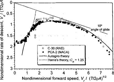
Figure 12.2 Nondimensional rate of descent in autorotational “gliding” flight versus nondimensional forward speed. Data source: Wheatley (1933a) and Hufton et al. (1939).
|
nondimensionalized by V/-T’/2pA, which essentially removes the effects of disk loading from the results. It is apparent that the measured vertical rate of descent occurs at about Vd/VT/2pA = 1.9, which is in good agreement with the result given in Eq. 12.4 – see also Section 2.13.7. As previously mentioned, there is no exact theory describing the rotor aerodynamics in autorotation, even if the rotor has forward (translational) speed, but as airspeed builds momentum theory gives a better and better approximation to the predicted rate of descent in autorotation – see Section 12.9. The measurements in Fig. 12.2 clearly show a rapid decrease in the autorotational rate of descent as forward speed builds. A minimum rate of descent is reached at about Vf/^/T/2pA = 2 (in practice this corresponds to about 35-40 kts or 65 km/h to 74 km/h), which is the point where aerodynamic losses at the rotor are a minimum, and the rate of descent slowly increases again thereafter.
Also of interest is the autorotational rate of descent versus the rotor disk angle of attack. While the forgoing measurements were performed in descending “gliding” flight, autorotation is also possible in level flight with propulsion from a propeller to drive the autogiro forward. All that is required is that the rotor disk be held at a sufficient AoA such that the component of the relative wind upwards through the disk causes the rotor to autorotate. In the words of Juan de la Cierva himself [see Cierva & Rose (1931)] “It makes no difference at what angle the Autogiro is climbing or flying. The blades are always gliding toward a point a little below the focus of forward flight. It is impossible, therefore, for autorotation to stop while the machine is going anywhere.” This bold statement, however, excludes the possibility of bad piloting technique.
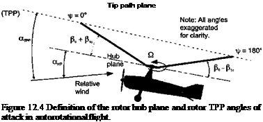
The results in Fig. 12.3 show the measured hub plane AoA as a function of the resultant nondimensional velocity of the aircraft. In a pure vertical descent it is apparent that the TPP and hub plane angles of attack are both essentially 90° (the resultant wind in this case is perpendicular to the disk). As forward speed builds, the hub plane needs to make a progressively smaller angle to the relative wind to enable autorotation, until at higher speeds the rotor must be held only at a shallow angle to produce enough lift in the autorotational
state. The rotor TPP angle is also inclined back but is not equal to the hub plane AoA because of blade flapping (see Fig. 12.4 and also discussion in Section 4.9). The natural tendency

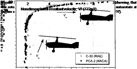 |
to produce longitudinal napping (i. e., a pc component) component of velocity upward through the disk, which means the hub plane angle is always relatively small in forward flight. The TPP has a positive AoA much like a wing under these conditions – see page 94 and Glauert (1926, 1928).
Cierva juggled with the parameters affecting the magnitude and direction of the aerodynamic forces acting on the rotating blades and concluded that there could be many different combinations of rotor operating conditions where the net torque on the rotor shaft could be zero. Consider the flow environment encountered at a blade element on the rotor during autorotation, as shown in Fig. 12.5 where the relative velocity is directed upward toward the rotor. For autorotational equilibrium at that section the inflow angle, ф, must be inclined
Thrust force


 NOTE: Angles exagerated for clarity

 Net I Resultant velocity
upflow
In autorotation, flow is upward through the rotor Figure 12.5 Detail of the flow at a blade element in autorotational flight.
forward such that there is no net in-plane sectional force and, therefore, no contribution to rotor torque; that is, for force equilibrium at that section

 dQ = (D – (f>L)y dy = 0, or that in coefficient form, we have Cd – фС1 = 0.
However, this is an equilibrium condition that cannot exist over all parts of the blade and only one radial station on the blade can actually be in proper autorotational equilibrium. In general, it has been shown previously by means of Fig. 5.24 that some portions on the rotor will absorb power from the relative airstream and some portions will consume power, such that the net torque at the rotor shaft is zero (i. e., fdQ = 0). For autorotational equilibrium the induced angles of attack over the inboard stations of the blade are relatively high and near the tip the values of ф are relatively low. We find that at the inboard part of the blade the net AoA results in a forward inclination of the sectional lift vector, providing a propulsive component greater than the profile drag and creating an accelerating torque – see Fig. 12.5. This blade element can be said to absorb energy from the relative airstream. Toward the tip of the blade where ф is lower and these sections of the blades consume energy because the propulsive component as a result of the forward inclination of the lift vector is insufficient to overcome the profile drag there (i. e., a net decelerating torque is produced).
As Cierva understood, in the fully established autorotational state at a given blade collective pitch angle the rotor rpm will adjust itself until a zero torque equilibrium is obtained. Assuming unstalled blades, then this is a stable equilibrium because it can be deduced from Fig. 5.24 that if Q, increases, ф will decrease and the region of accelerating torque will decrease inboard and this tends to decrease rotor rpm. Conversely, if the rotor rpm decreases, then ф will increase and the region of accelerating torque will grow outward. Therefore, when fully established in the autorotative state, the rotor naturally seeks to find its own equilibrium rpm in response to any changing flight conditions. This is an inherent characteristic of the rotor that gives the autogiro very safe flight characteristics.
However, in the autorotational state the blade pitch must always be at a low value and the disk AoA must be positive to ensure that the inboard blade sections never reach high enough angles of attack to stall. Stall may occur if the rotor rpm decays below an acceptable threshold, such as when the disk AoA becomes negative, or a reduced or negative load factor is produced. These are flight conditions to be avoided. If stall does inadvertently occur, then the outward propagation of stall from the blade root region will cause rotor rpm to decrease quickly because of the associated high profile drag.










 Net I Resultant velocity
![Autogiros and Gyroplanes[44] Подпись: Drag from rotor](/img/3130/image1920.png)
![Autogiros and Gyroplanes[44] Autogiros and Gyroplanes[44]](/img/3130/image1921.jpg)
![Autogiros and Gyroplanes[44] Подпись: Propulsion from rotor](/img/3130/image1923.png)
![Autogiros and Gyroplanes[44] Autogiros and Gyroplanes[44]](/img/3130/image1925.jpg)