Category Principles of Helicopter Aerodynamics Second Edition

Effects of the Fuselage on Rotor Performance

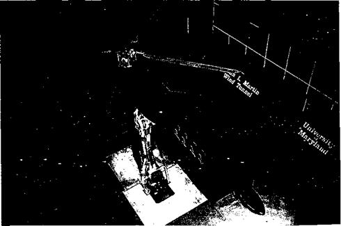
Betzina & Shinoda (1982), Smith & Betzina (1986), Brand et al. (1986, 1989, 1990), and Leishman & Bi (1990a, 1990b, 1994a, b) have conducted wind tunnel tests to investigate aerodynamic interactions using subscale rotors and relatively simple bodies of revolution. Most studies have concluded that the rotor performance was to some extent affected by the presence of the body, but that the aerodynamic characteristics of the body were highly modified by the presence of the rotor and its wake. Such tests on fairly generic fuselage configurations (easy to define geometrically) can help the analyst to better isolate the specific aerodynamic phenomena that allow for fundamental understanding. For exam­ple, Fig. 11.2 shows an example of a subscale rotor with a geometrically simplified airframe being tested in a wind tunnel, in this case with a body of revolution for the fuselage and a simple T-tail empennage. There was no tail rotor in this case. These types of geometri­cally simplified setups gives the analyst the ability to carefully study the flow physics of specific aerodynamic phenomena with greater confidence than could be done with more representative helicopter airframe configurations. The results also give the analyst the best opportunity to precisely define the geometry of the problem to validate computational flow studies. This will help to improve confidence levels in comprehensive flow models that predict the detailed viscous flows about actual helicopter airframes.

Effects of the Fuselage on Rotor Performance

Figure 11.2 A subscale helicopter rotor with a geometrically simplified airframe (body and T-tail) geometry being tested in a wind tunnel.

Effects of the Fuselage on Rotor Performance

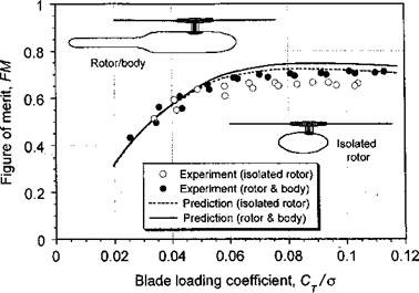
Figure 11.3 The figure of merit of the rotor will be affected by the presence of an airframe.

Data source: Bagai & Leishman (1992). Analysis: Crouse & Leishman (1992).

Perhaps surprisingly, it has been found that the introduction of a body into the flow field near the rotor can give a beneficial reduction in rotor power requirements for a given thrust, but only when operating in hover and in forward flight at low advance ratios. For example, Fig. 11.3 shows the figure of merit of a rotor for a range of thrust coefficients in hover. Results are shown with and without a body.[43] As the rotor thrust increases, the presence of the body produces an increase in the rotor figure of merit; the increase shown (about 5% at Ст /cr = 0.10) is clearly significant. There is also a download on the airframe induced by the rotor (which governs the net vertical force on the rotor-airframe combination), an effect that is discussed in Section 11.2.2. The most obvious reason for the change in rotor performance is the body’s effect on the induced inflow through the rotor disk; the body reduces the inflow through the disk in the regions directly above itself and changes the effective angles of attack on the blade elements. This, in turn, affects the lift distribution over the blades, which becomes more heavily biased toward stations further inboard for a given rotor thrust. While the blade airloads are also unsteady, the effect of the body has the same effect as increasing the average value of the effective blade twist (in a more ideal way). It is apparent then that this particular interaction is actually beneficial and, in this case at least, gives the rotor increased hovering efficiency.

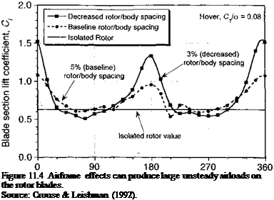
To expound on this point, Fig. 11.4 shows a plot of the computed time history of the lift coefficient at an inboard section of the blade in the region directly above the body surface. Clearly the mean value of lift is increased by the body, which is a direct result of the decrease in induced inflow at this blade station by the influence of the body. Furthermore, notice that, compared to values for the isolated rotor, the lift is now time-varying, with a 2/rev unsteady component. Because, in this case, a four-bladed rotor was used, the net effect of this interaction will be an 8/rev aerodynamic excitation at the rotor. As the blades pass over the rear of the fuselage (at jr = 0°) notice that there is a stronger effect than when the blades pass over the front of the fuselage (at 1fr = 180°). This is expected based on the slightly larger clearances between the blades and the nose of the body. The results also
Подпись: Figure 11.4 Airframe effects can produce large unsteady airloads on the rotor blades. Source: Crouse & Leishman (1992).

Blade azimuth, – deg.

show that decreasing the spacing between the rotor and the body amplifies the unsteady lift. (There is also a reciprocal effect on the airframe airloads – see Fig. 11.15.) This is an example of why decreasing the rotor-airframe spacing on a helicopter generally increases vibratory airloads and why, if the spacing becomes too small, vibration problems will result that are difficult to solve (especially for helicopters using rotors with higher disk loadings) unless rotor-airframe spacing is ultimately increased again.

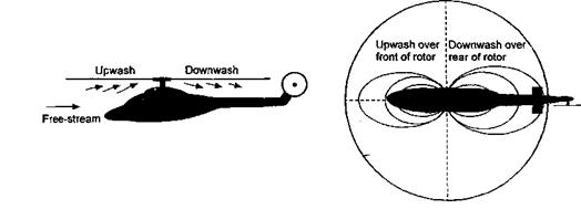
Similar types of interactions also occur in forward flight. However, the relative position of the rotor wake to the body is important here, and the wake position becomes a function of rotor thrust and advance ratio (see Section 10.4.1). There are also self-induced effects on the rotor wake that are produced by wake distortions induced by the airframe surfaces. As forward speed increases, the rotor wake quickly skews behind the rotor disk and the wake interactions between the rotor and the body become somewhat weaker. Yet, there are also other complicating aerodynamic factors that occur in forward flight. One is that the fuselage produces flow field perturbations in the rotor plane as forward speed builds – see Fig. 11.5. This effect, however, becomes significant only at relatively high forward speeds

Effects of the Fuselage on Rotor Performance

Figure 11.5 Fuselage effects in forward flight will cause an upwash perturbation over the front of the rotor and a downwash over the rear of the disk.

Cp/o Cp/o

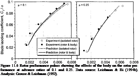
Подпись: Figure 11.6 Rotor performance polars showing the effects of the body on the rotor performance at advance ratios of 0.1 and 0.25. Data source: Leishman & Bi (1994b). Analysis: Crouse & Leishman (1992).

(say for jJL > 0.3) but it can make a difference to the blade airloads and rotor performance. However, the unsteady effects from blade passage and induced pressures associated with the convection of the discrete wake vortices (see Section 11.2.3) remain important at all advance ratios, and these effects may even increase in intensity at higher forward flight sneeds as rotor thrust increases to meet Drooulsive reauirements.

і 1 1

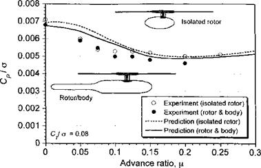
Figure 11.6 shows an example of the rotor performance polars in forward flight at advance ratios of fi = 0.10 and /z = 0.25. At the relatively low advance ratio of /z = 0.10 there are notable differences between the performance of the rotor with and without the body present. As expected, the changes become more apparent at higher rotor thrust values as the interactions between the rotor and the airframe strengthen. As the advance ratio is increased, however, the effects of the body on the rotor are progressively reduced. At an advance ratio of (i — 0.25 there are almost no differences between the rotor-body case and the isolated rotor. This is because the wake is now much further away from the fuselage, and there is a weaker body-induced wake distortion – see Figs. 11.7 and 10.10. At this condition the rotor and the body each behave more like they would in isolation, although not completely. At both advance ratios, the analysis [Crouse & Leishman (1992)] predicts the changes in the rotor power to within the bounds of experimental measurement uncertainty. See Section 11.2.3 for modeling requirements and the types of approaches.

(a) Low-speed forward flight (b) High-speed forward flight

Effects of the Fuselage on Rotor Performance

Figure 11.7 As forward speed is increased the main rotor wake is skewed behind the rotor, (a) Low-speed flight, (b) High-speed flight.

Effects of the Fuselage on Rotor Performance

Figure 11.8 The effect of increasing advance ratio will initially be to decrease the signif­icance of rotor-airframe interactional effects on rotor performance. Data source: Leishman & Bi (1994b). Analysis: Crouse & Leishman (1992).

The net rotor power required for rotor operation at the same nominal thrust over a range of advance ratios is shown in Fig. 11.8. As expected, the greatest differences between the isolated rotor and the rotor-body combination are in low-speed flight; as advance ratio increases the differences decrease. It might be expected that at very high advance ratios (>0.4) some degree of interaction returns because the fuselage will produce larger flow disturbances in the rotor plane, as suggested by Fig. 11.5. This effect has been studied by Wilby et al. (1979), Ryan et al. (1988), Dehondt & Toulmay (1989), and Rand & Gessow (1989) using a potential flow methodology. This seems to give a good first order approximation to the perturbations in blade angles of attack caused by the fuselage. The interactional effects, however, are confined mostly to the regions near the rotor hub, which do not contribute as much to rotor lifting and propulsive capability. The effects, therefore, show up more in blade airloads and aeroelastic response and less in contributing to overall rotor performance.

Rotor-Fuselage Interactions

The effects of the rotor wake on the fuselage airloads are a senous cause for conce* n on all modem helicopters. This is especially the case in hovering and low-speed forward flight where the rotor wake will envelop a good part of the fuselage (and perhaps also the empennage). While there have been earlier studies of this problem, the first systematic wind tunnel study into rotor-airframe problems was conducted by Sheridan (1978) and Sheridan & Smith (1979). In more recent years, a significant amount of detailed experimental and theoretical research has been accomplished to provide a more thorough understanding of the aerodynamic interactions between rotors and (nominally) nonlifting bodies of relatively simple geometric shape, such as bodies of revolution [e. g., Komerath et al. (1985), Smith & Betzina (1986), and Leishman & Bi (1990b)], although more complex body shapes and scaled helicopter airframes have also been studied [e. g., Freeman & Wilson (1980), Trept (1984), Berry (1988), and Le Pape et al. (2004)]. More recent efforts to study rotor – airframe interactions have been specifically aimed at gaining a more complete understanding of the underlying fluid mechanics. There has been particular experimental and theoretical emphasis on the unsteady airloads caused by the interaction of the rotor blade tip vortices

TTr;+U Ашаіллл пп^пллг лигиЛл __________________ і_____ і:___ j___________

w tun Lilt* luatiagg йипак, са. yy nut; vuiic^A iiiijJillg^UlCUl jJUCUUlUCUcl clIC lUCiUUCU UU ШС

airframe, the intense unsteady airloads produced can contribute significantly to overall helicopter vibration levels. Other unsteady airloads are produced each time a blade passes over the fuselage, which creates an abrupt pressure pulse over a substantial part of the airframe. These pressure pulses depend on rotor blade loading and occur in phase with each blade passage; they can lead to low-frequency airframe and rotor vibrations that have considerable intensity. Several prototype helicopters have been designed with minimal rotor-fuselage spacing and have encountered insurmountable vibration problems that could only be solved (ultimately) by increasing the rotor-fuselage spacing. Currently, it is not clear if such vibration problems can be solved by other means. An unfortunate byproduct of increased spacing, however, is an increase in parasitic drag.

A reciprocal effect of the fuselage may occur on the rotor, where the blade airloads and rotor performance are changed – see Wilby et al. (1979), Rand (1989), and Crouse & Leishman (1992). The presence of the fuselage distorts the inflow through the rotor disk and this affects the blade airloads, the rotor performance, and the blade pitch control angles required for trimmed flight. Wilby et al. (1979) have shown that in forward flight the fuselage-induced upwash velocities can provide a perturbation to the aerodynamic angles of attack over the front of the rotor disk, which can significantly affect the blade airloads and net rotor response. Smith (1987) has shown that the wake distortion associated with fuselage interactions can generate enhanced rotor wake interactions that may trigger a torsional aeroelastic response of the rotor and could lead to a premature retreating-blade stall. Such effects are recognized based on flight testing experience, but are not well understood or predictable because they are sensitive to the flight conditions and to the ability to predict the detailed aerodynamics at the rotor. This also makes the underlying aerodynamic issues hard to study in more controlled wind tunnel experiments because not all flight conditions can be replicated. The effects and consequences of fuselage-on-rotor aerodynamics will require relatively sophisticated and fully coupled rotor wake and airframe models if their effects are to be predicted accurately. Other authors, including Johnson & Yamauchi (1984), have also emphasized the importance of and difficulties attributed to rotor-airframe aerodynamic interactions when predicting the airloads and aeroelastic response of rotors.

Rotor-Airframe Interactional Aerodynamics

Interaction phenomena remain for the foreseeable future beyond the possibilities of present viscous flow codes.

S. R. Ahmed (1990)

11.1 Introduction

Chapter 10 has described the physics of the helicopter rotor wake and its inherent 3-D complexity. This chapter describes the fundamental nature of the aerodynamic interac­tions that occur as the rotor wake influences the flow about the airframe. Despite the partic­ular aerodynamic issues of the subcomponents of the helicopter (i. e., the rotor, fuselage, tail rotor), all of these subcomponents exhibit fairly well-understood aerodynamic characteris­tics when operated in isolation, at least from an engineering perspective.[42] The performance of the isolated components is also fairly predictable, despite the fact that semi-empirical methods often need to be used. However, when these subcomponents are integrated as a system, their aerodynamics change because of interactions and so their performance char­acteristics will be different from their isolated behavior. In many cases, the aerodynamic interactions are benign, but in some flight conditions the interactions may be deleterious. This can result in behavior that may detract from the overall performance characteristics of the helicopter (such as producing downloads, airframe moments, or vibrations). The primary interactional effects are produced on the fuselage and empennage of the helicopter. Yet, the aerodynamics and performance of the tail rotor are also subjected to interactional aerodynamic effects. Tail rotor operation is strongly influenced by the presence of the main rotor wake, the downstream turbulence from the main rotor hub, and also from the influence of the vertical and horizontal tails. Because the helicopter as a system must function properly and predictably throughout its operational flight envelope (including hover, forward flight, climbing flight, and during many other flight maneuvers), an understanding of component – interaction aerodynamics is essential to the successful design of the modem helicopter.

The various aerodynamic interactional effects between airframe and rotor components are summarized in Fig. 11.1, which is adapted from the seminal work of Sheridan & Smith (1979). This work has led to general design guidelines for minimizing the numerous types of adverse interactional aerodynamic problems found on helicopters. There have been many subsequent studies to understand the physics responsible for the various problems by means of wind tunnel and flight tests. Yet, many features of flow interactions are still not well understood from a fundamental perspective, nor are they predictable using mathemat­ical models. This is reflected by the redesign of many prototype helicopters after first flight because they have shown undesirable flight characteristics, which in many cases have their origin in adverse aerodynamic interactions. One common problem is with the placement

Rotor-Airframe Interactional Aerodynamics

Blades

Rotor

>

<

A >

< >

<

Rotor-Airframe Interactional AerodynamicsПодпись: Stub wing Sponson / < У < > f > f > f Подпись: EmpennageПодпись: Fin * A

Ground

Figure 11.1 Schematic showing the various aerodynamic interactions that can exist be­tween rotor and airframe components. Adapted from Sheridan & Smith (1979).

and sizing of the horizontal tail relative to the rotor, and nearly every new helicopter in recent years has experienced some unforeseen problem with the empennage design. The typically long tail boom found on the helicopter and the placement of the tail surfaces well aft on the fuselage or tail boom mean that changes in the position of the main rotor and rotor wake can produce airloads on the tail that may have a significant impact on fuselage pitching moments. The sensitivity of these effects to flight conditions can have a large impact on the overall flight characteristics and handling qualities of a helicopter. In essence, this is the fundamental reason for gaining a better understanding of rotor-airframe interactions through basic research; an improved understanding and predictive capability will ultimately allow any adverse effects to be minimized at the design stage rather than after expensive flight testing.

As discussed in Chapter 6, the fuselage is the largest airframe component and a lot of attention has been placed on gaining an improved understanding of the effects of the rotor on the fuselage aerodynamics. The presence of the fuselage also distorts the inflow through the rotor disk and this affects the blade airloads and rotor performance. These effects, however, are very difficult to predict because the rotor aerodynamics must be modeled using relatively sophisticated forms of unsteady aerodynamics (see Chapter 8) and rotor wake analyses such as free-vortex methods (see Chapter 10) or other advanced wake methods (see Chapter 14). In the quest for more compact, lighter, faster, and more maneuverable helicopters, current design trends are moving toward the use of higher ro­tor disk loadings and smaller rotor-fuselage spacing. In addition, cutting down on rotor hub drag in forward flight (see Section 5.5.10) is one strong motivation to use reduced rotor-fuselage spacing. Furthermore, the need to deploy military helicopters inside exist­ing cargo aircraft without significant disassembly has demanded an overall more compact helicopter design. However, the stronger blade tip vortices (see Section 10.6) and higher downwash velocities intrinsically associated with smaller rotors operated at higher disk loadings mean that stronger aerodynamic interactions between the rotor and the fuselage

may be produced. The aerodynamics of the tail rotor is also affected by the main rotor wake and in some cases, the effects of these interactions can involve the production of significant unsteady airloads on the blades coupled with losses of tail rotor anti-torque efficiency or control effectiveness, as well as high noise production. Therefore, for the helicopter to be an efficient machine the fuselage must be carefully integrated aerodynamically with the main rotor, as well as with the empennage and the tail rotor.

Wake Developments in Maneuvering Flight

The problem of modeling helicopter rotor wakes under maneuvering flight condi­tions is not a new one [see Sadler (1972)]. The effects on the inflow resulting from rotor wake distortion during maneuvering flight has been suggested as one of the contributing sources of the so-called “off-axis” response problem of helicopters. This problem manifests as a pitch response resulting from a lateral cyclic input and/or a roll response resulting from a longitudinal cyclic input in pitch – see, for example, Tischler et al. (1994), Mansur & Tischler (1996), and Keller & Curtiss (1996). A maneuver, whether it be pitching or rolling or a combination of such, clearly provides an additional potential source of aerodynamic forcing into the rotor problem and would be expected to produce some further distortion effects into the rotor wake compared to that obtained under straight-and-level flight condi­tions. The exact understanding of how this effect occurs, however, is the subject of ongoing research. Clearly, if a modified wake topology is produced by the maneuver, this will change the induced inflow, which in turn will affect the blade loads, the rotor flapping response, and, therefore, the control inputs required to execute the maneuver. The problem is how to calculate such highly coupled effects, which requires a fully integrated aerodynamic, rotor dynamic, and flight mechanics simulation. While comprehensive flight mechanics models are available, the fidelity of the aerodynamic models that can be viably included so far has been limited because of their extremely high computational costs.

There have been several recent developments of rotor wake models directed toward the understanding and prediction of the off-axis response problem. Basically, this is a nonin- tuitive flapping response of the rotor resulting from the maneuver. For example, for a roll to the right (to starboard) then conventional theory (i. e., linearized, blade element theory) would say that the change in velocity across the disk from a roll rate would increase the AoA and lift of the blades on the advancing side of the disk and decrease the lift on the retreating side. This would be expected to cause a backward flapping of the rotor disk, that is, a —fic flapping motion. Instead, in practice the rotor disk is found to flap forward and this is one consequence of the off-axis response problem. Using a relatively simple
prescribed wake with assumed (prescribed) maneuver induced distortion effects, Rosen & Isser (1995), Arnold etal. (1995), Keller & Curtiss (1996), and Barocela et al. (1997) showed improved correlations of the off-axis rotor response when compared to flight test data. Rosen & Isser’s approach, like most vortex wake models that may have the fidelity necessary to predict maneuver induced wake distortion effects, is computationally expensive to include in flight mechanics simulations. The techniques of Keller & Curtiss (1996) are based on an extended momentum theory approach to represent the effects of the rotor wake, and is in a form easily included in such simulations. Both these techniques, however, assume that the maneuver-effects on wake distortion can be preassumed. This is done by correlating

tbp r^cnltc x/itb fiiaht fpct Ante* япН inpliiHintr foptnre infn tbp чх/яЪ-а гппНрі tViat пглНпрр tbp

U1V Д WLFM1I. LJ ТТДИІ I. VU *. UUVU U11V* IXIVlUUiUg 1UVIVJLO 4444ЧУ V11V TT ULW lllV/4iVl U1UI j^/IVUUW VliW

desired response. While these empirical approaches can give good results, they give lim­ited insight into the understanding of the underlying aerodynamic mechanisms that may contribute to the off-axis response problem.

Bagai et al. (1999) have approached the aerodynamic aspects of the problem using free – vortex wake simulations. The effect of maneuvers on the rotor wake developments and induced velocity field can be simulated by adding additional “source” terms to the right – hand side of the governing equations of the wake. For example, the source term in Eq. 10.54 can be represented, in general, as

Подпись: (10.126)^loc(^"(V9>> VAi)) — Voo T" Vind T Vman,

where Vqo is the external velocity field, Vjn(i is the velocity field induced by the rotor blades and their respective wake vortices from both steady and unsteady aerodynamic effects, and the Vman term is the additional maneuver-induced velocity perturbation, which will be a

Подпись:Подпись: UlUilVU V VI 1 ULVі/all oc tbp rvAOitiAnc /"vf tbp urobp filomantc гріotitra trv ‘V VU (40 411V/ ^WOltlVllO VI 411V/ W C4JVV – 111CU11V/1140 1. V/1C441 V V/ IV
the maneuver axis. For simple pitching and rolling motions about the rotor hub axes, the maneuver rate vector can be written as pi +qj + rk, where it is assumed that the rotor rolls about the fixed x axis and pitches about the fixed у axis. Furthermore, because the position of a vortex element in the Cartesian coordinate system is defined by three spatial locations, its position vector can be represented as r{fr, £) = xi + yj + zk. The cross-product of the two vectors defines the additional maneuvering velocity field encountered by the free vortex filaments in the wake, which is

Подпись: (10.127)О = ~(qz – ry)i + (pz – rx)] + (qx – py)k.

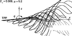
The first term in Eq. 10.127, which is the x or streamwise component of the velocity resulting from a pitch-rate q and/or a yaw-rate r, essentially produces a skewing distortion of the wake. The second term, which is the у or lateral component of the velocity resulting from a roll-rate p and/or a yaw rate r, produces a skewing in the lateral direction. The third {ax — py) term in Eq. 10.127, results in an asymmetric axial stretching distortion of the wake, which appears like a wake curvature.

In addition to the aerodynamic effects, there are inertial effects on the blade motion during maneuvers. The rotor TPP lags behind the shaft or control plane by a finite angle – see Fig. 6.32. The additional flapping moment on the blades resulting from gyroscopic effects on a rotor with pitch rate q and roll rate p is

Mg = —2 Ib^lq sin ]/ — 21ъ$1р cos + Qq cos fs + Q p sin fr, (10.128)

which must be added to the equation of motion for a flapping blade (Eq. 4.5).

……. Hover (reference)

Wake Developments in Maneuvering Flight

z A ——– Maneuver, pitch rate q= q/Q = 0.024

1.5

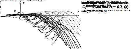
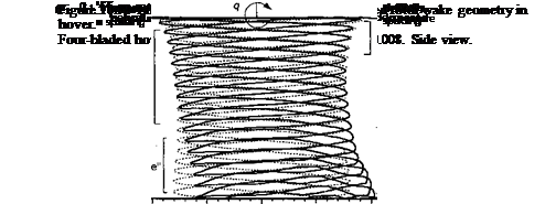
Examples of predicted free-vortex wake geometries under idealized (nose-up, positive) pitch rate conditions are shown in Figs. 10.50 and 10.51, for hover and forward flight, respectively. The imposed angular rates are relatively high for a helicopter, but they have been selected to exaggerate the basic effects obtained on the wake geometry. Notice the general characteristics manifest as a curvature-type distortion and an axial-tvpe distortion. These are physical effects that have been labeled by Keller & Curtiss (1996) as “bending” and “stretching” of the wake, respectively. Furthermore, notice that for a positive (nose-up) pitch rate, the vortex elements (tip vortices) at the front of the rotor are further way from the TPP compared to straight-and-level flight conditions. At the back of the disk, the tip vortices are much closer to the TPP. In many ways, these maneuver-induced effects on the wake distortion are similar to an increase in skewness of the wake relative to the rotor TPP. Therefore, the resulting wake distortion must manifest as a change in the longitudinal inflow distribution, which will be expected to be more biased toward the back of the disk.

Consider now a simulated piloted maneuver, such as a roll. In an actual roll maneuver the pilot banks the helicopter in one direction by applying appropriate cyclic control inputs and maintains altitude by using collective pitch. The roll rates imposed on the helicopter can be approximately described using a linearized equation for roll motion – see Padfield

(1996) . The governing equation for the roll dynamics (with the usual simplifications) can be written as

Подпись: (10.129)P 1-ipP — r^latOiat

where Lp and Ь$ы are stability and control derivatives (in roll). The solution to Eq. 10.129 for a step input of lateral cyclic, <$iat, is given by

Wake Developments in Maneuvering Flight(10.130)

The resulting bank angle is

Wake Developments in Maneuvering Flight(10.131)

Wake Developments in Maneuvering Flight

The roll trajectory can, therefore, be simulated by setting parameters such as the desired maximum roll rate and the maximum bank angle. The control inputs for the maneuvers can be generated by imposing a step input, which is then held fixed for a given duration. In this case, the asymptotic value of Eq. 10.131 is given by

Ad> = At. (10.132)

Lp –

Defining the time period over which the maneuver is performed allows the bank angle of the simulation to be determined using Eq. 10.131.

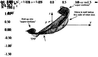
Figure 10.52 shows an example of the wake behind a rotor executing a simulated starboard and port roll maneuver. The roll to starboard delays the roll up of the wake vortices from the advancing side of the rotor disk. However, the maneuver also brings the blade tip vortices closer to the rotor at the back of the disk thereby enhancing the potential of В Vis there. The wake behavior for a port roll is similar, except that now the wake passes up more through the retreating side of the rotor disk. The port roll maneuver also causes a lag in the roll up

Wake Developments in Maneuvering Flight

y/R

Figure 10.52 Rear views of representative predicted wake geometries for a rotor under­going a roll maneuvers, CT = 0.008, ju, = 0.186, у = —6°. (a) Starboard roll rate; (b) Port roll rate. From Ananthan & Leishman (2004).

of the wake on the retreating side of the rotor because of the change in airloads over the disk. The rolled-up bundle of tip vortices trailed from the disk also move more inboard on the rotor disk and below the rotor TPP. The wake roll up on the advancing side seems to intensify during a port roll maneuver, which causes strong BVIs and high impulsive loads over the first quadrant of the rotor disk throughout the entire maneuver.

Theodore & Celi (1998) and Ribera & Celi (2004) have incorporated dynamic inflow as well as relaxation and time-accurate free-vortex wake models into a flight mechanics simu­lation for the analysis of such maneuver problems. The results showed some improvements in predicting overall trends in the free-flight response of the helicopter to cyclic inputs, but the quantitative predictions of rotor response were only marginally improved. The use of time-accurate aerodynamic modeling is clearly an enhanced approach, yet the results from this study suggest that deficiencies are still present in the aerodynamic models. There may be other mechanisms that play a role in predicting rotor airloads during maneuvers and so in eventually resolving the off-axis response problem, and the issues are still the subject of ongoing basic research.

10.12 Chapter Review

This chapter has described some of the significant problems still associated with an improved understanding of the wakes generated by helicopter rotors. The proper mod­eling of the rotor wake is one key to the prediction or rotor airloads and rotor performance. Problems such as tip vortex formation, blade-vortex interaction, and rotor-airframe inter­ference are better understood, and systematic experimental measurements have provided significant results that will help validate numerical predictions of the various phenomena. Recent advances in experimental techniques for flow visualization and 3-D velocity field measurements have been significant, and further developments will likely continue. Ambi­tious experimental tests with rotors have generated large amounts of important results that have provided new insight into old problems and remarkable insight into other problems that were previously considered intractable. However, the complexity of the helicopter rotor wake, together with the sensitivity of its topology to the flight condition, makes all types of rotor wake experiments time consuming and expensive to undertake. The challenge to the rotor analysts of the future is to balance needs with experimental capabilities and to use complementary flow diagnostic techniques wherever possible to provide an improved understanding of the various rotor wake-related phenomena.

One of the biggest challenges still remaining in helicopter rotor analysis is to reveal more completely the intricate structure of the blade tip vortices. This includes issues such as the vortex strengths, the viscous core size, and velocity field near to and inside the core, as well as their relationships to the loading on the blades. Fundamental issues such as diffusion and core growth of the vortices are not yet fully understood, and further work still needs to be undertaken to develop more general models. These models must include vortex Reynolds number effects. This diffusive behavior is compounded by interactions of vortices and blades, which causes filament stretching. Such problems cannot yet be examined using computational methods based on first principles and require careful experimental studies with rotors in both hover and forward flight. This type of research may result in new ideas for tip vortex control and possibly the alleviation of several of the complex problems involving vortex dynamics that hinder the development of quieter helicopters with better performance and lower vibration.

The long-term goal of the aerodynamic modeling efforts is to be able to predict the flow field around the entire helicopter when operating in any flight condition, including flight near the ground and during arbitrary flight maneuvers. To this end, the prediction of the rotor wake is fundamental to solving the problem. However, increasing emphasis is also being placed on rotor-airframe interaction problems (see Chapter 11) because of their importance in determining performance, vibration levels, and also the overall handling qualities of the helicopter. Rapid advances in computer power mean that prescribed vor­tex wake models are rapidly giving way to free-vortex models for many routine levels of helicopter analysis and design work. Dynamic inflow represents another formulation of the problem, where the effects of the wake can be included in a form of differential equations to represent the relationship between the time-dependent inflow velocities and the rotor forces and pitching moments. This latter approach is attractive for some problems in rotor analy­sis, particularly those in flight dynamics and aeroelasticity. All of the existing rotor wake methods are relatively powerful and can give good results, yet caution should be used. Quantitative errors can only be determined though correlation studies with experiments, and much further validation of wake models is required, particularly in improving the con­fidence in predicting the combined effects of the rotor flow and the airframe. These problems are discussed next in Chapter 11.

Descending Flight and the Vortex Ring State


The problem of the vortex ring state (VRS) has already been discussed in Sec­tions 2.13.6 and 5.7. VRS is a problem. that is not amenable to solution (prediction) by methods such as momentum theory, and more advanced prediction methods must be sought. Developments of free-vortex and vorticity transport models (see Section 14.3) have recently allowed the problem of VRS to be examined in much more detail, and for the effects of flight condition and rotor geometry on the VRS problem to be better exposed – see Brown et al. (2002) and Newman et al. (2004). However, a primary difficulty in either approach is to faithfully model the tip vortices in the rotor wake to old ages, as well as the problem of modeling accurately the physics of vortex-vortex and blade-vortex interactions. Another difficulty is that the descending flight problem is inherently unsteady, so time-accurate methods of solution such as discussed in the previous section are a necessary prerequisite.

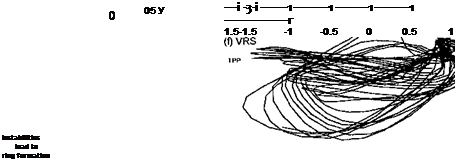
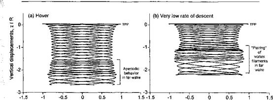
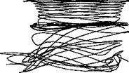
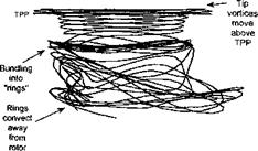
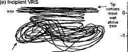
To illustrate the general behavior of the wake in descending flight, Fig. 10.49 shows views of a rotor wake that have been predicted using a FVM for a notional four-bladed rotor when transitioning from hover into axial descent. Six free-vortex turns were used to model the rotor wake; a fairly large number of wake turns must be used because the older vortex filaments can come close to the rotor disk plane as VRS is approached and accurate modeling is important here. All results show a “snapshot” of the wake at an arbitrary instant in time.

In hovering flight Fig. 10.49 shows that the wake consist of sets of nearly helical, closely interdigitated vortices, but with some evidence of wake disturbances and an aperiodic behavior in the far wake, as discussed previously in Section 10.5.1. See also Leishman et al. (2002a). For very low rates of descent there is more evidence of a wake instability and the subsequent formation of vortex perturbations. Because of the imposed descent velocity, the wake cannot be convected as far downstream below the rotor in a given time and the downstream wake filaments begin to “bundle” together. If the rate of descent is low enough then the developing bundles of vorticity are still confined to the far wake well downstream of the rotor and are convected away from the rotor as fast as they develop. For these low rates of descent the bulk of the wake is still in equilibrium and there is little or no effect on the blade airloads or rotor performance.

As the rate of descent is increased further, however, the net velocity through the rotor disk is decreased and more of the vorticity generated at the blade tips begins to accumulate near the rotor TPP. At some point, the descent velocity is high enough to cause the tip vortices to convect into the TPP after they are first formed, thereby creating a form of BVI. Notice that the developing perturbations in the wake also become more evident, and because of the higher rotor descent velocity in this case these perturbations now lie much closer to the rotor. While the wake cannot yet be considered to have “broken down” for these descending flight conditions, a characteristic feature is that parts of adjacent vortices pair together and eventually tightly clump or bundle, essentially forming toroids or vortex rings. These vortex rings themselves are not stable and naturally begin to develop a series of Kelvin waves


I


-3-


1

i


t

r

t

f


Descending Flight and the Vortex Ring State Descending Flight and the Vortex Ring State

—■ TPP


‘Bundling"

into

"rings"


-1-


Rings

break-up

and

– convert away from rotor


-2-


-2-


Descending Flight and the Vortex Ring State

1.5


Descending Flight and the Vortex Ring StateDescending Flight and the Vortex Ring StateDescending Flight and the Vortex Ring StateDescending Flight and the Vortex Ring State

Descending Flight and the Vortex Ring State

3 Подпись: Щ «К**?. | ■ і і і | | -3 і і і———– 1———— 1———– 1

-1.5 -1 -0.5 0 0.5 1 1.5 -1.5 -1 -0.5 0 0.5 1 1.5

Lateral displacements, y/R Lateral displacements, у / R

Figure 10.49 Effects of rate of descent on rotor wake developments predicted using free – vortex theory. The rotor has a solidity of 0.1, with —13° of blade twist per radius, and was operated at Cj = 0.008 with a tip Mach number of 0.65.

[see also Fig. 10.15(a)]. These waves tend to grow in amplitude and begin to affect the flow field near the rotor and so influence the rotor airloads. Nevertheless, at these relatively low rates of descent the net velocity is still mostly downward through the rotor and the vorticity associated with the wake perturbations is convected away from the rotor disk.

Figure 10.49(e) shows that the rate of descent can eventually be increased to the point that the accumulated vorticity and developing wake perturbations are within reach of the rotor TPP. Under these conditions, the aperiodic wake developments begin to affect the blade loads. There is again strong evidence of vorticity accumulation and “vortex ring” formation, but the rings convect slowly away from the rotor as they become unstable. This

condition, therefore, can be considered symptomatic of an incipient wake breakdown and a VRS onset condition. A slightly greater rate of descent then takes the rotor into the classic features of the VRS, which is usually (but imprecisely) defined on the basis of the rotor operating in the bulk of its own wake. Under these conditions the wake loses most of its well-defined structure. Of significance again is that vortex rings are formed. Because the net flow velocity at the rotor disk is now very low, these rings lie close to or pass through the TPP (compare also with Figs. 2.21 and 2.22) and the blades intersect large concentrated regions of accumulated vorticity. This leads to locally high unsteady blade airloads and large fluctuations in rotor thrust, which are known characteristics of VRS (Section 5.7). Notice that these vortex rings are also unstable and themselves exhibit evidence of Kelvin waves that quickly grow in amplitude, causing the rings twist over and forming a series of knots. Eventually the rings themselves break down and their associated vorticity is convected away from the rotor. Notice that because of the small axial (slipstream) velocity near the rotor at this rate of descent, most of the vorticity is convected radially (and not axially) away from the rotor disk. This process of vorticity accumulation and vortex ring formation is not necessarily periodic, but the basic process of ring formation, ring breakdown and convection of the accumulated vorticity away from the disk is repeated for as long as the rotor operates in the conditions that would promote it. See also Section 14.10.7 for further results on the VRS problem.

General Dynamic Inflow Models

In many cases it is desirable to directly account for unsteady effects on net rotor forces and pitching moments. While the localized unsteady aerodynamic effects are clearly complicated, for some problems it is useful to seek a more global approach to modeling their
effects. This comes under the classification of dynamic inflow or so-called finite-state wake models. The principles range back to those of the steady inflow model used by Mangier & Squire – see Section 3.5.2. The idea in the dynamic inflow model is that the effects of the wake can he represented as a set of ODEs, that is, in state-space form. Consider, for example, a maneuver, where the unsteady effects will cause the inflow through the rotor to be different from that produced under steady level flight conditions. This will change the rotor forces and pitching moments, and so the rotor flapping response will be affected. See also Curtiss & Shupe (1971). The essence of these ideas can be attributed to Sissingh (1952), Carpenter & Friedovich (1953) and Joglikar & Loewy (1970), but many variations of the dynamic inflow theory and applications thereof have appeared in the literature. Crews et al. (1973), Ormiston (1976), Peters (1974), and Curtiss (1986) have put forth variations of the dynamic inflow theory and have showed that the effects can have an influence on rotor response and various problems in rotor dynamics and aeroelasticity. The most popular model of dynamic inflow is that of Pitt & Peters (1983), which has seen several applications in the literature – see Gaonkar & Peters (1986a, b) and Peters & HaQuang (1988). The ideas can also be extended to represent unsteady effects on 2-D airfoils – see Peters & He (1995).

Momentum theory can be used to relate the aerodynamic forces and pitching moments on the rotor to the inflow across the disk (see Chapter 2). The thrust, T, can be represented by the integral of the change in momentum through the rotor disk, that is,

pR рЪт

T — 2p I I v2r dxfr dr, (10.119)

Jo Jo

where v is the inflow velocity. Similarly, the pitching moment (positive nose-up) will be given by

Подпись: (10.120)

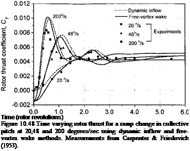
Подпись: Time (rotor revolutions) Figure 10.48 Time varying rotor thrust for a ramp change in collective pitch at 20,48 and 200 degrees/sec using dynamic inflow and free-vortex wake methods. Measurements from Carpenter & Friedovich (1953).

pR p2n

My =—2p I I v2r2 cos т/г d{f dr Jo Jo

and the rolling moment (positive roll to starboard) is given by

p R ріж

Mx = —2p I I v2r2 sinyj/ d}r dr. (10.121)

Jo Jo

A key assumption is the form of the inflow distribution over the rotor disk. As Section 3.5.2 has shown, a popular assumption is to use a linear distribution of the form

v = v(r, ifs) = Vo + vcr cos і(r + vsr sin ifr, (10.122)

where vo, vc, and ^ are the uniform, longitudinal, and lateral contributions to the inflow, respectively. This allows a coupling of the rotor thrust and pitching moments to the induced velocity field. This can be written in matrix form as

Подпись:(10.123)

where [L] is a coupling or “gain” matrix. The subscript “aero” implies that only aerodynamic contributions are to be included; rotor inertial terms are omitted. In a local momentum analysis of the problem, the [L] matrix is a diagonal matrix, where vo is related to Ct, vc is related to Сму, and is related to Cmx. These relations, however, may be coupled and the matrix will be fully populated. In forward flight, the coefficients in the gain matrix also become functions of the wake skew angle. Gaonkar & Peters (1986a, b) review the development of the gain matrix, although it appears that more experimental verification may be required to validate the assumptions made.

The ideas of a time lag in the development of the wake are introduced through the use of a time constant matrix [r] = [L][M], where [M] is a matrix of unsteady terms. The dynamic inflow model is now written as

Подпись:Подпись:(10.124)

or

(10.125)

These ODEs can be used to relate the unsteady inflow to the rotor thrust and pitching moments. The time constants are also functions of the wake skew angle, which are derived from vortex theory. In the complete problem, the equations of motion of the blades must be introduced using a blade element approach. This provides the complete relationship between the blade loads, the rotor inflow, and rotor response.

Many refinements of the basic dynamic inflow approach can be found in the literature. The coupling and time-constant matrices have been derived from a number of other theories, including actuator disk and vortex theories. For extensive information on dynamic inflow modeling, see Johnson (1980). The most recent work on dynamic inflow has been put forth by Peters and colleagues – see Peters et al. (1987), Peters & HaQuang (1988), Peters & He (1989,1995), Peters et al. (1995), and Morillo & Peters (2002). Their work also encompass the classical theories of Theodorsen (Section 8.7) and Loewy (Section 8.8).

Dynamic inflow models have found utility for various problems in rotor aeroelasticity, as well as for helicopter flight dynamics – see Chen (1989) and Padfield (1996). However,

the dynamic inflow model is limited in that it is fundamentally a linear model. Other new approaches toward the development of dynamic inflow models in state-space form have examined the transformation of the equations governing free-vortex wakes into a system of general ODEs – see Celi (2004). These “wake” ODEs can then be coupled to other equations describing other aspects of helicopter performance or behavior, or can be used to extract so-called “linearized” models for use in flight dynamics applications. Another such approach to the formulation of a wake model in state-space form using indicial theory is described by Johnson (1988).

Simulation of Carpenter & Friedovich Problem

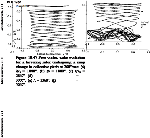
The time-marching free-vortex wake model can be applied to compute the evo­lution of the vortical wake structure for the Carpenter & Friedovich (1953) problem, as described in Section 10.8.2. Representative results are shown in Fig. 10.47 at selected times after the collective pitch input was applied. It is apparent that the trailed vortices initially pair off and bundle up below the rotor to form a vortex ring, as shown previously by the flow visualization images in Figs. 10.44 and 10.45. Immediately after the collective pitch input is applied the vortices trailed from the blade tips convect only relatively slowly away from the rotor because of the initially low thrust and low induced inflow through the rotor. In fact,

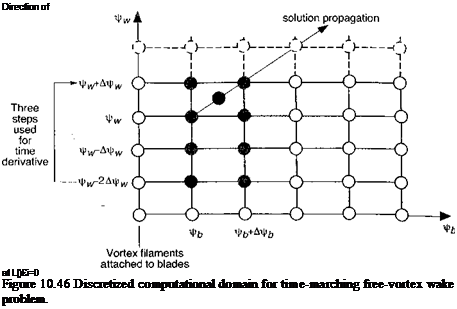
Подпись: Direction of at Ц)£і=0 Figure 10.46 Discretized computational domain for time-marching free-vortex wake problem.

by comparing the helicoidal pitch of the computed wake at early times versus later times in each case, it is apparent that the net inflow through the rotor builds up only relatively slowly over several rotor revolutions. Initially, therefore, the tip vortices lie in close proximity to each other, and their respective induced velocities create a tendency for them to pair about each other. This pairing tendency is clearly the main reason for the formation of a ring of bundled vorticity immediately below the rotor plane.

After the wake begins to develop and the inflow through the rotor increases, the newer trailed vortices begin to convect in a relatively higher wake velocity, and the starting ring is convected further down in the wake below the rotor. Notice that in each case the starting vortex structure is unstable and begins to show the presence of pronounced sinusoidal deformation modes or Kelvin waves (see Section 10.5.2). These waves grow in amplitude with time, and eventually cause the initial starting ring vortex system to break down as it convects into the far wake below the rotor. As the rotor induced inflow then approaches a steady-state value, the vorticity associated with the vortex ring is convected downstream well away from the rotor blades. After about 4-6 rotor revolutions (although this depends on the time rate of change of collective pitch), this starting wake has been convected about one and a half rotor radii below the rotor. At this point, any wake perturbations have been convected sufficiently far away from the rotor such that their influence on the rotor aerodynamics becomes small. The rotor wake then approaches a steady-state (periodic) condition with the vortex wake structure then taking on its more characteristic helicoidal form.

Figure 10.48 shows the predicted results of the rotor thrust for three values of the collec­tive pitch rate (20,48, and 200° per second) along with Carpenter & Friedovich’s measure­ments. In each case, the predicted time-history of the rotor thrust response using either the dynamic inflow or free-vortex wake method shows good agreement with the experimental measurements. Notice that there is a lag in the development of the rotor thrust, which builds up and reaches its final value in about 2 to 4 rotor revolutions, depending on the collective pitch input rate. The intermediate values of the thrust show significant overshoots before

Simulation of Carpenter &amp;amp; Friedovich Problem
settling down to their final values. For the highest ramp rate of 200 deg/s, the thrust over­shoot is about twice the steady-state value, confirming the significant effects of transient blade pitch inputs on the overall rotor wake evolution and blade airloads. Remember that the physics of this problem and the reasons for the lift overshoots is governed mainly by the temporal evolution of the vorticity trailed into the rotor wake, so that the lag in inflow development through the rotor is really a circulatory effect.

Time-Marching Free-Vortex Wakes

trrtH-av км ofli sA n tl г11 т 7 /–м /Л л-Р fU/% Іл лпі – Ілчгліп лР

iiinc-iiicu^mng 1100-vuil^a ij. it/Liiuua |juLt/iitiauj unci uiic vji 1110 ucai ic^voia ui

Time-Marching Free-Vortex Wakes Подпись: (10.118)

approximation to the rotor wake problem, and also with the fewest restrictions in application. In a time-marching algorithm the time evolution of the position vectors of each wake Lagrangian marker can be expressed by

As shown previously in Section 10.7.3 a second-order, five-point central difference ap­proximation can be used to find the spatial (J/W) derivative, and the right-hand side of Eq. 10.118 can be represented discretely as F (r(jfb), ^). Time-marching algorithms can also take advantage of the numerical improvements produced by a predictor-corrector se­quence. Although any initial wake geometry can be specified from which to march the solution, the initial or starting induced velocity field is usually a relaxation solution. This helps minimize nonphysical transients (and numerical costs) associated with defining the initial condition. Unfortunately time-marching methods have proven susceptible to insta-

Kilifi/ac rocnlfinгг frAm mitiotinn rf mimpripal miprnctm^tnrae Гeaa TiV»orri/of JPr T aiclitnon

uniuvo ivouiviii^ uv/ui uxv iintiuwxvxi vi uuiuvuvui iiuvx vuu uviujl vj |^ow jLiiiugrvui cv juviouuiuu (2000b, 2001a)], thereby reducing the confidence that a physically realistic wake solution has been obtained. Properly distinguishing between the known physical instabilities of rotor wakes and those that are numerical in origin have proven to be a major hindrance in the development of reliable and robust time-accurate vortex wake models for helicopter rotor applications.

Bhagwat & Leishman (2001a) have used a five-point central difference scheme for both the spatial derivative and the temporal derivative in Eq. 10.54 during the predictor step, and a five-point central difference scheme for the spatial derivative and a three-point second-order backward difference scheme for the temporal derivative in the corrector step. This stencil is then swept over the computational domain – see Fig. 10.46. A Taylor’s series expansion, around the cell evaluation point shows that leading terms in the expansions of the difference approximations are 0(А^|) and O(AV^), so the time-marching approximation is second – order accurate in both space f/b and time frw.

Dynamic Inflow

The forgoing description of a physical behavior forms a fundamental basis for the development of nonsteady (and perhaps aperiodic) wake models. Carpenter & Friedovich (1953) attributed the buildup of the mean rotor inflow and rotor thrust to inertia effects in the flow. To model this behavior, a dynamic inflow equation was formulated by equating the rotor thrust obtained using differential momentum theory to that using blade-element theory (i. e., the BEMT discussed in Chapter 3). Unsteady inflow effects were modeled using the concept of an apparent mass (inertia), where the thrust equation (as given by the momentum theory in Chapter 2) is modified by the addition of an unsteady term to give

Подпись: ,2 ... ( . 2 л  (10.108)

The term ma was associated by Carpenter & Friedovich (1953) with the apparent mass of an impermeable (solid) circular disk accelerating in a stagnant fluid, that is, a noncirculatory effect. It was further suggested that this apparent mass to be 63.7% the mass of a sphere of fluid with a radius equal to the rotor radius, that is,

Dynamic Inflow

The mabi term, therefore, is meant to represent the additional reaction force on the rotor disk because of the accelerating inflow. However this concept assumes an equivalence between the force on a solid disk accelerating in a stagnant fluid and the force on a fluid accelerating through a permeable actuator disk. Such an equivalence is certainly not rigorous but the derivation can proceed on this basis. Using the blade element theory (see Section 3.3), the elemental thrust including blade flapping is given by

dT = ^NbpcC[a (б – Q2r2dr. (10.110)


Assuming a rectangular blade planform (i. e., c(r) = c) and uniform inflow (i. e., u,(r) = uf) the total rotor thrust can be found by integrating the above equation to get

т = [ат = ъИьрсС^кг{в-т-ъ)-

Equating the two thrust expressions (Eq. 10.108 and 10.111), an equation governing the dynamic inflow through the rotor can be derived. Notice that the inflow dynamics is coupled with the blade flapping dynamics, and a second equation governing the blade flapping angle can be found by moment equilibrium about the flapping hinge, as described previously in Chapter 4. In nondimensional form Eq. 10.111 becomes


P

3


Dynamic Inflow

2


h + i


в

3


Ct


(10.112)


Therefore, the governing equation for the inflow dynamics can be written as


Dynamic Inflow

A,

2


(10.113)


2A{ А,- + – /3


Dynamic Inflow

To determine the approximate time constant of the developing flow, Eq. 10.ІІ5 can be linearized about a mean operating state using А,- = A; + <$A; and Ст = Ст + 8Ct, which after simplification and neglecting terms of О (Ski)2 gives


Oaii+ai=(i)sCr – (ioil6)

This is an ODE that relates the change in inflow, 5A;, to the change in rotor thrust, 8Ct – The time constant of this dynamic system is


0.849

4AIT2’


(10.117)


Dynamic InflowDynamic Inflow

For a typical helicopter rotor where X,- ~ 0.05 and Q ъ 40 rad/s, will be of the order of 0.1 seconds. The dynamic adjustments that take place in the time averaged inflow are, therefore, relatively rapid in real time. However, it will be noted that a time lag of 0.1 seconds corresponds to over half a rotor revolution, so at the local (blade element) level the local adjustments to the flow do, in fact, occur over relatively long aerodynamic time scales in terms of wake age or semi-chords of blade travel.

Flow Visualization of Transient Rotor Wake Problems

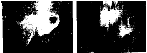
There are only a few experiments that have visualized the wake evolution of a helicopter rotor under nonsteady or transient operating conditions. The first was conducted by Taylor (1950) for a rotor with fixed collective pitch being impulsively started from rest. The balsa dust technique was used to seed the flow, which was illuminated by a light source. Figure 10.44 shows two images of the developing wake structure in a plane in the wake that intersects the rotor axis just shortly after the rotor was started. Of interest is that the wake shows evidence of a transient starting flow in the form of a vortex ring. This vortex ring is analogous to a starting vortex system for a wing set into rectilinear motion or undergoing a sudden change in angle of attack (i. e., the Wagner problem discussed in Section 8.10).

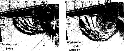
Results showing the formation vortex rings in a rotor wake were given by Carpenter & Friedovich (1953) for rapid increases in blade collective pitch and are also shown by Jessurun et al. (2001) for both rapid collective and cyclic pitch inputs. An example is shown in Fig. 10.45 from the work of Carpenter & Friedovich (1953), where it is apparent that the individual tip vortices pair-off in the wake below the rotor during the initial stages of wake development and soon form into coherent bundles of almost toroidal rings of concentrated vorticity. Just after the collective pitch input is applied the tip vortices can only convect relatively slowly away from the rotor because of the initially low thrust and low induced inflow. Therefore, the tip vortices initially lie in close proximity to each other, and their respective induced velocities create a tendency for them to pair about each other. This pairing tendency is the main reason for the formation of a ring of bundled vorticity immediately below the rotor plane.

Flow Visualization of Transient Rotor Wake Problems

After the wake begins to develop and the inflow through the rotor increases, the newer trailed vortices begin to convect in a relatively higher wake velocity, and the starting ring is convected further down in the wake below the rotor. These vortex rings are present in

Flow Visualization of Transient Rotor Wake Problems

(a) Early time


(b) Later time


Location


Figure 10.45 Flow visualization images in a vertical plane through the rotor axis showing that pairing of individual tip vortices gives rise to the starting vortex ring, (a) Early time, (b) Later time. Source: Carpenter & Friedovich (1953).


Flow Visualization of Transient Rotor Wake Problems

the rotor wake for several subsequent rotor revolutions and can have a substantial effect on the overall time-history of the resulting wake developments, the developing inflow, and on the blade airloads. Also apparent from the various flow visualization studies that these starting rings of vorticity begin to break down as they are convected further away from the rotor. This suggests that the accurate modeling of close vortex filament interactions as well as the time accuracy of the problem will be critical in establishing good predictions of the overall rotor airloads when the flight controls are being manipulated under maneuvering flight conditions.