Category Principles of Helicopter Aerodynamics Second Edition

Wake Stability Analysis

The tendency of a helicopter rotor wake toward developing an instability is an in­herent characteristic because of the naturally unstable deformation modes associated with its helicoidal form. Various aerodynamic disturbances inherent in nature, or physical dis­turbances associated with the manner in which the rotor is operated, usually provide the conditions necessary to excite the equilibrium wake geometry and cause it to exhibit per­turbations. This problem has been examined theoretically by Levy & Forsdyke (1928), Widnall (1972), Gupta & Lowey (1974), and Bhagwat & Leishman (2000b). In particular, a local long-wave wake perturbation known as vortex “pairing,” has already been mentioned in Section 10.5.2. This is a combined low-frequency/long-wavelength radial and axial de­formation mode and has been observed in several rotor wake experiments, for example, Tangier et al. (1973), Martin et al. (1999), and Caradonna et al. (1999).

While wake instabilities seem common enough in experiments documenting rotor wakes, in computational modeling it is the omnipresent numerical truncation and round-off errors that potentially initiate wake instabilities. Properly distinguishing between the consequences

of physical and numerical wake instabilities has been a long-standing problem in helicopter aerodynamics. This problem was examined by Bhagwat & Leishman (2000b) using vortex theory and also by Martin et al. (1999) in rotor experiments designed to deliberately pro­mote wake instabilities. A two-bladed rotor wake was shown to develop a primary mode of instability with a wave number at the rotational frequency of the rotor. This mode it seems, is relatively easy to excite in a real rotor flow field, such as by blade mistracking. The argu­ment can be carried forth to rotors with greater numbers of blades, where the susceptibility to develop wake instabilities always increases with blade number. This fundamental char­acteristic behavior of rotor wakes is key to how various forms of physical wake instabilities actually arise in practice.

Wake Stability Analysis Подпись: (10.102)

The stability of a rotor wake can be examined mathematically from a perturbation analy­sis. From the equilibrium solution for the wake, such as by using vortex theory, the solution is then perturbed by a small quantity, Sr, with the new geometry being described by r + Sr. The governing equation for this perturbed wake geometry is given by

The equation governing the perturbation wake displacement, Sr, is obtained by subtracting the equilibrium equation from the perturbed equation (Eq. 10.102) giving

d{8r)

= V(r + Sr) – V(r). (10.103)

dt

Подпись: VC* Подпись: Sr Подпись: /1П 1 fA V J. v. iu*+)
Wake Stability Analysis

The induced velocity on the RHS of Eq. 10.102 can be expressed as a Taylor series in Sr as

Подпись: d(Sr) dt Подпись: SV{8r), Подпись: (10.105)

This can now be linearized by neglecting higher-order terms in Sr to give

which is the equation governing the perturbation problem.

Подпись: №1 = Подпись: Sr0 <500 <5zo Подпись: eat+ia>^ Подпись: (10.106)

For the solution of Eq. 10.105, perturbations to the wake can be assumed to be in the form of a normal mode (or a traveling wave) along the lengths of the vortex filaments – see Saffman (1992) and Bhagwat & Leishman (2000b). Because of the helicoidal nature of the rotor wakes, cylindrical polar coordinates can be used. In this case the normal mode perturbation is given by

where or is the growth rate and to is the wave number, that is the perturbation wave has со cycles for each rotor revolution. The governing equations for each perturbation mode can then be solved at a given point P on the vortex filament. The velocity contributions of all the vortex elements are summed using the Biot-Savart law to obtain the total induced velocity perturbation in matrix form as [F] = [u,]. After some manipulation, the problem can

І

be reduced to a standard eigenvalue problem with the form

Подпись: (10.107)otp{x} = [M]P {*},

where M is the fundamental solution matrix for the wake, the evaluation of which is completely described by Bhagwat & Leishman (2000b). The eigenvalues aP give the growth

Wake Stability Analysis

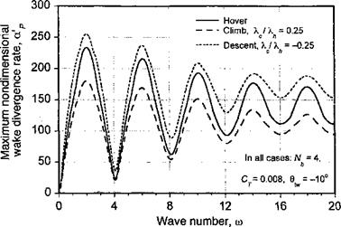
Figure 10.43 Maximum nondimensional wake divergence rates as a function of wave number со for a four-bladed rotor in axial flight (hover, climb, and descent).

rate of the perturbation at a point P on the vortex wake. A positive growth corresponds to an unstable wake mode, a zero growth rate is a neutrally stable wake mode, and a negative growth rate is a stable wake mode.

The advantage of this type of mathematical approach is that the fundamental stability of the rotor wake can be understood in terms of its characteristics (shape and circulation strengths) and, therefore, how the stability of the wake is affected by the various geometric and operational characteristics of the rotor. For example, climbing or descending flight changes significantly the helicoidal pitch of the rotor wake structure, and so this must affect the overall wake stability. The rotor thrust (disk loading) and blade twist are also known to be factors that affect the stability of the rotor wake.

Figure 10.43 shows an example of the stability characteristics of a rotor wake in axial flight. The wave numbers corresponding to the extrema in the wake divergence rates correlate with the number of interdigitated tip vortex filaments (or blades). On one hand, the maximum divergence rate occurs at wave numbers equal to half-integer multiples of the number of blades, that is, at wave numbers со = (к + 1/2)Nb for all integer k. On the other hand, a minimum divergence rate occurs at integer multiple of the number of blades, that is for со = к Nb. With increasing wave number, the difference between maximum and minimum divergence rates decreases, indicating that for very large wave numbers the divergence rates would be independent of wave number. However, the increasing growth rates for large wave numbers with increasing number of filaments suggests an increased overall susceptibility to wake instabilities, say those that might be produced by random disturbances or turbulence in the flow.

‘rhis figure also shows that a climb velocity decreases the wake growth rates (i. e., the wake is less susceptible to instability and to forming wake perturbations). This is because of the increased helicoidal spacing between adjacent wake filaments. The results in Fig. 10.43 also show that for the descending rotor a more substantial increase in growth rates are obtained for wake modes at the higher wave numbers. This implies an increased suscep­tibility to instability and to forming wake perturbations in descending flight. These might be triggered by the higher-frequency unsteady airloads generated at the rotor, or by atmo­spheric turbulence, rather than by larger-scale disturbances in the surrounding flow. This
observation may be key to the full understanding of the initiation mechanisms of wake instabilities. However, it may also prove to be an impediment to the achievement of reliable numerical predictions for rotor wakes under various descending flight conditions because of the need to model the source of these disturbances.

Aperiodic Wake Developments

There are many applications in helicopter aerodynamics for which quasi-steady or periodic wake methods are unsuitable because the physics of the rotor wake cannot be assumed globally periodic. Such unsteady environments include rapid changes in pilot control inputs, some types of rotor wake-airframe interaction problems, flight operations near the ground, maneuvering flight conditions, autorotational flight, or when descending flight near the vortex ring state (VRS). These problems often result in various forms of disturbances in the wake that result in instabilities. The instabilities are aperiodic with respect to the rotor frequency, and so they can change fundamentally the physical structure of the rotor wake topology. Examples of wake perturbations that result in instabilities have been shown previously in Fig. 10.15. Furthermore, the rotor wake is often found to be aperiodic in hovering flight. This behavior has its source in natural instability modes of helicoidal vortex filaments.

Accurate simulations of these types of problems requires fully time-accurate wake meth­ods, which raises substantially the complexity of the modeling. Of particular practical interest is the rotor behavior under maneuvering flight conditions, for which a fully ade­quate wake model continues to elude helicopter analysts. A maneuver often sets a limit to the normal flight envelope of a helicopter so the prediction of the rotor airloads under these conditions forms an important part of the design process (see Section 5.9). Under these conditions the pilot uses cyclic pitch control inputs to place the helicopter in a variety of nonsteady flow states. The wake develops in a time-dependent (aperiodic) manner, and the inflow through the rotor acquires a history or hereditary effect. This problem is similar to the unsteady airfoil problems discussed in Chapter 8, although for an entire rotor the problem is considerably more 3-D and clearly much more complex.

Comparisons of Vortex Wake Models with Experimental Data

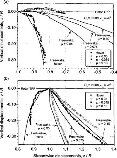
To demonstrate some aspects of the predictive capabilities of free-vortex wake models, comparisons are now shown with experimentally determined wake geometries in hover and forward flight. Figure 10.38 shows a comparison of predicted and experimental wake boundaries at the longitudinal centerline of the rotor (see also Fig. 10.10). It can be seen that during the transition from hover to forward flight, there are significant changes to the wake geometry, and so these cases provide a good general test of the capabilities of any vortex wake model, free or prescribed.

In hover, the wake is (theoretically) axisymmetric: so the leading- and trailing-edge wake boundaries are identical. For a variety of reasons, this is not necessarily the case for the experimental measurements, but the overall differences are small. As the advance ratio is increased, note that the wake is quickly skewed back by the free-stream flow. Figure 10.38 shows that as the newer tip vortices at the front of the rotor disk move downstream, they are convected over the top of the following blade. As the vortices are convected further downstream, they begin to descend toward the TPP and are ultimately intersected by a blade producing a perpendicular type of BVI.

At the rear of the rotor disk, however, there is a higher downward induced velocity component, and the vortices remain well below the TPP. As a consequence, the wake skew angle at the rear of the disk is much smaller than at the leading edge of the rotor. It can also be seen from Fig. 10.38 that while the free-vortex wake model shows a high sensitivity to small changes in advance ratio, the streamwise displacements are somewhat underpredicted compared to the experimental results. Some of these differences, however, can be attributed to experimental uncertainties in the measured data. Overall, the results from the free-vortex wake model are found to be in much better agreement with the measurements than are those of the rigid wake representation.

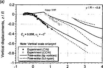
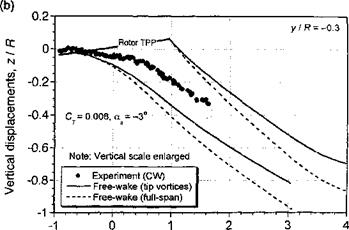
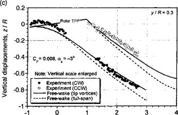
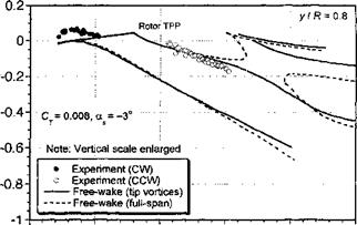
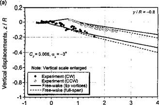
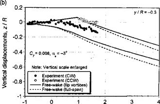
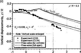
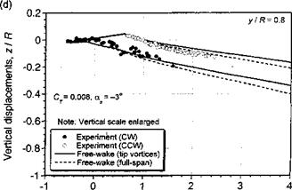
Further comparisons of the free-vortex wake model with measured tip vortex displace­ments in the x-z plane are shown in Figs. 10.39 and 10.40 for two advance ratios and for four longitudinal planes through the wake. The data have been taken from Ghee & Elliott

(1995) , who have measured the displacements of the tip vortices using a planar laser sheet technique. Data were measured at four longitudinal planes at y/R = ±0.3 and y/R = ±0.8. At the inner locations, some gaps occur in the measured data because the fuselage and rotor hub blocked access for flow visualization. Free-vortex wake predictions have been made using both a full-span vortex sheet, and just with the tip vortex alone. We see that for both advance ratios, the free-vortex wake prediction are in good agreement with the measured

Comparisons of Vortex Wake Models with Experimental Data

Figure 10.38 Predicted wake boundaries in hover and forward flight using free-vortex wake scheme compared to measured data, (a) Front of rotor, (b) Rear of rotor. Four-bladed rotor, with CT = 0.008 and = —3°. Data source: Leishman & Bagai (1991).

tip vortex displacements. Clearly there are some difference between the predictions and experiment, but the overall quality of the results are good, bearing in mind the complexity of the physical problem. The effect of including a full-span wake compared to a single-tip vortex is relatively small, so its inclusion may not be justified given that the numerical cost of this approach is greater by about one order of magnitude. However, the inclusion of the inner wake sheet may be required to ensure proper predictions of rotor performance.

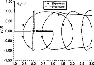
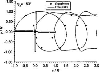
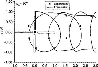
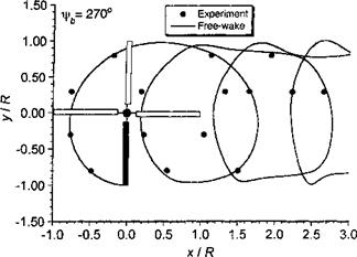
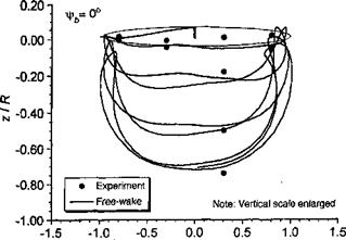
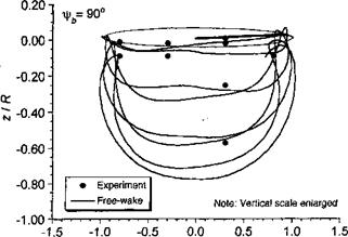
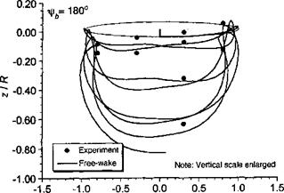
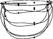
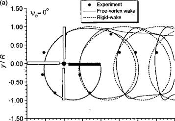
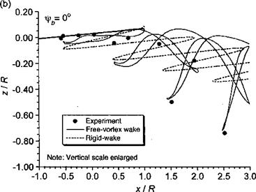
Figures 10.41 and 10.42 show the plan and rear views of the rotor wake at an advance ratio of 0.15. The tip vortex trajectories trailed from each blade have been plotted separately to ensure clarity. Again, the results are compared with the measured tip vortex displacements as the vortices intersect the four longitudinal planes. When viewed from above, the trajec­tories are relatively undistorted from their epicycloidal forms. It is only at the lateral edges of the wake that distortions occur because of the roll-up between individual vortices. The rear

Comparisons of Vortex Wake Models with Experimental Data

Comparisons of Vortex Wake Models with Experimental Data

(d)


Comparisons of Vortex Wake Models with Experimental Data

-1


Comparisons of Vortex Wake Models with Experimental DataComparisons of Vortex Wake Models with Experimental DataComparisons of Vortex Wake Models with Experimental Data

Streamwise displacements, х / R

Streamwise displacements, x / R

Figure 10.39 Predicted wake boundaries in forward flight compared to measurements, /z = 0.15; CT = 0.008;a* – 3°. (a) y/R = —0.8, (b) y/R = —0.3, (c) y/R = 0.3, (d) y/R = 0.8. Data source: Ghee & Elliott (1995). (

OS

4^


Comparisons of Vortex Wake Models with Experimental DataComparisons of Vortex Wake Models with Experimental Data

Streamwise displacements, x / R

Streamwise displacements, x / R

Comparisons of Vortex Wake Models with Experimental DataComparisons of Vortex Wake Models with Experimental Data

Streamwise displacements, x / R Streamwise displacements, x / R

Figure 10.40 Predicted wake boundaries in forward flight compared to measurements, /n = 0.23; CT = 0.008; as — 3°. (a) y/R = —0.8. (b) y/R = —0.3. (c) y/R = 0.3. (d) y/R = 0.8. Data source: Ghee & Elliott (1995).


0

t-o

Lft


Figure 10.41 Predicted plan view of rotor tip vortex geometry compared to measurements, (а) т=0°. (b) fa = 90°. (c) ^ = 180°. (d) ij/b = 270°; /X = 0.15; CT = 0.008; as — 3°. Data source: Ghee & Elliott (1995).


Comparisons of Vortex Wake Models with Experimental DataComparisons of Vortex Wake Models with Experimental DataComparisons of Vortex Wake Models with Experimental DataComparisons of Vortex Wake Models with Experimental Data

(а)


(b)


Comparisons of Vortex Wake Models with Experimental Data

(С)


ylR


Comparisons of Vortex Wake Models with Experimental DataComparisons of Vortex Wake Models with Experimental DataComparisons of Vortex Wake Models with Experimental DataComparisons of Vortex Wake Models with Experimental Data

Comparisons of Vortex Wake Models with Experimental Data

Figure 10.42 Predicted rear view of rotor tip vortex geometry compared to measurements, (a) xlrb = 0°. (b) – фь = 90°. (c) fb = 180°. (d) == 270°. ft = 0.15; Ct — 0.008; as — 3°. Data source: Ghee & Elliott (1995).

Comparisons of Vortex Wake Models with Experimental Data

views of the wake shown in Fig. 10.42 vividly show this roll-up process and the formation of vortex bundles or “super-vortices,” a phenomenon previously mentioned in Section 10.4. In these regions, the small radius of curvature of the vortex filaments requires a relatively small levels of discretization; the present calculation has used A^ = Afrw = 5°, and the good correlations obtained with the measured data in these regions confirms that, at least in this case, this is an adequate level of discretization.

General Numerical Trim Model

To conduct a validation of any wake model with experimental measurements, the rotor must be trimmed, and this requires an iterative procedure. For simplicity, only the rotor will be considered^ but as shown in Section 4.14 the airframe must also be considered for a proper free flight trim simulation. Recall that the rotor aerodynamic response, in general, is a highly coupled function of the control inputs and rotor aerodynamic environment. Therefore, although rotor thrust is controlled by the application of collective pitch, the blade flapping response is also affected. Likewise, cyclic pitch inputs not only produce a change in blade flapping response, but in rotor thrust as well. This coupling is a result of the induced aerodynamic effects trailed into the rotor wake, and its effect on the angles of attack over the rotor disk. The procedure necessitates several trim iterations before a converged solution is obtained.

The updates to the rotor control inputs at each trim iteration can be found using a Newton – Raphson approach applied to a linearized system of coupled equations that relate the rotor response vector to the control vector. If the control input vector is denoted by 3c, and the rotor response or output vector by y, then

‘ Oo

Ст

у _ ,

0c

’ and

V = –

Pic

0s

у

Pis

A first order Taylor expansion for the rotor response about x gives

Подпись: (10.98)y(* + Ax) = y(x) + [У] Ax H———

where y(x + A3c) is the rotor response as a result of the new control input vector {x + Ax}. Rearranging the terms in Eq. 10.98 gives

Ax = [j~l]{y(x +Ax)-y], (10.99)

where {у(х + Ax) — y} is a response error vector that will be denoted by ?(>■). Hence, Eq. 10.99 can be written in the following compact form

АЗс = [7_1]б(у). (10.100)

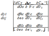
The matrix, [У] is known as the Jacobian matrix of the dependent quantities (response variables) in terms of the control inputs, and in terms of constituent elements is given by

Подпись:(10.101)

Notice that if the flight controls were uncoupled then [J] would have been a diagonal matrix with no interdependency between either the rotor thrust and cyclic inputs or between the

blade flapping and collective input. However, because of the complex 3-D aerodynamic coupling at the rotor, the Jacobian is fully populated.

To solve Eq. 10.100 numerically, the Jacobian matrix must first be determined. The partial derivatives in Eq. 10.101 can be approximated using first-order forward differences. This is done by first computing the rotor response vector corresponding to an initial guess control input vector. Subsequently, each input is independently perturbed and the rotor response recomputed to provide all the elements of [7]. Although computationally expensive to evaluate, for most problems the Jacobian matrix does not need to be recomputed each time the rotor is trimmed. The control input correction or update vector, Ax can be readily determined by solving Eq. 10.100 using standard matrix methods. The rotor control inputs can then be updated. Usually, however, some degree of numerical damping must be provided to ensure monotonic convergence of the solution to within a specified tolerance in rotor thrust and rotor flapping response.

Numerical Characteristics of Free-Wake Models

Numerical Characteristics of Free-Wake Models

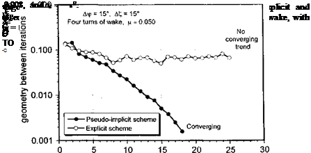
The advantage of using an implicit or pseudo-implicit FVM is that many of the numerical and round-off error problems associated with explicit methods can be avoided. Typical convergence characteristics of an explicit and a pseudo-implicit FVM are shown in Fig. 10.36 for a relatively low advance ratio of 0.05, where the self – and mutually induced

effects from the tip vortices are strong. In each case, four complete turns of the free-vortex wake were used with a relatively coarse 15° azimuth step (A^0> = Ai/rw = 15°).[41] The

Подпись: .і., „

Numerical Characteristics of Free-Wake Models

explicit scheme initially shows a converging trend, but only readies a minimum Єног ot about 0.05 after eight iterations. Further iterations cause numerical oscillations in the wake geometry and thereafter slowly drive the solution unstable. In contrast, the pseudo-implicit method essentially shows a monotonically converging solution, which converges below an acceptable error threshold after about fifteen iterations.

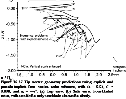
A comparison of the corresponding wake geometries at the end of the iteration cycles is shown in Fig. 10.37. Notice that with the explicit scheme there are several regions of the wake where the numerical errors have propagated, and there are significant signs of developing
instabilities that, based on experimental studies of helicopter rotor wakes [e. g., Lehman (1968) and others], are clearly not of physical origin. These are undesirable characteristics of free-vortex wake schemes using explicit integration schemes that make them unsuitable for rotor flow field predictions.

Acceleration Methods

Various ideas have been used to decrease these computational times and make the FVM more attractive for various helicopter applications. Often, methods can be used to differentiate between vortex elements in the “near field” and “far field,” the latter which have a smaller influence and can be either excluded from the calculation altogether or can be included by lumping together the induced effects of several “far” elements. Miller & Bliss (1993) have employed an analytical and numerical matching technique, in which a near field solution for the vortex near the core is matched to a far field solution. Substantial reductions in computational cost are possible. An extension of this approach is discussed by Miller (1993). Although successful in decreasing execution times, the resulting higher-order velocity field errors associated with the approximations may still undermine the accuracy of the wake predictions. Linear interpolation of the positions of the wake markers, such as discussed by Brooks et al. (1996), simply to effect a larger number of points does not improve the net accuracy of the wake solution. Sarpkaya (1989) discusses other methods that can potentially be used to reduce the computational time of vortex methods.

Bagai & Leishman (1998) have approached the problem through adaptive refinement of the finite-difference grid used to solve the governing equations of the vortex wake, with inter­polation of known information onto intermediate points in the wake. Reductions in compu­tational effort of over an order of magnitude are possible. The underlying goal is to perform fewer explicit induced velocity calculations using the Biot-Savart law, while retaining the

accuracy and fidelity of the wake solutions. For equal discretization (Aif/b = Ax(/W) with Щь = 2n/Aif/b azimuthal steps per rotor revolution, the number of vortex segments in each wake turn is — N^b = N. Therefore, the number of Biot-Savart calculations

required is Nh N^h = NbN2. (Without periodicity assumptions this becomes N%N3.)

Velocity field interpolation reduces the effective number of Biot-Savart calculations by using both “free” and “pseudo-free” Lagrangian markers. For the case where Д Jsw > Afrb, the induced velocities are calculated explicitly only at the free Lagrangian markers spaced at Д ijsw, and by linear interpolation of the velocity field at the pseudo-free markers. Therefore, the number of Biot-Savart evaluations is decreased by a factor corresponding to the ratio of the discretization Af/W/Афь. For example, with Atyw = 2 Aj/b the number of Biot-Savart calculations is reduced by a factor of 4 to (Nb TV3)/4. In a time-marching approach this in­terpolation scheme is applied after each time-step, whereas using the relaxation algorithm the interpolation is applied over the entire domain with a wake iteration.

In addition to the overall lower cost of a relaxation algorithm, another advantage is that azimuthal interpolation can be used where Afrb > A(rw. The basic approach is similar to that described for vortex filament interpolation, the difference being that the interpolation is performed at a constant vortex age along the blade azimuth. This results in a computa­tional saving of a factor of Af/b/Afrw in the number of Biot-Savart velocity evaluation points. However, the total number of wake markers remains unchanged. For example, with Афь = 2 Alfw times the number of Biot-Savart calculations is reduced by half to (Nb N*)/2. The blade attachment boundary condition (i. e., the first Lagrangian marker) needs special treatment. Azimuthal interpolation, however, is a redundant acceleration technique for the time-marching approach (see Section 10.8.4) because it is always necessary to use small time (azimuthal) steps to preserve accuracy in time.

Cost of the Free-Wake Solution

To understand the potential numerical cost of a FVM it is possible to estimate the number of Biot-Savart-like velocity evaluations required for a typical wake solution. Let Nfo = 360°/ДчД be the number of discrete azimuthal grid points. Likewise, for a vortex filament that is n rotor revolutions old, the number of free collocation points (= number of free vortex elements on that filament) is N^w = n 360° / Afw. Therefore, a total of Biot-Savart evaluations must be performed for each free vortex filament at each of N^b locations to account for the total self-induced velocities at each collocation point from every other vortex element. If the wake is modeled using only a single free vortex filament from each blade tip, this results in N фь velocity field evaluations to define the rotor wake at all azimuth angles. For a rotor with Nb blades, a further Nb (Nb — 1) N^b evaluations must be performed to account for mutually induced effects. Therefore, the total number of Biot-Savart evaluations required per free-vortex wake computation, Ne, is given by the equation

МЕ = (1 + Мь(Мь-1т^М^. (10.95)

For equal step sizes, =>■ N^w — nN^b, and so the total number of evaluations

becomes

Afe = (1 + Nb(Nb – 1 ))n2Nlt. (10.96)

For a typical four-bladed helicopter rotor modeled with three revolutions of free-tip vortices and equal discretization step sizes of 10 degrees, Eq. 10.96 suggests that the Biot-Savart integral must be evaluated over 1.8 x 10⁶ times to cover the entire computational domain just one time. Doubling the resolution (i. e., using step sizes half the original size, such that Дijfb = 5°) requires eight times that number, or over 14.5 x 10° velocity evaluations. For additional free vortex filaments, the mutual interactions among all the additional free vortices must also be computed leading to a substantial computational effort in a FVM for routine use.

Free – Vortex Wake Analyses

General Concepts

Free-vortex wake models solve for the vortex strengths and rotor wake geometry, and in principle they do not require experimental results for formulation purposes, apart from the various assumptions that must be made. The position vectors of the individual wake filaments are now part of the solution process. Starting from some initial condition, which may be an undistorted rigid wake or a prescribed wake, the right-hand side of the equations must be computed through the repeated application of the Biot-Savart law with a desingularized core, which will likely include a core growth (vorticity diffusion) model. The solution for the wake geometry then proceeds until convergence, which usually means that a periodic solution is obtained. Pioneering work on the FVM applied to rotor wakes was performed by Landgrebe (1969, 1971, 1972), Clark & Leiper (1970), Sadler (197la, b), and Scully (1975), and many variations and developments of the FVM have subsequently followed. The results obtained with the FVM are probably qualitatively correct no matter what type of numerical scheme and vortex model are used. However, the quantitative pre­dictions made using these methods are much less absolute, and their true capabilities can only be determined though careful and systematic correlation studies with experimental measurements.

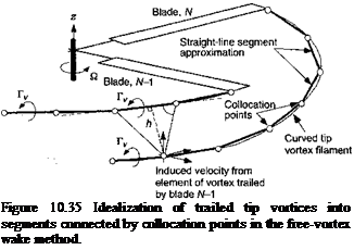
In the first instance, consider the rolled up tip vortices generated by each blade. For a rotor with Nb blades there will be an equal number of intertwining tip vortices (see Fig. 10.35). Generally, the filaments will have unequal circulation strengths along their length, which can be related to the lift (circulation) on the blade at the time of their formation. This means that both trailed and shed elements must be included in the solution to satisfy conservation of circulation. However, because this increases dramatically the number of free elements and the numerical costs, a tip vortex of average strength related to the rotor thrust (blade loading) is often assumed (see Section 3.3.8). A series of collocation points can be specified on the trailed vortex filaments, and these points are numerically convected through the flow field at the local velocity in accordance with the transport equation defined previously in Eq. 10.53.

Подпись: Figure 10.35 Idealization of trailed tip vortices into segments connected by collocation points in the free-vortex wake method.

General Solution Methodologies

Free-vortex wake models can be divided into two general types of solution method­ologies: 1. Time-stepping or time-marching methods, and 2. Relaxation or iterative meth­ods – see Leishman et al. (2002b). In the time-stepping method, the solution can be developed by an impulsive start of the rotor with no initial wake. The boundary condition specifies that each trailed vortex filament be attached to the blade at its point of origin, = 0. Alternatively, a prescribed wake geometry can be specified as an initial condition. In either case, the solution is stepped in the ^ (azimuthal) direction using a time integration scheme, and for a steady-state flight condition, a converged solution is obtained when the transients introduced by the initial condition die out and a periodic solution is achieved. The relaxation method, in contrast, specifies that the trailed vortex elements be attached to the blades as an initial condition, whereas periodicity is enforced as the boundary condition. The solution is stepped in the direction in an iterative manner, and convergence is obtained once the wake vortex geometry no longer distorts between successive iterations. Relaxation schemes have the advantage that they are numerically more efficient because periodicity of the wake solution can be imposed as a boundary condition. Also, relaxation schemes are generally free of the numerical instabilities that are often produced in some time-marching schemes as a consequence of round-off errors.

Free - Vortex Wake Analyses Подпись: (10.87)

Different numerical schemes can also be used within both the time-stepping and relax­ation approaches (i. e., explicit, implicit, or hybrid). Several rotor wake analyses use explicit type methods, which are simple in concept, but are particularly prone to various numerical problems associated with round-off errors. Consider, as an example, a representative PDE describing the convection of the vortex filaments such as

Spatial discretization would result in reducing this partial differential equation into a system of simultaneous ODEs that can be written as

Подпись: (10.88)dr

— = Ar + ПГ).

where A is the space discretization matrix. An explicit method for this equation would use a finite-difference scheme such as

(10.89)

Notice that the updated value of r at time n + 1 is based on values from the previous time step alone. Although this is one of the simplest methods, the truncation error in the solution for r is of order (At)2 per time step, and so the error can grow rapidly if the time step is too large. The high computational costs of most blade element based rotor analyses often require relatively large time (blade azimuth or Афь) steps with the wake solution, making the assessment of truncation errors an important consideration..

Implicit methods, in contrast, are free from many of these numerical problems. An implicit difference scheme to solve the example equation in Eq. 10.87 is

rn+ _ rn-+ At [Arn+І + v(r«+i)j _ (10.90)

In this case, the right-hand side also requires the evaluation of terms at the (n – j – l)th step, information that has not yet been determined. If the velocity term, V, is a simple function of r, then the equation can be easily simplified and solved as a set of simultaneous equations. For more complex velocity functions, however, V must first be linearized using a Taylor expansion, resulting in a semi-implicit scheme. This approach was applied to the FVM by Miller & Bliss (1993). While numerical errors are much smaller with this intensive computer-processing technique, it is not routinely used because it requires the simultaneous solution of a large set of linear equations at each time step.

A multistep or predictor-corrector method may also be used to solve the wake equations. In this approach, an explicit method is used to generate an approximate value for the current step

rn+l = rn + At [Arn + V(rn)], (10.91)

and this approximate, or predicted value, r, is then used to generate the final approximation to r"+1 using a corrector step such as

rn+l = rn + At [Arn+i + V'(rn+1)] . (10.92)

Predictor-corrector methods have a truncation error per step of order (At)3 and exhibit considerably better stability characteristics than explicit methods alone – see Crouse & Leishman (1993). They also require much less computation than implicit or semi-implicit schemes. However, this scheme requires two velocity field calculations per time step com­pared to one for an explicit method (see Question 10.8).

Bagai & Leishman (1995a, b; 1996) have further developed a FVM for rotor wake modeling based on a predictor-corrector scheme in a relaxation formulation, but with two modifications. First, the explicit predictor step is modified into the pseudo-implicit equation

~n+i =rn + At [дрп-и + . (10.93)

Подпись: = rn + At Подпись: Arn+U+ - (V(rn+l) + V(r")) Подпись: (10.94)

While the forcing (velocity) function is calculated explicitly from the previous time step, the position vectors at the current time-step also appear on the right-hand side (P+1). The above predictor equation, therefore, is no longer fully explicit. Second, the corrector step incorporates an averaging scheme whereby an average of the velocity function from the previous time step and the predicted value are used to update the corrected position vectors. This helps to improve the stability characteristics of the scheme. Once again, the position vectors at the current time step also appear on the right-hand side, also making the corrector step a pseudo-implicit equation, that is

Beddoes’s Generalized Wake Model

Another parsimonious but very effective prescribed wake model has been devel­oped by Beddoes (1985). In this model, it is also recognized that axial (vertical) trajectories of the tip vortices can be estimated if an assumption for the inflow distribution across the disk is made. Beddoes suggests the model

D = A.0 (l + Ex’ – E (y)3 l) , (Ю.81)

where x’ — x/R and у’ = y/R, deducing this form of the inflow from the measurements of Heyson & Katzolf (1957). Again, the evaluation of A., is based on momentum considerations. Beddoes suggests that E = x, where x is the wake skew angle, although this is generally too large and E = x /2 has been found to give better agreement with experimental results and with the FVM.

Although with these assumptions the solution for the wake can be obtained by solving directly Eq. 10.53, this still involves significant expense because of the repeated evaluation of the Biot-Savart law. Instead, Beddoes (1985) specifies the equations describing the wake. At the rear of the disk, in the region occupied by the wake,

V = 2Л.0 (l – E (y[/f |) , (10.82)

so that the vertical displacement of the tip vortex is given by

zip = – B’lfw + / bdfb, (10.83)

Jo

where z’ = z/R. Now, if л:’ір < — cos(t/q> — ^w) then the element on the vortex filament has not convected beyond the rotor disk and

Ґ" kdfb = – V) (l + E(cos(fb – + 0.5!Xtyw – I0>t’,p)3|)) *»• (10-84>

Подпись: = -2x„ (і - яі(у;ір)3і)) *, Подпись: (10.85)
Beddoes’s Generalized Wake Model

If cos(V^ — fw) > 0 then the vortex element has always been downstream of the rotor disk and in this case

If neither of the preceding conditions are met, then the element has spent part of the time within the disk and the remainder downstream of the disk and for this condition

Подпись:Подпись:Beddoes’s Generalized Wake Model(10.86)

РЛС / ( О P (Лп Kocic nf fll ас Д o/~l lirjfi /л n г tb л rvf

wu CK^pp/ ywu/v). UU HRS Odolo v)l ulCoC СЦиаииію, ui^ lihv^ wumpuu^iao ui

the tip vortex location with respect to the rotor can be calculated.

Beddoes’s Generalized Wake Model

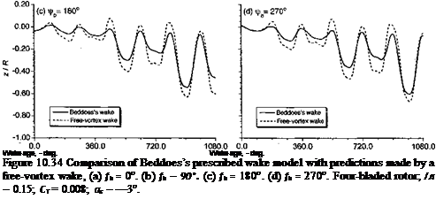
Figure 10.34 shows a comparison of the vertical components of the tip vortices in forward flight at д = 0.15 as obtained from the Beddoes prescribed-wake model and also from a FVM. Because the differences between the prescribed wake and the free-vortex wake are now much smaller compared to the rigid wake, for clarity the results in Fig. 10.34 are plotted in terms of vertical displacement versus wake age relative to the blade of origination. The agreement is good, and bearing in mind the relative simplicity of the prescribed-wake solution compared to the free-vortex wake (at least two orders of magnitude less expensive to compute), it is certainly a modeling option to consider in any form of rotor analysis. After the wake geometry is known, the induced velocity field can be computed through the application of the Biot-Savart law to the discretized vortex filaments. Because this incurs the highest cost of any vortex wake model, Beddoes (1985) suggests an alternative and

highly simplified approach of approximating the induced velocities from some elements of the wake by using elongated straight line segments, which retains the simplicity and low cost of semi-analytic models such as when using vortex rings.

Beddoes’s prescribed wake model seems to have received good attention from rotor analysts, and has been used in a number of aerodynamics and acoustic studies, mainly because of its excellent computational efficiency. Van der Wall (2000a) has performed an evaluation of the Beddoes wake model against measured airloads, wake displacements and В VI locations over the rotor disk in forward flight and has also suggested further improvements to the model – see van der Wall (2000b). While the predicted results seem good, it must be remembered that the tip vortex trajectories are still being prescribed a priori based on some generalized assumptions and not calculated based on the actual induced flow velocities near the rotor. Therefore, in the strictest sense, the prescribed wake model must be viewed as a postdictive model and must be validated for each and every rotor configuration, which is a formidable undertaking. The main problem, however, is this type of wake model does not offer the analyst much flexibility in terms of rotor design, despite the modest computational cost. This sought-after flexibility is obtained only with the next level in wake modeling, which is called the free-vortex wake method (FVM).

Modifications to Rigid Vortex Wake Models

Any number of assumptions about the induced velocity field near the rotor can be made to specify the right-hand side of Eq. 10.53 and decouple the equations. Other types of prescribed wake models for use in forward flight have also been derived on the basis of experimental observations. The advantage of these models is that, for some small additional computational effort, much better estimates of the rotor wake geometry can be obtained compared to a rigid wake. It has been observed from flow visualization experi­ments that the longitudinal and lateral distortions of the wake are relatively small compared to the vertical distortions. This means that the self-induced velocities in a plane parallel to the rotor plane are small: so for all the prescribed wake models it is still justified to use the undistorted tip vortex equations given previously by Eqs. 10.75 and 10.76. The differ­ences in the various prescribed wake models lie in the prescription of the vertical (axial) displacements of the tip vortices. Generally, these are defined using Eq. 10.77 as a basis, but with empirical or semi-empirical weighting functions being used to produce the wake distortions.

UTRC Generalized Wake Model

One such prescribed wake approach, used by Egolf & Landgrebe (1983), is called the Generalized Wake Model. The vertical displacements of the tip vortices are written as

Modifications to Rigid Vortex Wake Models(10.80)

Подпись:right-hand side of the preceding equation is simply a modification to the undistorted rigid wake; the E term is called an envelope function and is effectively an amplitude term, and

Modifications to Rigid Vortex Wake Models

Modifications to Rigid Vortex Wake Models

Figure 10.33 Representative rigid wake geometry in forward flight compared to free – vortex wake method and measurements, (a) Plan (top) view, (b) Side view, looking from retreating side. Four-bladed rotor; Cj = 0.008; fx — 0.15; a, = —3°. (Notice: Results for a four-bladed rotor have been computed, with the results for one blade being shown for clarity.)

the G term is a shape or geometric function. The vertical displacement envelope function is defined by

_ I fw exp(Ai for < 4л-,

I Mj/W + В for fw > 4n,

where the coefficients Ao, A, M, and В are functions of the number of blades, the ad­vance ratio, and the rotor thrust for a given rotor. The corresponding shape function
is given by the equations

N

E<« ‘nc cos n(fw – }fb) + g’ns sin n{fw – fh)} for 0 < < 2ж,

Подпись: G =n= 0 N

Dc cos n(J/w – fh) + sin п(^ш – Vt?)} for tAu, > 2n,

n—0

where the coefficients g^c, g^s, g"c, and are functions of the number of blades and advance ratio for a given rotor. Usually N takes a value of 12.

Like the hover prescribed wake models, the coefficients of the forward flight model have been deduced from experimental studies of the wake geometry. However, because forward flight experiments are much more difficult and time consuming to undertake, there are less data available. Nevertheless, as shown by Egolf & Landgrebe (1983), the agreement of this prescribed wake model with measured wake geometries has been found to be good. As a consequence, there is usually a significant improvement in the prediction of blade airloads compared to those obtained using an undistorted rigid wake.