Category Propellor Aerodynamics

The Curtiss Electric Propeller

The Curtiss Electric Propeller was very popular during WW II, and was used on many American single-engine fighters and light twin-engine bombers.

The Curtiss prop’s CSU worked on a different principle to the CSU’s mentioned above, using an electric motor to turn the blades either way. The reversible electric motor is driven by power from the aircraft’s battery and AC electrical system. The operation of the governor opens and closes circuits to drive the constant-speed unit in the required direction. Through a system of gears connecting the electric motor to the blades, the blade angle is changed. A brake holds the blade angle constant and then releases its hold whenever the electric motor is activated. The fine and coarse pitch limit stops are also electrically operated, with the addition of a mechanical fine/flat pitch limit stop to prevent reverse pitch being inadvertently selected.

The Curtiss Electric Propeller

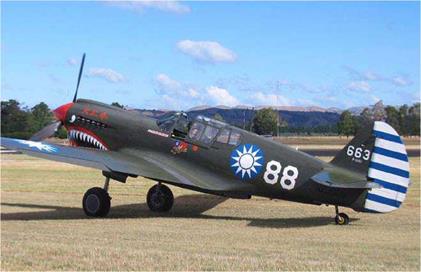
The Curtiss P-40 was equipped with an Allison V-1710 engine powering a Curtiss Electric, three-blade prop.

It is interesting to note, the Lockheed YC-130 Hercules transport prototype and the first ten production aircraft were fitted with Curtiss-Wright, three-blade electric propellers. Powered by the Allison T56 turboprop engine, the props rotated at a constant 1108 RPM; the thrust was varied by adjusting the prop’s blade angle. However, a problem with the electrically operated governor caused the CSU to overspeed or ‘hunt’ in either direction. This resulted in uneven thrust being produced and caused the aircraft’s nose to yaw from side to side. Overheating of the gearbox required frequent engine shut-downs. The problem with the Curtiss-Wright props was eventually corrected but not before a change was made to hydraulic CSU’s made by Aero Products, Allison’s subsidiary company. Subsequent Hercules models from the C-130B onwards were equipped with Hamilton Standard three, and later four-blade propellers. However, to follow the trend of modern turboprops aircraft, the new C-130J models have a
new type of free-shaft turboprop engine – a Rolls Royce AE 2100 of 4637 SHP driving six-blade composite props.

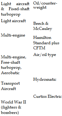
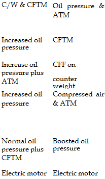
The following table briefly lists the different constant – speed unit types and their method of operation under normal forward thrust conditions:

Подпись: Light aircraft & Fixed-shaft turboprop Oil/counter- weight Light aircraft Beech & McCauley Multi-engine Hamilton Standard plus CFTM Multi-engine, Free-shaft turboprop, Aerobatic Air/oil type Transport Aircraft Hydromatic World War II (fighters & bombers) Curtiss Electric Подпись: C/W & CFTM Oil pressure & ATM Increased oil CFTM pressure Increase oil CFF on pressure plus ATM counter weight Increased oil pressure Compressed air & ATM Normal oil Boosted oil pressure plus CFTM pressure Electric motor Electric motor

Aircraft Class Type Fine/flat pitch Coarse Pitch

Abbreviations used in the above list:

C/W = Counterweights

ATM = Aerodynamic turning (or twisting) moment CFTM = Centrifugal turning moment.

The Hydromatic CSU

The constant-speed units mentioned above are all of the single-action type. The oil pressure acts on only one side of the piston with the opposing force provided by counterweights,

The Hydromatic CSU

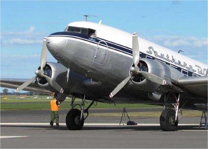
The Douglas DC-3 uses Hydromatic double­acting and feathering propellers.

compressed air and aerodynamic or centrifugal turning moments. In some units, a spring may also be used to assist the centrifugal turning moment.

For transport aircraft, Hamilton Standard introduced the Hydromatic double-action CSU, where oil pressure is directed to either side of the CSU as required. Normal engine oil pressure is fed to the upper side, or front of the piston to turn the blades to fine/flat pitch, assisted by the centrifugal turning moment. Engine oil pressure boosted to 450 PSI by the governor boost pump is directed to the lower side or back of the piston to turn the blades to coarse pitch. An increase of oil flowing to either side of the piston changes the prop blade angle via the cam connected to the piston. The advantage of having a double-action CSU is the need and weight of the spring and counterweight are excluded.

The Beech & McCauley Types

The Beech and McCauley types of CSU operate in a similar manner to the units described above. However, with these types of units there are no heavy counterweights attached to the blades. The prop blades are turned towards fine/flat pitch by the centrifugal turning moment and towards coarse pitch by oil pressure acting on the moveable piston.

The Hamilton Standard Type

The Hamilton Standard CSU operates on the oil/counterweight principle. The major difference is the direction of movement of the blades due to oil pressure acting on the piston in the cylinder. The increased pressure moves the cylinder forward over the stationary piston The cylinder is connected to the blades by a system of cams and gears. An increase of oil pressure turns the blades to fine/flat pitch assisted by the centrifugal turning moment acting on the blades. The opposing force is supplied by the centrifugal force acting on the heavy weights attached to the blade hub and the aerodynamic turning moment acting on, and turning the blades towards coarse pitch. Note the oil pressure acting on the piston turns the blades in the opposite direction to that described for the Beech and McCauley CSU’s.

Air/Oil Type

The air/oil CSU works in the same manner as the Hamilton Standard CSU with the addition of compressed air pressure to assist turning the blades towards coarse pitch. The compressed air chamber is filled with dry air or nitrogen gas at a pressure of approximately 175 PSI. The reason for using dry air is to prevent corrosion and freezing of the moisture within the system. Compressed air is used on newer types of CSU in place of counterweights in order to save weight.

The Oil/Counterweight Type

One of the most common type of constant-speed unit is the oil/counterweight type, which consists of an engine driven centrifugal governor with an oil valve and spring loaded counterweight. Oil pressure is supplied to the hydraulically operated piston by a governor driven oil pump which boosts the engine lubricating oil pressure from about 60 PSI to 275 PSI. The desired RPM is selected with the propeller pitch control, which in turn, controls the flow of oil to or from the piston via the governor operated oil valve. Oil pressure then moves the piston in the stationary cylinder to turn the blades

The Oil/Counterweight Type

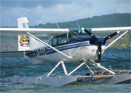
This Cessna 206 Stationair floatplane is powered by a three-blade McCauley propeller.

to coarse pitch, assisted to a lesser degree by the aerodynamic turning moment of the propeller blades. The opposing force produced by the counterweights will turn the blades towards fine/flat pitch assisted by the centrifugal turning moment of the blades. The aerodynamic and centrifugal turning moments were covered earlier in ‘Prop Stress’.

Constant-speed Units

The Constant-speed Unit

The constant-speed unit (CSU) located at the propeller hub is a speed-sensitive device used to select or maintain a constant engine RPM within the CSU’s operating range of approximately 1600-2800 RPM. The unit is one of a variety of types in general use powered either electrically, or more commonly by hydraulics. The advantage of using a constant-speed propeller over a fixed-pitch prop is increased take-off and climb performance due to maximum engine RPM producing greater brake horsepower, a lowering of fuel consumption and less wear on the engine. Power, air speed and air density are three variables affecting the propeller, which are compensated for by the constant-speed unit.

Constant-speed Units

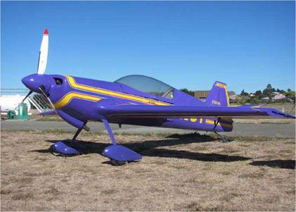
An AkroTech Giles G202 unlimited-level, aerobatic aircraft.

Basically, a constant-speed unit makes use of fixed and variable forces to change the blade angle. The CSU’s governor supplies the variable force and the fixed force is either from internal compressed air pressure, or from the aerodynamic forces acting on the prop blades and centrifugal forces acting on the counterweights to oppose the governor. Which way the governor or the forces act depends on the design of the CSU and to some extent on the prop’s condition of operation, either under power or windmilling.

The CSU governor is connected to the engine’s crankshaft by gearing and so will detect any change in the engine’s RPM. Any increase in RPM above the preset value will cause the governor to turn the blades to a coarser pitch. This will place a greater torque load on the engine causing a decrease in RPM to the preset value. The opposite happens with a reduction in RPM; the governor produces a lower blade pitch angle reducing torque and allowing the engine revs to pick up again. The hydraulic CSU makes use of the engine’s lubricating oil acting on a piston to adjust the blade angle. Normal engine oil pressure maybe used, but on some units the oil pressure is boosted by a pump attached to the governor. Increased oil pressure has greater power to adjust the blade angle more quickly. Feathering props usually incorporate an auxiliary oil system to feather the blades because normal engine oil pressure maybe insufficient following an engine failure. The linear movement of the piston is transmitted by linkages, cams and/or gears to rotate the prop blades to the required angle.

The constant-speed unit found on single-engine light aircraft and fixed-shaft turboprops use oil pressure to turn the blades to coarse pitch. These are the oil counterweight type made by Beech and McCauley and are less complex, cheaper and lighter in weight than the type used on light piston-twin aircraft. For twin-engine aircraft and free-shaft turboprops, the CSU works in the opposite sense, with oil pressure turning the blades to fine/flat pitch, favouring the air/oil and Hamilton Standard

Hydromatic CSU’s. The advantage of this type is when an engine fails; a loss of oil pressure will start the blades moving through coarse pitch into the feathered position.

Purpose-built aerobatic aircraft employ a CSU similar to those mounted on twin-engine aircraft, where the oil pressure turns the blades towards fine/flat pitch. The continuously varying attitudes achieved by aerobatic aircraft can momentarily decrease the lubrication oil from reaching the CSU. If the CSU worked on the principle where the oil pressure increases the blade angle, this could result in a prop over-speed depriving the engine of its vital oil supply; this is also a very good reason to avoid extreme attitudes in non-aerobatic aircraft. Using the CSU type where the oil pressure turns the prop blades to fine/flat pitch ensures the prop reaches its fine/flat pitch-stop before the engine can over-speed or be starved of lube oil.

Constant-speed Units

The Yak aerobatic aircraft fleet use centrifugal weights attached to the propeller to assist prop pitch change. This is a YAK 55m model.

The following is a brief look at some of the CSU’s principle of operation, pilot handling and the faults that may occur in the unit.

Propfans

The Propfan is a turbine engine driving a tractor or pusher, single or contra-rotating, multi-bladed propeller of advance

Propfans

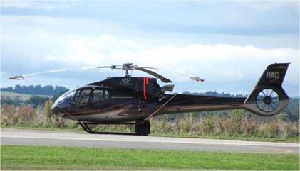
The Eurocopter EC 130 with a tail rotor Fenestron, which reduces tail rotor noise by 50% due to its unevenly spaced blades.

design. It was intended to be the power plant of the future for short to medium haul air transport aircraft. Turboprop aircraft are ideal for short haul feeder routes cruising at around 350 knots at altitudes up to 25,000 feet, while the jet transports cruise higher at 450-550 knots. The Propfan is designed to combine turboprop economy with jet transport performance. The Propfan’s major disadvantage is the fan blade’s high tip speed associated with the relatively high cruise speed of the aircraft. The high tip speed suffers from separation of the air flow boundary layer over the blades causing noise and a loss in efficiency due to compressibility problems. More of this later.

From the foregoing, it is obvious the Propfan is not an ordinary propeller, but an advanced turboprop designed to meet a specific need in the air transport industry. The Propfan is used on aircraft, which are designed to cruise at a much higher speed than conventional prop driven aircraft, and must be designed accordingly. The main difference between Propfan and propeller aircraft is the number and shape of the individual blades. The relatively straight shape of normal prop blades is totally unsuitable for the high operating transonic speeds of the Propfan. Therefore, the Propfan’s blades are swept back scimitar shape, with the sweepback being far more prominent than a turboprop’s scimitar shaped blades. This shape is essential to maintain efficiency at high transonic speeds for the same reason a jet aircraft’s wings are swept back. The blades are designed as high-speed airfoils with a thin lenticular section and high aspect ratio planform, producing a high lift/drag ratio. A very high helix angle is also used, which combined with its high advance per rev produces in effect, a relatively slow air flow over the blades. Ironically, although transonic speeds require a prop with scimitar shaped blades, a straight blade is required for a fully supersonic propeller, due to aeroelasticity problems of stress and flutter where a straight prop blade is superior to a scimitar blade.

Propfans

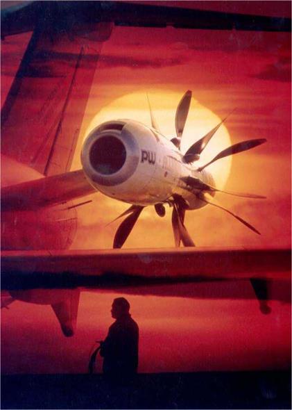
A dramatic double-exposure of the McDonnell Douglas MD – 80 test-bed with the P&W Allison Model 578-DX Propfan, at sunset. Photo courtesy Hamilton Standard, Connecticut, USA.

Propfan blades are made from titanium or composite materials to provide greater strength, lightweight and stiffness. It is much easier to attach a great number of lightweight composite blades to a prop hub than heavier metal blades. Six – blade composite props are becoming more common on new generation turboprop transport aircraft, with up to twelve blades being used on a contra-prop allowing smaller diameter props. The Propfan blades appear to be short and stubby due to the hub/radius ratio of 0.45, double that of a conventional propeller. This provides the advantage of lower tip speeds of around 750-800 feet per minute, although some Propfans may have tip speeds operating in the transonic range of Mach 0.8 to 1.2, if the designer requires this. Although it maybe acceptable for a Propfan’s blade tip to operate in this range, the rest of the blade is usually operating at the more conventional subsonic speeds. On a conventional prop, smaller blades have a reduced diameter with increased prop disc loading, leading to a loss in efficiency. Adding a greater number of blades, as found on a contra-Propfan for example, reduces the prop blade loading thereby regaining the lost efficiency. The multi-bladed Propfan handles the undesirable problem of compressibility better than a conventional prop. The air flow through the Propfan cascades over the numerous blades allowing compressibility to build up gradually with a minimum loss of energy. Depending on the Propfan’s design, the prop disc loading (as opposed to prop blade loading) may be similar or up to twice that of a conventional propeller

The number of blades, small diameter, scimitar shape and high aspect ratio, all leads to an increase in propulsive efficiency 20% better than a conventional high by-pass turbofan at Mach 0.8. At cruising speeds between Mach 0.7 and 0.85, the propulsive efficiency is about 72-80% for a single-rotation Propfan and 85-90% for a contra-Propfan. This puts the Propfan’s efficiency as being better than both a conventional prop and turbofan at the Propfan’s design cruise speed of around 450 knots.

Fuel burn will be down 25-45% less than a conventional jet engine, which was the original reason for developing the Propfan due to the fuel crises of the mid 1970s. The fuel burn figures and propulsive efficiency for a contra-Propfan are better than those for a single rotation Propfan. The wake turbulence between the two fans of a contra-Propfan increases noise by 2-3 dB, although the aft fan will recoup some of the lost power in the wake from the front fan. Installing a duct or shroud around the Propfan will attenuate the noise, which being higher than a conventional prop is a distinct disadvantage for a civil transport aircraft. With a duct or shroud installed, the Propfan then becomes known as a Ducted Fan. In the rare event of the prop throwing a blade, it could be contained within the shroud, a distinct advantage especially on an airship!

For all its advantages, the Propfan research ended in the USA, however it continued slowly in Russia with production models now flying.

Propulsors

Propulsors have been around for many years now, their origin dating back to 1910. The propulsor is a propeller of short radius mounted inside a duct or shroud, hence its alternate name of Ducted Fan or Shrouded Prop. It is ideally suite to special purpose-built light aircraft or airships, which are designed to fly missions at around 80 knots or slower.

Due to resonance effects, Propulsors always have an odd number of blades, usually around five-blades per prop. The prop blade radius is relatively small around 0.72 times the size of a conventional propeller, but the propulsive efficiency is as good as or better than a normal propeller of greater diameter. The advantage of the smaller diameter of the Propulsor’s blades allows it to operate to higher RPM without propeller reduction gear, before the tip speed suffers from compressibility problems. It will produce a similar amount of static prop thrust per horsepower as a prop 1.3 times larger due to the presence of the shroud. The shroud’s air intake section is bell shaped, or to be precise, it is an annular airfoil. The shroud is designed specifically to help smooth the airflow through the prop disc. The air’s inflow velocity into the shroud increases, resulting in a drop in air pressure in front of the prop. The air flow then exits the duct with the air flow stream tube the same diameter as the duct exit, as opposed to the vena contracta of a conventional prop. Prop tip vortices will be greatly reduced due to the close tolerance between the prop tips and the shroud. Because the propeller radius is shorter than a conventional propeller, it follows the blade tip speed will be lower resulting in less prop noise and freedom from compressibility problems In the rare event of the prop

Propulsors

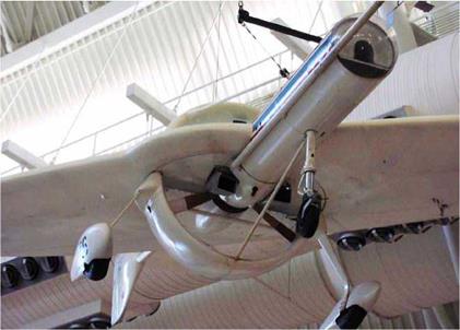
An Unmanned Aerial Vehicle (Drone) powered by a Ducted Fan. This UAV resides in the Udvar-Hazy Centre, Chantilly, Va.

throwing a blade, it could be contained within the shroud, a distinct advantage especially on an airship!

Although the Propulsor has some advantages over the conventional prop, it does have some disadvantages too. The shroud will absorb some of the noise making it quieter to observers at the side of the aircraft (it is ideal for airships). However, this advantage is offset by the fact the noise will be focused fore and aft, making it noisier in those areas, which is where the cabin is located on single-engine Propulsor aircraft. The shorter radius of the prop could imply a saving in weight, but this may be offset by the weight of the extra blades (usually five or more). In addition, the weight of the shroud must also be taken into account, plus its extra cost and drag penalty. For all the Propulsor’s advantages and disadvantages, only a small increase in efficiency is realized, and that is mostly at the low end of the speed range.

Some helicopters have a Ducted Fan tail rotor known as a Fenestron, a type of Propulsor. The French Aerospatiale’s Gazelle (1967) and Dauphin (1972) helicopters both have a thirteen blade, composite Fenestron mounted in a duct within the tail boom for improved performance, replacing the conventional tail rotor. The later 1989 model Dauphin’s fenestron has only eleven blades to further improve its performance

To conclude, the propulsor powered aircraft has its propulsive efficiency suited to the lower end of the speed range. At the high end of the speed range, the propulsive efficiency of the Propfan is suited to the medium range airliner, designed to cruise at speeds closer to those of the jet-powered aircraft with turboprop efficiency.

Turboprops, Propulsors & Propfans

Turboprops

Turboprops are of two different types, the free-turbine and the fixed-shaft. The fixed-shaft is also known as single-shaft or direct-drive. This type of engine has its compressor/turbine mounted on the same shaft as the propeller. The other type of turbine is the free-turbine where the compressor/turbine is mounted on its own shaft separate from the prop shaft. It supplies a flow of exhaust gas pressure to the power turbine attached to the prop shaft. There is no direct mechanical link between the power turbine and the gas generator, hence the name of free-turbine. A very good example of this type of engine is the well-known Pratt & Whitney PT6A, which in its various versions powers three quarters of the light turbine fleet in the Western world.

The turboprop engine, whether it is fixed-shaft or free – turbine, works on the same principle as the jet engine, where

Turboprops, Propulsors & Propfans

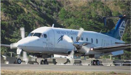
The Beech 1900D commuter airliner has two PT6A-67 free – shaft turboprop engines rated at 1279 SHP each.

most of its heat energy is converted to shaft horsepower by the turbine. As opposed to the turbojet or turbofan which ejects a small volume of air rearwards at high velocity to generate thrust, the turboprop imparts a low velocity to a large mass of air via the propeller. The turboprop therefore, has higher propulsive efficiency than the turbojet at relatively lower air speeds, especially on take-off. The exhaust on some turboprops also ejects a small amount of jet thrust and when this is added to the shaft horsepower (SHP) available from the propeller, it is then termed equivalent shaft horsepower (ESHP). The prop thrust produced with the engine idling whilst taxiing can be more than sufficient and to warrant the use of frequent brake application or beta mode. To alleviate this problem, the constant speed unit may have a ground fine/ flat pitch stop to reduce the blade’s angle of attack to a value less than that of the normal fine/flat pitch stop setting, thereby reducing thrust.

Turboprops, Propulsors & Propfans

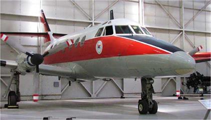
The Scottish Aviation Jetstream 1 is powered by twin Turbomeca Astazou fixed-shaft turboprop engines. This aircraft is located in the RAF Museum Cosford, England.

The two different types of turboprop engines require a slightly different approach in handling on the part of the pilot. The free-shaft turboprop is operated in a similar way to the piston-engine where the thrust lever (throttle) controls the compressor speed of the gas generator, while the prop RPM and hence the power absorption, is controlled by the propeller pitch lever. Propeller RPM (N1) and compressor speed (N2) are therefore both controlled independently of each other Because the compressor turns at a very high speed of around 15,000 RPM or more, a reduction gear is installed to drive the prop at a more sedate speed of 1000-2000 RPM. With the propeller and power turbine separated from the compressor, propeller inertia does not retard the very high acceleration possible with the free-turbine. Although the free-shaft engine has three engine controls, (the third is the condition lever or fuel control) compared to only two controls for the fixed-shaft engine, the free-shaft is a much easier engine for the pilot to operate

Power output on the fixed-shaft engine is controlled by either adjusting the fuel flow or by varying the compressor RPM and power absorption via the propeller pitch and thus the airflow through the engine. Fuel flow control and the constant-speed unit’s selection of blade angle to maintain RPM are interlocked to avoid compressor surge or over temping the engine. A low RPM and high fuel flow will cause an over rich fuel/air ratio, virtually flooding the engine. The engine operates at a very high RPM throughout all flight regimes and due to the narrow RPM range between flight-idle and maximum RPM, a high increase in power will require a rapid change in the blade angle. An engine failure on a fixed-shaft turboprop is far more serious than it is for a free-turbine. This is especially so during the approach when the prop blade is at a low angle of attack (fine/flat pitch) because the prop will absorb the large power required by the compressor. An auto-feathering device is required to turn the blades to the feathered position at as high a rate as possible.

The Balanced Prop

The propeller must be in static and dynamic balance to reduce stress caused by vibrations and make for a smooth running propeller. Generally, a three-blade propeller runs more

The Balanced Prop

This Messerschmitt Bf 109e received prop damage in the crash­landing after being shot down in England, in 1940. This aircraft is on display in the Imperial war Museum, Duxford, UK.

smoothly than a two-blade prop; no matter how many blades there are it is important the propeller is in perfect balance.

If a two-blade prop has a 100-gram weight placed at the tip of one blade and 200-gram weight placed half way along the other blade, the prop would be in a state of static balance. A prop that is statically stable would not rotate on its prop shaft (if it were free to do so) from any position. The prop is then said to be in a state of static balance but it would not be dynamically balanced and would vibrate severely at high RPM. To be in dynamic balance, the prop has to be balanced evenly for the same reason a car tyre is balanced to prevent it from vibrating at high speed on the road.

There are at least two methods to balance the prop. One, the prop can be removed from the aircraft and placed on a workshop stand for balancing. This is a relatively simple method but not as accurate as using an electronic balancer, such as a Chadwick-Helmuth Vibrex Dynamic balancer. A small accelerometer is placed on top of the engine, which measures vibrations in inches per second at different RPM. The electronic balancer indicates where, and how much weight is to be placed on the prop to balance it. Again, this is similar to balancing a car wheel. A correctly balanced propeller will have the vibrations reduced to around 0.04 inches per second. A smooth running prop makes the ride more enjoyable and less fatiguing for the plane’s occupants.

Prop Stress

Material stress can be divided into four main categories of torsional, tensile, compression, and bending stress. Any one stress or combinations of stress can be present acting on an aircraft or propeller at any one time. Stress is measured as a force per unit area. The stress will vary depending on the operating conditions of the propeller, the stress force can be reversed if the propeller is windmilling or with reverse thrust application. Life for a propeller is not an easy one!

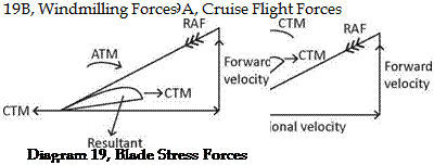
Reference to Diagram 19, Blade Stress Forces, shows the centrifugal force caused by the spinning propeller acting from the propeller hub through the leading and trailing edges of the propeller blade. The centrifugal force is divided into two components, one causing tension (tensile stress) due
to stretching and the other component causing a centrifugal turning moment (torsional stress).
Prop Stress
The tensile stress tends to flow through the propeller blades outwards, in effect stretching the blade in length and generating a considerable force on the propeller hub and increases towards the propeller tip .

The centrifugal turning moment (torsional stress) acting at 90 degrees to the propeller axis produces a turning moment around the propeller pitch change axis tending to turn the blades towards fine/flat pitch. This force is opposed by the pitch change mechanism, which is placed under stress, but is assisted to a certain degree by the aerodynamic turning
moment during normal cruise conditions, which tend to turn the blades towards coarse pitch. The pitch change axis is normally to the rear of the blade’s centre of pressure. The resultant aerodynamic force acting at the centre of pressure will tend to turn the propeller blades in the opposite direction; the direction is reversed when the propeller is windmilling causing the resultant force to act rearwards. The aerodynamic turning moment is acting in the same direction as the centrifugal turning moment and turns the blades towards fine/flat pitch. The centrifugal turning moment is a more powerful force than the aerodynamic turning moment and causes the most stress. Torsional stress forces increase with the RPM squared.

Additional to the stress mentioned above, is the bending stress on the blades caused by the thrust (blade loading) of the propeller. The blade loading is measured in horsepower per square foot. The force generated by the propeller tends to bend the blades forward when under power, while the tension in the blade caused by the centrifugal force opposes the thrust, which tends to straighten the blades out. Bending stress will be reversed in direction with reverse thrust application on the landing rollout.

At normal cruise RPM, the stress on the prop blades will be approximately 4500 pounds per square inch. On some engine/ prop combinations, a destructive vibratory frequency could exist at around 1900-2200 RPM. This torsional vibration can increase stress on the prop tips to that double experienced at normal cruise RPM. This is due to varying aerodynamic loads acting on the prop caused by a high vibration frequency coupled with the high inherent vibrations of the engine cylinder firing pulsations. If the vibration from the propeller coincides with those caused by the engine, a severe vibration will result. This is a different vibration to that caused by an out of balance prop and the pilot is unlikely to notice it. When the propeller’s and engine’s vibration synchronizes the amplitude of vibration can rapidly increase causing severe stress with possible blade failure or hub damage with disastrous results. A caution arc on the engine tachometer covers the RPM range to be avoided for continuous operation. This problem is only peculiar to certain aircraft: those aircraft with composite props are less prone to this vibration, while turboprops are totally free due to their lack if cylinder vibration. The red line at the top end of the tachometer scale indicates the maximum RPM permissible and exceeding the redline limit, apart from engine operating limitations, would allow the prop tips to reach the speed of sound. Additional stress would then be caused due to vibration flutter caused by the high propeller tip speed. Although safety margins are built in, red line limits should never be exceeded intentionally at any time.

Another form of stress can be induced by stone or gravel ingestion through the prop disc, and striking the blade’s leading edge. This will cause damage in the form of knicks, or stress raisers, which can lead to stress concentrations. The blades flexing under normal loads, especially in the area from 12.5 cm to 23 cm (5 to 9 inches) from the tips can lead to metal fatigue and loss of the prop tip. The result will be extreme vibrations caused by the prop being out of balance and could lead to the engine being torn from its mounts. With the engine heading earthwards and the aircraft’s centre of gravity moved well aft, it would be very difficult to achieve a balanced glide, the end result can easily be imagined! If the engine is still onboard, but shaking badly, it is imperative the engine is shut down and the prop feathered if possible. If the propeller is not the feathering type, reduce air speed as low as possible until the engine stops. Prevention is the best cure; any knicks found on the prop should be filed, or dressed out to prevent a crack from forming. Avoid taxiing over loose gravel if possible, but if it is unavoidable reduce power to a low RPM. Never run­up an engine over loose gravel and when taking-off, open the throttle slowly to get the aircraft moving before going to full

Prop Stress

The 1917, WW I, Bristol Bulldog IIA has prop tipping on the prop’s leading edges. It is displayed in the RAF Hendon Museum, London.

power. This technique will allow the prop to blow the gravel well clear without causing any damage to the prop blades. Tail – wheel aircraft have a greater clearance between the prop tips and the ground and are therefore less prone to stone damage than their trike counterparts.

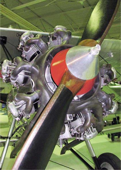
Sharp taxi turns can induce stress on the prop because the prop acts in the same way as a gyroscope due to its spinning mass and will attempt to resist any changes in direction. All power changes should be made smoothly and gently to avoid any undue stress being applied to the engine or the prop attachment bolts On a wooden prop, check the metal sheathing, (also known as prop tipping) on the leading edge of

Prop Stress

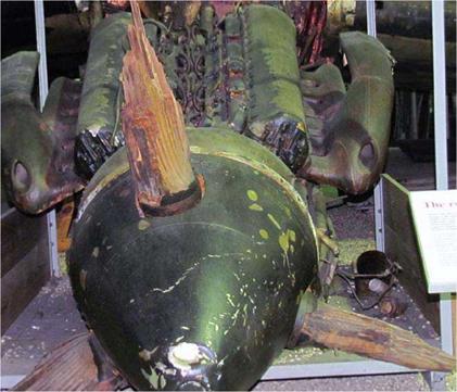
The wooden prop blades on this Handley-Page Halifax II bomber were sheared off during its war time crash-landing. The Halifax is displayed as recovered in the RAF Hendon Museum, London.

each blade is secure and free of any damage. Also, there should be no splits or cracks in the wood or separation between the wood laminations. A wood prop not used for long periods should be parked in the horizontal position to equalize the moisture content in each blade.

The ultimate stress force a prop can endure occurs when the prop blades strike the ground during a crash or wheels-up landing. Metal blades will bend either backwards or forwards during the impact. The resulting force, which in turn depends on a number of factors determine which way they bend. These factors include the blade chord, shape, and pitch, and the aircraft’s forward speed at the time of impact and also if the engine is providing power to the prop, or just idling. If the aircraft slide sideways the blades will buckle as well as bend. This kind of treatment is to be avoided to say the least! Wooden props and their engines can generally fare better in a crash landing. The wooden prop is more likely to break up than a metal prop and absorb some of the impact stress, protecting the engine somewhat. If you have the misfortune to forget to lower the undercarriage on the approach, you may hear the prop making ground contact as you flare for the landing. Do not attempt a go-around at this late stage in the hope of landing wheels-down on the next attempt. The damage is now done to the prop and the inherent forces associated with a full power climb could lead to total prop destruction and loss of the aircraft. It is safer to carry on with the landing and ride out the ensuing belly-ride. It must now be obvious the prop is a very important part of the aircraft and deserves to be treated gently with the utmost respect.